USER MANUAL JEPR Jandy
Jandy Pro Series JEP-R
Variable-Speed Pump Digital Controller
For use with Jandy Pro Series Variable-Speed Pumps
For Indoor or Outdoor Installations
WARNING
FOR YOUR SAFETY - This product must be installed and serviced by a contractor who is licensed and qualified in pool equipment by the jurisdiction in which the product will be installed where such state or local requirements exist. The maintainer must be a professional with sufficient experience in pool equipment installation and maintenance so that all of the instructions in this manual can be followed exactly. Before installing this product, read and follow all warning notices and instructions that accompany this product. Failure to follow warning notices and instructions may result in property damage, personal injury, or death. Improper installation and/or operation will void the warranty.

Improper installation and/or operation can create unwanted electrical hazard which can cause serious injury, property damage, or death.
ATTENTION INSTALLER - This manual contains important information about the installation, operation and safe use of this product. This information should be given to the owner/operator of this equipment.
Table of Contents
Section 1. IMPORTANT SAFETY INSTRUCTIONS .... 3
1.1 Safety Instructions ....3
1.2 Pool Pump Suction Entrapment Prevention Guidelines....6
Section 2. Installation of the Digital Controller .... 7
2.1 Introduction....7
2.2 The Controller Panel....7
2.3 The Controller Components....7
2.3.1 Additional materials....8
2.4 Installation of the Backplate onto an Electrical Box....8
2.5 Installation of the Backplate on a Flat Wall 8
2.6 Connection to Jandy ^ Pro Series variable-speed Pump....8
2.7 Variable Speed Pump Switch Settings .....9
2.8 Connection to Remote Contacts....9
2.9 Remote Operation 10
2.10 Remote Closure 4 Behavior....10
2.11 Remote Closure 4 Application
- Booster Pump Support ....10
Section 3. User Operation of the Variable-Speed Controller .... 11
3.1 The Controller Interface....11
3.2 Basic Functions ..... 11
3.3 OFF Mode....11
3.4 RUN Mode 11
3.5 Manual Start and Stop 12
3.6 Pump Speed Setting....12
3.7 Timeclock Setup and Operation....12
3.8 Keypad Lock....13
Section 4. Service Setup Options ...... 13
4.1 Entering Service Setup....13
4.2 Minimum and Maximum Pump Speeds....13
4.3 Load Defaults....14
4.4 Last Fault....14
4.5 Priming Speed and Duration....14
4.6 eStar Speed....15
4.7 Pump Freeze Protect Operation....15
4.8 Selecting Pump Type....15
4.9 Display Power Usage 15
Section 5. User Set Up Options....16
5.1 Setting Time-of-Day 16
5.2 Labeling Speeds....16
5.3 General Labels ......16
5.4 Custom Labels....16
5.5 Display Light Control....16
5.6 Language Selection....17
5.7 Run Duration (Speeds 3 and 4 Only)....17
5.8 Password Protect....17
DATE OF INSTALLATION
INSTALLER INFORMATION
INITIAL PRESSURE GAUGE READING (WITH CLEAN FILTER)
PUMP MODEL HORSEPOWER
FILTER MODEL _SERIAL_NUMBER
CONTROLLER MODEL SERIAL NUMBER
NOTES:
Section 1. IMPORTANT SAFETY INSTRUCTIONS READ AND FOLLOW ALL INSTRUCTIONS
1.1 Safety Instructions
All electrical work must be performed by a licensed electrician and conform to all national, state, and local codes. When installing and using this electrical equipment, basic safety precautions should always be followed, including the following:
| WARNING |
| RISK OF SUCTION ENTRAPMENT HAZARD, WHICH, IF NOT AVOIDED, CAN RESULT IN SERIOUS INJURY OR DEATH. Do not block pump suction, as this can cause severe injury or death. Do not use this pump for wading pools, shallow pools, or spas containing bottom drains, unless the pump is connected to at least two (2) functioning suction outlets. Drain covers must be certified to the latest published edition of ANSI®/ASME® A112.19.8 or its successor standard, ANSI/APSP-16. |
| WARNING |
| To reduce the risk of injury, do not permit children to use this product. |
| WARNING |
| To reduce the risk of property damage or injury, do not attempt to change the backwash (multiport, slide, or full flow) valve position with the pump running. |
| WARNING |
| To reduce the risk of injury, do not remove the suction fittings of your spa or hot tub. Never operate a spa or hot tub if the suction fittings are broken or missing. Never replace a suction fitting with one rated less than the flow rate marked on the equipment assembly. |
| WARNING |
| Prolonged immersion in hot water may induce hyperthermia. Hyperthermia occurs when the internal temperature of the body reaches a level several degrees above the normal body temperature of 98.6°F (37°C). The symptoms of hyperthermia include dizziness, fainting, drowsiness, lethargy, and an increase in the internal temperature of the body. The effects of hyperthermia include: 1) unawareness of impending danger; 2) failure to perceive heat; 3) failure to recognize the need to exit spa; 4) physical inability to exit spa; 5) fetal damage in pregnant women; 6) unconsciousness resulting in a danger of drowning. |
| WARNING |
| To Reduce the Risk of Injury -a) The water in a spa should never exceed 104°F (40°C). Water temperatures between 100°F (38°C) and 104°F (40°C) are considered safe for a healthy adult. Lower water temperatures are recommended for young children and when spa use exceeds 10 minutes.b) Since excessive water temperatures have a high potential for causing fetal damage during the early months of pregnancy, pregnant or possibly pregnant women should limit spa water temperatures to 100°F (38°C).c) Before entering a spa or hot tub, the user should measure the water temperature with an accurate thermometer since the tolerance of water temperature-regulating devices varies.d) The use of alcohol, drugs, or medication before or during spa or hot tub use may lead to unconsciousness with the possibility of drowning.e) Obese persons and persons with a history of heart disease, low or high blood pressure, circulatory system problems, or diabetes should consult a physician before using a spa.f) Persons using medication should consult a physician before using a spa or hot tub since some medication may induce drowsiness while other medication may affect heart rate, blood pressure, and circulation. |
WARNING
To minimize risk of severe injury or death, the filter and/or pump should not be subjected to the piping system pressurization test.
Local codes may require the pool piping system to be subjected to a pressure test. These requirements are generally not intended to apply to the pool equipment, such as filters or pumps.
Jandy pool equipment is pressure tested at the factory.
If, however, the WARNING cannot be followed and pressure testing of the piping system must include the filter and/or pump, BE SURE TO COMPLY WITH THE FOLLOWING SAFETY INSTRUCTIONS:
- Check all clamps, bolts, lids, lock rings, and system accessories to ensure they are properly installed and secured before testing.
- RELEASE ALL AIR in the system before testing.
• Water pressure for test must NOT EXCEED 35 PSI.
• Water temperature for test must NOT EXCEED 100°F (38°C).
- Limit test to 24 hours. After test, visually check system to be sure it is ready for operation.
Notice: These parameters apply to Jandy® Pro Series equipment only. For non-Jandy equipment, consult the equipment manufacturer.
WARNING
Due to the potential risk of fire, electric shock, or injuries to persons, Jandy Pumps must be installed in accordance with the National Electrical Code® (NEC®), all local electrical and safety codes, and the Occupational Safety and Health Act (OSHA). Copies of the NEC may be ordered from the National Fire Protection Association, 470 Atlantic Ave., Boston, MA 02210, or from your local government inspection agency.
WARNING
RISK OF ELECTRIC SHOCK, FIRE, PERSONAL INJURY, OR DEATH. Connect only to a branch circuit that is protected by a ground-fault circuit-interrupter (GFCI). Contact a qualified electrician if you cannot verify that the circuit is protected by a GFCI. Make sure such a GFCI should be provided by the installer and should be tested on a routine basis. To test the GFCI, push the test button. The GFCI should interrupt power. Push the reset button. Power should be restored. If the GFCI fails to operate in this manner, the GFCI is defective. If the GFCI interrupts power to the pump without the test button being pushed, a ground current is flowing, indicating the possibility of electrical shock. Do not use the device. Disconnect the device and have the problem corrected by a qualified service representative before using.
WARNING
Incorrectly installed equipment may fail, causing severe injury or property damage.
WARNING
- Do not connect system to an unregulated city water system or other external source of pressurized water producing pressures greater than 35 PSI.
- Trapped air in the system can cause the filter lid to be blown off, which can result in death, serious personal injury, or property damage. Be sure all air is out of the system before operating.
CAUTION
Do not start pump dry! Running the pump dry for any length of time will cause severe damage and will void the warranty.
WARNING
People with infectious diseases should not use a spa or hot tub.
To avoid injury, exercise care when entering or exiting the spa or hot tub.
Do not use drugs or alcohol before or during the use of a spa or hot tub to avoid unconsciousness and possible drowning.
Pregnant or possibly pregnant women should consult a physician before using a spa or hot tub.
Water temperature in excess of 100^ F ( 38^ C) may be injurious to your health.
Before entering a spa or hot tub measure the water temperature with an accurate thermometer.
Do not use a spa or hot tub immediately following strenuous exercise.
Prolonged immersion in a spa or hot tub may be injurious to your health.
Do not permit any electric appliance (such as a light, telephone, radio, or television) within five (5) feet (1.5m) of a spa or hot tub.
The use of alcohol, drugs or medication can greatly increase the risk of fatal hyperthermia in hot tubs and spas.
Water temperature in excess of 100^ F ( 38^ C) may be hazardous to your health.
WARNING
To avoid injury ensure that you use this control system to control only packaged pool/spa heaters which have built-in operating and high limit controls to limit water temperature for pool/spa applications. This device should not be relied upon as a safety limit control.

Attention installer: Install to provide drainage of compartment for electrical components.
SAVE THESE INSTRUCTIONS
1.2 Pool Pump Suction Entrapment Prevention Guidelines
WARNING
SUCTION HAZARD. Can cause serious injury or death. Do not use this pump for wading pools, shallow pools or spas containing bottom drains, unless the pump is connected to at least two (2) functioning suction outlets.
WARNING
Pump suction is hazardous and can trap and drown or disembowel bathers. Do not use or operate swimming pools, spa, or hot tubs if a suction outlet cover is missing, broken, or loose. The following guidelines provide information for pump installation that minimizes the risk of injury to users of pools, spas, and hot tubs:
- Entrapment Protection - The pump suction system must provide protection against the hazards of suction entrapment.
- Suction Outlet Covers - All suction outlets must have correctly installed, screw-fastened covers in place. All suction outlet (drain) assemblies and their covers must be properly maintained. Suction outlets (drain) assemblies and their covers must be listed/certified to the latest version of ANSI®/ASME® A112.19.8 or its successor standard, ANSI/APSP-16. They must be replaced if cracked, broken, or missing.
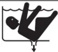
- Number of Suction Outlets Per Pump - Provide at least two (2) hydraulically-balanced main drains, with covers, as suction outlets for each circulating pump suction line. The centers of the main drains (suction outlets) on any one (1) suction line must be at least three (3) feet apart, center to center. See Figure 1.
- The system must be built to include at least two (2) suction outlets (drains) connected to the pump whenever the pump is running. However, if two (2) main drains run into a single suction line, the single suction line may be equipped with a valve that will shut off both main drains from the pump. The system shall be constructed such that it shall not allow for separate or independent shutoff or isolation of each drain. See Figure 1.
- More than one (1) pump can be connected to a single suction line as long as the requirements above are met.
- Water Velocity - The maximum water velocity through the suction outlet assembly and its cover for any suction outlet must not exceed the suction fitting assembly and it's cover's maximum design flow rate. The suction outlet (drain) assembly and its cover must comply with the latest version of ANSI/ASME A112.19.8, the standard for Suction Fittings For Use in Swimming Pools, Wading Pools, Spas, and Hot Tubs, or its successor standard, ANSI/APSP-16.
- If 100% of the pump's flow comes from the main drain system, the maximum water velocity in the pump suction hydraulic system must be six (6) feet per second or less, even if one (1) main drain (suction outlet) is completely blocked. The flow through the remaining main drain(s) must comply with the latest version of ANSI/ASME A112.19.8, the standard for Suction Fittings For Use in Swimming Pools, Wading Pools, Spas, and Hot Tubs, or its successor standard, ANSI/APSP-16.
- Testing and Certification - Suction outlet assemblies and their covers must have been tested by a nationally recognized testing laboratory and found to comply with the latest version of ANSI/ASME A112.19.8, the standard for Suction Fittings For Use in Swimming Pools, Wading Pools, Spas, and Hot Tubs, or its successor standard, ANSI/APSP-16.
- Fittings - Fittings restrict flow; for best efficiency use fewest possible fittings (but at least two (2) suction outlets).
- Avoid fittings which could cause an air trap.
- Pool cleaner suction fittings must conform to applicable International Association of Plumbing and Mechanical Officials (IAPMO) standards.
WARNING: Suction check valves and hydrostatic valves should not be used with this pump.
Figure 1. Number of Suction Outlets Per Pump
Section 2. Installation of the Digital Controller
2.1 Introduction
This document provides general instructions to install and operate the JEP-R Variable-Speed Digital Controller. The controller can be mounted to an electrical gang box (single, double, or triple) or to a fl at wall.
The instructions have been written with safety as the priority, and must be followed exactly. Read through the instructions completely before starting the procedure.
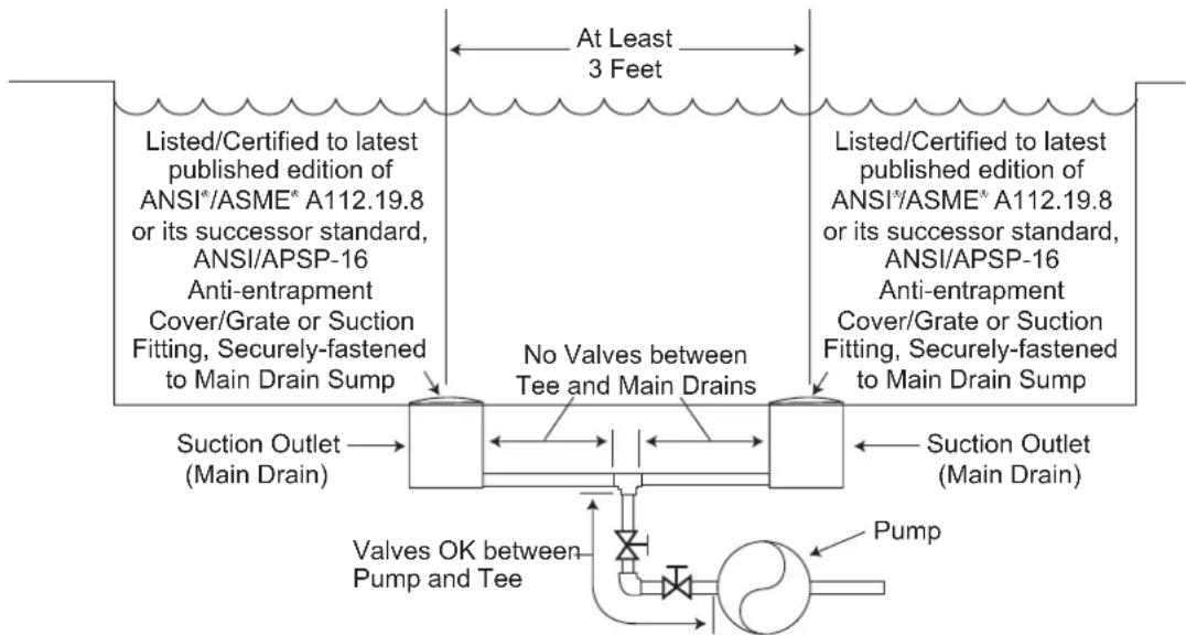
2.2 The Controller Panel
The controller panel provides both timed and manual speed controls for the Variable Speed Pumps.
Four (4) speeds are directly available on the panel, while four (4) additional speeds may be accessed via the MENU key.
Figure 2. JEP-R Controller Panel
The up and down keys are used to adjust the pump speed. The speed is saved as it is adjusted. No further action is required to save the new speed setting after adjustment. The selected speed can be saved and assigned to one of the speed buttons.
As shown in Figure 2, preset speed "A" is assigned to the "eStar" feature. Hence, it is intended to be assigned an energy-efficien fi ltration speed, as determined by the installer.
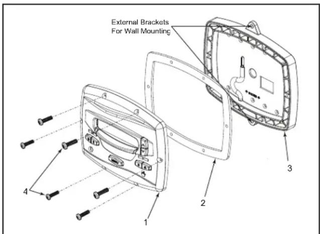
Figure 3. ControllerComponents
2.3 The Controller Components
The controller assembly contains the following components. See "Figure 3. Controller Components":
- Controller
- Mounting Gasket
- Backplate
- Six (6) Screws
2.3.1 Additional materials
The following are required for the installation of the controller and must be supplied by the installer:
- A minimum of two (2) fasteners to mount the controller back plate to a wall or electrical box. The fasteners should be suitable for the surface where the controller is to be remotely mounted.
- A high-voltage disconnect switch, as required by the National Electrical Code ^® (NEC ^® ), within line of sight of the pump.
2.4 Installation of the Backplate onto an Electrical Box

CAUTION
Do not expose the user interface to direct sunlight. Too much direct sunlight will darken the LCD screen, and it will no longer be readable.
- Turn off the pump at the control panel.
- Turn off all electrical power to the pump at the main junction box or at the circuit breaker providing electrical power to the pump.

WARNING
ELECTRICAL SHOCK HAZARD
Turn off all switches and the main breaker in the ePump electrical circuit before starting the procedure. Failure to comply may cause a shock hazard resulting in severe personal injury or death.
- Carefully detach the backplate from the controller by removing the six (6) screws from the front of the controller. Do not tug on the cable that is attached to the backplate in order to avoid damage to the cable or terminal block.
- The backplate has nine (9) mounting holes to choose from. Only drill out the plastic film from the holes to be used. See "Figure 3. Controller Components".
- Secure the backplate to the box using the screws that came with the electrical box.
2.5 Installation of the Backplate on a Flat Wall

CAUTION
Do not expose the user interface to direct sunlight. Too much direct sunlight will darken the LCD screen, and it will no longer be readable.
- Turn off the pump at the control panel.
- Turn off all electrical power to the pump at the main junction box or at the circuit breaker providing electrical power to the pump.

WARNING
ELECTRICAL SHOCK HAZARD
Turn off all switches and the main breaker in the ePump electrical circuit before starting the procedure. Failure to comply may cause a shock hazard resulting in severe personal injury or death.
- A minimum of two (2) fasteners (installer supplied) are required when installing to a flat wall to hold the controller securely.
- The backplate has two (2) mounting holes on the top and bottom. By using the external mounting holes, you do not need to remove the backplate from the controller. See "Figure 3. Controller Components".
- Mark the hole locations on the wall and use the fasteners to secure the backplate to the wall.
2.6 Connection to Jandy Pro Series variable-speed Pump
IMPORTANT
The installer must TURN ON switches 1 and 2 at the pump when connected to the variable-speed controller.
The following steps provide the procedure for installing the controller to a Jandy ^® variable speed pump.
- Turn off all switches and the main breaker that supplies power to the pump.
- Disassemble JEP-R controller from the backplate by removing the six screws. See "Figure 3. Controller Components".

WARNING
ELECTRICAL SHOCK HAZARD
Turn off all switches and the main breaker in the ePump electrical circuit before starting the procedure. Failure to comply may cause a shock hazard resulting in severe personal injury or death.
- Remove the cover of the pump junction box.
- Feed the RS-485 cable into the fitting.
NOTE The controller uses a four-wire RS-485 interface to communicate with the ePump.
- Unplug the RS-485 connector from the pump.
- Attach the four (4) wires in the RS-485 cable to the RS-485 connector. Make sure the colors match the positions on the connector. See "Figure 4. Wiring the Controller to the Variable Speed Pump"
- Connect the RS-485 connector back into the pump.
- Set the DIP switch settings for the pump controller with the 1 and 2 in the ON position and 3 and 4 in the OFF position. See "Figure 4. Wiring the Controller to the Variable Speed Pump".
- Turn on all switches and the main breaker feeding power to the pump.
- Verify the operation of the controller. If the controller displays FAULT PUMP NOT CONNECTED, re-check the wiring and the DIP switch address setting on the pump.
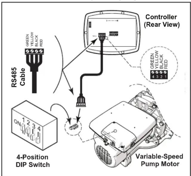
Figure 4. Wiring the Controller to the Variable Speed Pump
2.7 Variable Speed Pump Switch Settings
For the ePump™, the VS-FHP2.0 pump and the VSPHP27, the 4-position or 5-position dip switch is located at the rear of the pump, as shown in "Figure 4. Wiring the Controller to the Variable Speed Pump"
This dip switch serves two functions, it determines what type of control will be used with the pump and it selects the pump address. The SW 1 (switch 1) and SW 2 are turned ON if the pump is to be controlled by a JEP-R
controller or OFF if the pump is to be controlled by the AquaLink ^® RS, AquaLink PDA or AquaLink Z4. See "Table 1. DIP Switch Settings".
The controller allows speeds "★" through "4" to operate via remote contact closures (switch or relay). Speed "4" operates differently than the other three. See "2.10 Remote Closure 4 Behavior".
- Turn off all switches and the main breaker that supplies power to the variable-speed pump.
WARNING
ELECTRICAL SHOCK HAZARD
Turn off all switches and the main breaker in the ePump electrical circuit before starting the procedure. Failure to comply may cause a shock hazard resulting in severe personal injury or death.
- Connect one side of the remote contact closure to the COMMON terminal on J3 REMOTE CONTROL connector of the controller. See "Figure 5. Connect to Remote Contacts"
| Pump Function | Pump Address | DIP Switch Setting |
| 1 2 3 | 4 5 | | | |
| VS-FHP 1.0 | Factory Default N/A ON ON OFF OFF ON | | | | |
| JEP-R N/A ON ON OFF OFF ON | | | | |
| AquaLink® RS AquaLink PDA | PUMP 1 OFF | OFF OFF OFF ON | | | |
| PUMP 2 OFF | OFF ON OFF ON | | | |
| PUMP 3 OFF | OFF OFF ON ON | | | |
| PUMP 4 OFF | OFF ON ON ON | | | |
| ePump, ^TM VS PlusHP, and VS-FHP2.0 | Factory Default N/A OFF OFF OFF OFF N/A | | | | |
| JEP-R N/A ON ON OFF OFF N/A | | | | |
| AquaLink RS AquaLink PDA | PUMP 1 OFF | OFF OFF OFF N/A | | | |
| PUMP 2 OFF | OFF ON OFF N/A | | | |
| PUMP 3 OFF | OFF OFF ON N/A | | | |
| PUMP 4 OFF | OFF ON ON N/A | | | |
Table 1. DIP Switch Settings
- Connect the other side of the remote contact closure to INPUT 1, INPUT 2, INPUT 3, or INPUT 4 terminal on J3 REMOTE CONTROL connector of the controller, depending on which speed is to be controlled.
- Turn on all switches and the main breaker feeding power to the variable-speed pump.
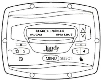
- Verify the operation of the contact closures. If the correct speed is activated when the closure is activated, the variable-speed pump starts, and the message REMOTE ENABLED appears on the controller display.
NOTE When starting the pump via a remote closure, the pump will first run at the priming speed for the priming duration, as set by the installer.
2.9 Remote Operation
Speeds activated via remote closures always override speeds that have been activated manually or via an internal timer program. When the pump is activated via a remote closure, the keypad is disabled and the message REMOTE ENABLED appears on the display.
The controller will remain in this state until the contact is opened. When more than one (1) contact closure occurs, the highest speed will take priority.
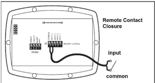
Figure 5. Connect to Remote Contacts
2.10 Remote Closure 4 Behavior
The behavior of speed "4" differs from manual operation when operated via a remote contact closure. As during manual operation, the turn-on time of remote closure 4 is immediate, and occurs at the same time as contact closure. The turn-off time, however, is delayed by 30 minutes.
In other words, when remote closure 4 is de-activated, the variable-speed pump will continue to run for 30 minutes, after which time the controller will turn off the variable-speed pump. The delay may be manually interrupted by pressing any speed key.
2.11 Remote Closure 4 Application - Booster Pump Support
The behavior of remote closure 4 may be used to allow an external timeclock fitted with a 20-minute “fireman’s switch” (e.g., Intermatic P/N 156T4042A) to properly control the variable-speed pump in conjunction with a booster pump.
NOTE Pump models JEP1.5, JEP2.0 allow for alternate remote closure, or auxiliary load options. Please see the pumps installation/owner's manual for more information.
Connection for Booster Pump Support:
- Turn off all switches and the main breaker that supplies power to the variable-speed pump.
WARNING
ELECTRICAL SHOCK HAZARD
Turn off all switches and the main breaker in the ePump ^™ electrical circuit before starting the procedure. Failure to comply may cause a shock hazard resulting in severe personal injury or death.
- Install the normally-closed fireman's switch to the timeclock assembly. (See timeclock manufacturer's instructions for details.)
- Connect the main timeclock contacts to the booster pump power input per the booster pump installation manual.
- Connect one side of the fireman's switch to the Controller at J3 REMOTE CONTROL, COMMON.
- Connect the other side of the fireman's switch to the controller at J3 REMOTE CONTROL, INPUT 4.
- Set the timeclock to the desired on/off times.
- Turn on all switches and the main breaker feeding power to the variable-speed pump.
- If the installation is working properly, the fireman's switch will open 20 minutes before the booster pump shuts down, the variable-speed pump will continue to run for 30 minutes, and the Controller will display PUMP WILL REMAIN ON FOR XX:XX, where XX:XX is the time remaining until variable-speed pump shutdown.
Section 3. User Operation of the Variable-Speed Controller
The variable-speed controller contains an advanced microcontroller that provides a simple yet sophisticated interface to operate your variable-speed pump for maximum efficiency and enjoyment of your pool.
The controller allows operation of the variable-speed pump in three ways: Manually, from built-in timers, and remotely via contact closures.
3.1 The Controller Interface
The controller interface panel provides both timed and manual speed controls for the variable-speed pump.
Four (4) speeds are directly available on the panel, while four additional speed presets may be accessed via the MENU key.
The up and down keys are used to adjust the pump speed. Speed is saved as it is adjusted. No further action is required to save the new speed setting after adjustment.
As shown below, preset speed "☆" is assigned to the eStar feature. Hence, it is intended to be assigned an energy-efficient filtration speed, as determined by the installer.
3.2 Basic Functions
The controller has two (2) operational modes: User Mode and Setup Mode.
User Mode
In the User Mode, the controller provides access to pump control options including:
- Manual start and stop of pump
- Pump speed setting
• Timeclock setup and operation
Setup Mode
The Setup Mode allows the user to configure the controller. Setup options include:
• Time-of-day setting
- Labeling of pump speeds
- Display light control
- Language selection
- Run duration
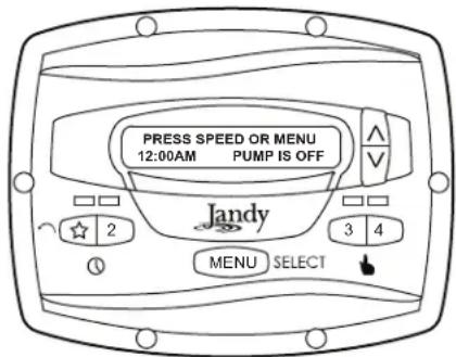
3.3 OFF Mode
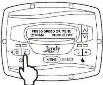
When the pump is off, the controller displays PRESS SPEED OR MENU/00:00 PUMP IS OFF, where 00:00 is the time-of-day clock.
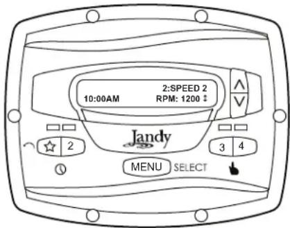
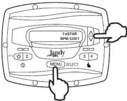
3.4 RUN Mode
When the pump is running, the controller displays N:LABEL/00:00 RPM:XXXX, where n:label is the number and label of the selected speed, 00:00 is the time-of-day clock, and xxxx is the pump speed.
3.5 Manual Start and Stop
Up to eight (8) speeds may be started from the controller. Manual operation of speeds "eStar" through "4" differs from manual operation of speeds "5" through "8".
NOTE When starting the pump, the pump will first run at the priming speed for the priming duration, as set by the installer.
Speeds eStar through 4
To start the pump manually running at speeds "eStar" through "4", press button "☆" through "4" corresponding to the desired speed. The associated LED will light red and the controller enters the RUN mode.

To stop the pump, press the button again. The associated LED will extinguish and the pump and controller will return to the OFF mode.
Speeds 5 through 8
To start the pump manually at speeds "5" through "8", press the MENU button. The controller displays SELECT PRESET/N:LABEL, where n:label is the number and label of the last selected speed "5" through "8".
Using the arrow keys, select the desired speed to activate, and then press MENU to enter RUN mode, starting the pump running at the selected speed.
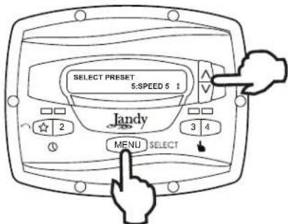
To stop the pump, press MENU. To exit without starting the pump, press any button "☆" through "4".
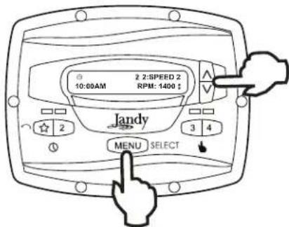
3.6 Pump Speed Setting
With the exception of preset "★", each speed may be adjusted while the pump is running in that speed mode. Preset "★" is reserved for the eStar function, and its speed is set by the installer.
To adjust the pump speed, the controller must be in the RUN mode. While in RUN mode, the controller displays the pump speed. Adjust the speed by pressing the up or down arrow keys. The speed is saved by the controller and will remain until changed again.
NOTE Pump speed is adjustable only within a certain range. The minimum and maximum limits of the range are set by the installer.
NOTE When used with a solar heat system, set speed to at least 3000 RPM and potentially up to 3450 RPM, based on the pump's head required to push the water up a minimum of 12-15 feet.
3.7 Timeclock Setup and Operation
NOTE The controller has a non-replaceable battery back-up that keeps time, programs, and speed settings when power is disconnected and should never require replacement.
The controller allows the user to create timed pump programs on pump speeds (presets) "☆" and "2". The two timers operate independently of each other, and may overlap in time if desired.
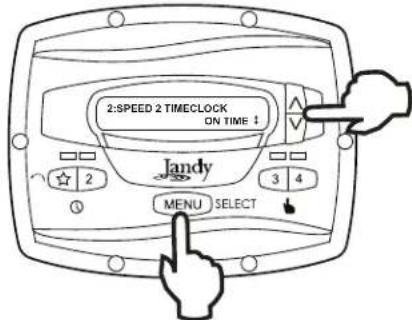
Timeclock Setup
Start the desired speed, "☆" or "2". Press MENU. The controller enters the Timeclock setup mode. Using the arrow keys, select ON TIME and press MENU. Set the desired pump turn-on time using the arrow keys and press MENU. The time is stored. Select OFF TIME using the arrow keys and press MENU. Set the desired pump turn-off time using the arrow keys and press MENU. The time is stored.
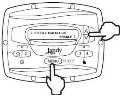
Using the arrow keys, select TIMECLOCK. Select ENABLE using the arrow keys. The program is now enabled to run. Press the speed button ("★" or "2") to return to the RUN mode.
Timeclock Operation
When the pump is stopped, the associated green LED will illuminate, indicating a timeclock program is enabled for that speed. If the pump has been turned on by the timeclock, the red LED will illuminate and a timeclock icon will show in the lower left hand corner of the display
If two (2) timed programs overlap, the program with the faster speed will take priority and run to completion. If the earlier-starting program is still active, it will resume operation.
The program off times never change, i.e., they are not ‘pushed-out’ in time when programs overlap. Timeclock programs may be prematurely stopped by stopping the pump manually from the keypad. This override is active until the program start time is reached again, at which time the timed program will start the pump as programmed.
NOTE When starting the pump via a timed program, the pump will first run at the priming speed for the priming duration, as set by the installer. If a program overlap occurs, the pump will immediately start at the program speed without priming first.
Manually Overriding a Timer Program
Timeclock programs may be prematurely stopped by pressing the active speed key. This override is active until the program start time is reached again, i.e., for 24 hours, at which time the timed program will start the pump as programmed.
Timer Overriding a Manual On
If the pump is started manually at a speed that has been programmed with a timer, the pump will be stopped by the timeclock at the programmed off time. A clock icon appears on the display when the timer has assumed control of the off time.
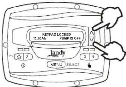
3.8 Keypad Lock
Press and hold both arrow keys for five (5) seconds to lock the keypad. To disable the keypad lock, repeat the procedure while the keypad is locked.
Section 4. Service Setup Options
The service setup menu allows the installer to set various operating parameters, view fault history, and restore factory defaults.
Parameters that may be modified and set in the service setup menu include:
- Priming speed and duration.
• Minimum and maximum pump speeds.
• "☆" cStar speed.
- Pump Freeze Protect operation.
4.1 Entering Service Setup
NOTE The controller must be in the OFF mode before entering the user setup mode. While in setup mode the controller will return back to the OFF mode after one (1) minute since the last key press.
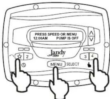
To enter the service setup menu, press and hold MENU, then press and hold the "☆" and speed "4" keys. Hold all three (3) keys down for five (5) seconds. To exit, press any speed button.
4.2 Minimum and Maximum Pump Speeds
These speeds are considered global settings across the entire controller, and create the range of allowable speed that may be sent to the variable-speed pump.
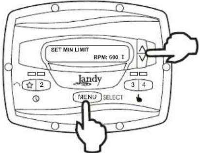
To set the minimum speed, from the service setup menu, select SET MIN LIMIT using the arrow keys. Press MENU. Using the arrow keys, set the minimum speed to the desired value. Press MENU to accept and store.
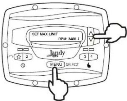
To set the maximum speed, from the service setup menu, select SET MAX LIMIT using the arrow keys. Press MENU. Using the arrow keys, set the maximum speed to the desired value. Press MENU to accept and store.
4.3 Load Defaults
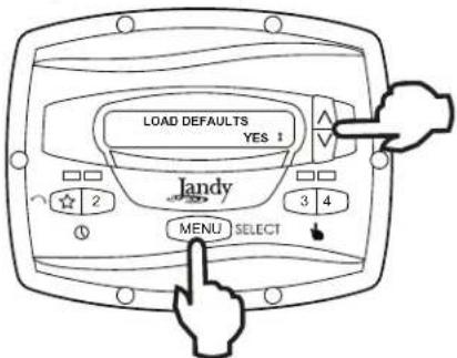
To restore factory default settings to the controller, from the service setup menu, select LOAD DEFAULTS. Press MENU. Using the arrow keys, select YES. Press MENU to restore factory default settings.
| Default Speeds |
| eStar 1750 RPM | |
| Speed 2 - 8 2750 RPM | |
| Priming Speed 2750 RPM | |
| Other Defaults |
| Freeze Protect Duration 30 min | |
| Priming Duration 3 min | |
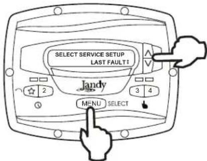
4.4 Last Fault
This feature shows on the top display line, the most recent unique fault message and on the bottom display line, the second-to-last unique fault message. If there is no entry for a fault, the display will show “*----*” on the corresponding line. To select last fault, from the service setup menu select LAST FAULT. Press MENU.
NOTE The fault messages are stored in non-volatile memory, and remain even with no power. To clear the fault history, press either arrow key.
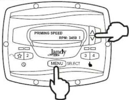
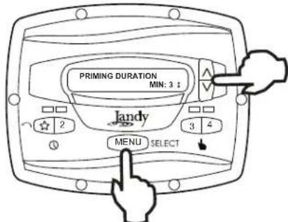
4.5 Priming Speed and Duration
The controller will command the variable-speed pump to operate at the priming speed for the priming duration specified (except during timer program overlaps or follow-on commands where the pump is not stopped before changing speeds). From the service setup menu, select PRIMING using the arrow keys. Press MENU.
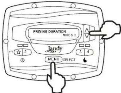
To set priming speed, select PRIMING SPEED using the arrow keys. Press MENU. Using the arrow keys, set the priming speed to the desired value. Press MENU to accept and store.
To set priming duration, select PRIMING DURATION using the arrow keys. Press MENU. Using the arrow keys, set the priming speed to the desired value in minutes from one (1) to five (5) minutes. Press MENU to accept and store.
4.6 eStar Speed
The "☆" speed is intended to be used as an energy-efficient setting that can be easily called-up by activating the eStar preset speed from the keypad or remote closure. After this speed has been determined by the installer, the eStar speed may be set as follows: From the service setup menu, select SET ESTAR SPEED. Press MENU. Using the arrow keys, set the speed to the desired value. Press MENU to accept and store.
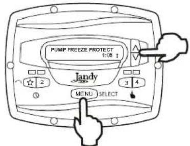
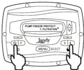
4.7 Pump Freeze Protect Operation
When enabled to do so, the controller monitors the temperature inside the pump and will activate the variable-speed pump at the eStar speed when the temperature approaches freezing. The run duration of the pump freeze protect operation is adjustable from 30 minutes to 8 hours, or may be disabled completely.
To set the pump freeze protect operation, from the service setup menu select PUMP FREEZE PROTECT. Press MENU. Using the arrow keys, set the duration to the desired value. To disable pump freeze protect, set the duration to 0:00. Press MENU to accept and store.
WARNING
Freeze protection is intended to protect equipment and plumbing for short periods of freezing only. It does this by activating the filtration pump and circulating the water to prevent freeze inside equipment or plumbing. Freeze protection does not guarantee that equipment will not be damaged by extended periods of freezing temperatures or power outages. In these conditions, the pool and spa should be shut down completely (e.g. drained of water and closed for the winter) until warmer weather exists.
The pump freeze protect run time may be interrupted by pressing a speed key, as follows:
Pressing the key "☆" once overrides the pump freeze protect run time, pressing it twice turns off the pump. Pressing other speed keys will override the pump freeze protect run time and activate the selected preset speed.
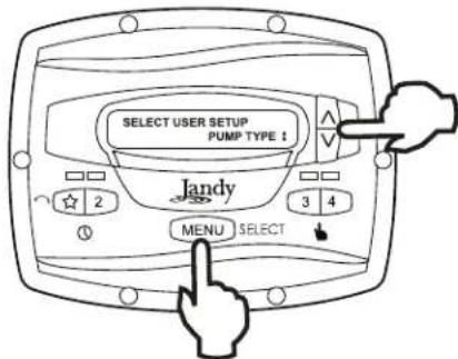
4.8 Selecting Pump Type
The controller may be used to operate various types of pumps. It is important to select the correct pump type at this menu item to ensure proper controller operation.
From the setup menu, select PUMP TYPE. Press the MENU button to display the currently selected pump type. Using the arrow keys, choose the pump type that matches the type of the installed pump. Refer to the pump manual for information regarding the pump type.
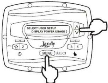
4.9 Display Power Usage
The controller can alternately display the variable-speed pump power usage while the pump is in operation and the controller is in Run Mode.
To enable the power display feature, from the service setup menu select DISPLAY POWER USAGE. Press MENU to select. Using the arrow keys, select YES. Press MENU to accept and store.
To disable the power display feature, from the service setup menu select DISPLAY POWER USAGE. Press MENU to select. Using the arrow keys, select NO. Press MENU to accept and store.
Section 5. User Set Up Options
NOTE The controller must be in the OFF mode before entering the user setup mode. While in setup mode the controller will return back to the OFF mode after one (1) minute since the last key press.
When in setup mode, speed keys "★" through "4" are used as 'escape' or exit keys while navigating the setup menu.
To enter the setup mode, press and hold the MENU button for five (5) seconds. The controller displays SELECT USER SETUP. Using the arrow keys, select the desired setup item to change.
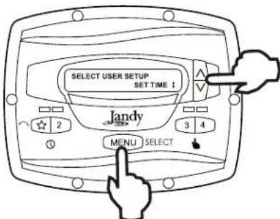
5.1 Setting Time-of-Day
From the Setup menu, select SET TIME. Press the MENU button to display the currently-set time. Using the arrow keys, adjust to the desired time. Press MENU to save your setting.
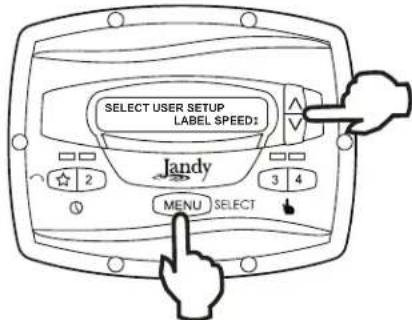
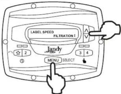
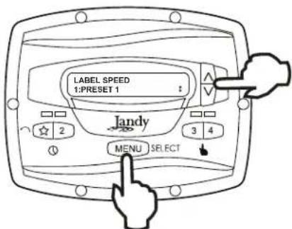
5.2 Labeling Speeds
The controller comes from the factory with pre-programmed labels or names for the preset speeds. The labels may be changed as desired to suit your particular installation.
Two (2) types of labels are provided by the controller:
- General Labels - selected from a list
- Custom Labels - created by the user
From the setup menu, scroll to LABEL SPEED and press MENU. The SELECT SPEED screen is displayed. Press the MENU button to display the
currently selected speed. Using the arrow keys, choose the speed to be changed. Press MENU to select. The controller displays SELECT LABEL TYPE. Select GENERAL or CUSTOM as desired using the arrow keys.
5.3 General Labels
Using the arrow keys, select a general label from the list to assign to the speed. Press MENU to assign the label to the speed.
5.4 Custom Labels
In the custom label mode, the controller displays a flashing cursor at the character position to be changed. Using the arrow keys, change the character as desired. Press MENU to accept the change and advance to the next character position. Press any speed key "★" through "4" to return to the previous cursor position.
Continue this procedure until the end of the label is reached. The new label is saved when MENU is pressed at the last character position.
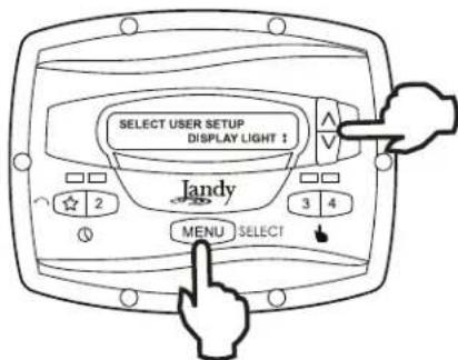
5.5 Display Light Control
The controller's display is equipped with a backlight to aid viewing in low light conditions.
From the setup menu, select DISPLAY LIGHT. Press MENU. Using the arrow keys, select the desired operating mode for the display backlight:
LIGHT OFF: Turn off display backlight.
LIGHT ON: Turn on display backlight.
2 MIN TIMEOUT: Turn on display backlight, with automatic turn-off after two (2) minutes since the last key press.
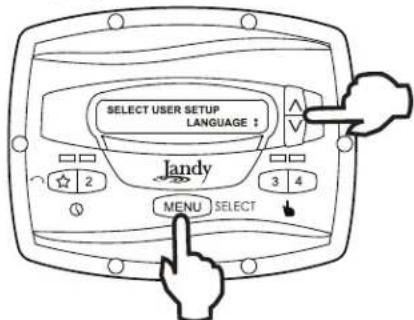
5.6 Language Selection
From the setup menu, select LANGUAGE using the arrow keys. Press MENU. Using the arrow keys, select the desired language. Press MENU to save the selection.
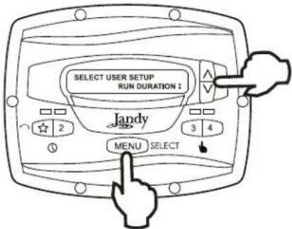
5.7 Run Duration (Speeds 3 and 4 Only)
Speeds "3" and "4" may be programmed to run for a specified duration after being manually started. This run duration is programmable from 30 minutes to eight (8) hours, in increments of 30 minutes. A setting of 0:00 disables the run duration feature, allowing the speed to run indefinitely.
From the setup menu, select RUN DURATION. Press MENU. Using the arrow keys, select the speed to be programmed. Press MENU. Set the desired run duration for the speed using the arrow keys. Press MENU to accept.
5.8 Password Protect
Entry into the USER SETUP MENU may be restricted by the setting of a four-digit password.
NOTE: There is a 10-minute delay period from the last key press to the password becoming active. This allows additional, protected operations to be performed temporarily after setting the password.
From the setup menu, select PASSWORD PROTECT and press the MENU key.
The menu will verify if the user wishes to set a password. Using the arrow keys, select YES then press the MENU key.
Using the arrow keys, select a value for each password digit. Press the MENU key to set each digit.
When the last password digit is set, the password is stored and the controller displays *PASSWORD ACCEPTED* and returns to the OFF mode.

Changing a Password
From the setup menu, select SET PASSWORD and press the MENU key. The controller displays CHANGE PASSWORD? Using the arrow keys, select CHANGE and press the MENU key.
The current password is displayed. Using the arrow keys, select a value for each password digit. Press the MENU key to set each digit. When the last password digit is set, the password is stored and the controller displays *PASSWORD ACCEPTED* and returns to the OFF mode.

Clearing A Password
From the setup menu, select SET PASSWORD and press the MENU key. The controller displays CHANGE PASSWORD? Using the arrow keys, select CLEAR and press the MENU key. The password is cleared and the controller returns to the OFF mode.
Section 6. Menu Flow Chart
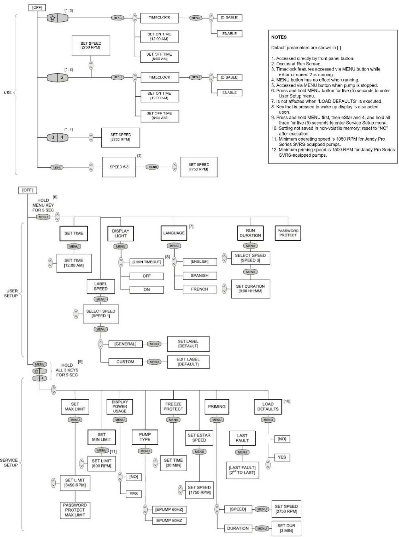
NOTES
Default parameters are shown in [ ].
- Accessed directly by front panel button.
- Occurs at Run Screen.
- Timeclock features accessed via MENU button while eStar or speed 2 is running.
- MENU button has no effect when running.
- Accessed via MENU button when pump is stopped.
- Press and hold MENU button for five (5) seconds to enter User Setup menu.
- Is not affected when "LOAD DEFAULTS" is executed.
- Key that is pressed to wake up display is also acted upon.
- Press and hold MENU first, then eStar and 4, and hold all three for five (5) seconds to enter Service Setup menu.
- Setting not saved in non-volatile memory; reset to "NO" after execution.
- Minimum operating speed is 1050 RPM for Jandy Pro Series SVRS-equipped pumps.
- Minimum priming speed is 1500 RPM for Jandy Pro Series SVRS-equipped pumps.
Zodiac Pool Systems Canada, Inc.
2115 South Service Road West, Unit 3 Oakville, ON L6L 5W2
1-888-647-4004 | www.ZodiacPoolSystems.ca
Zodiac Pool Systems, Inc.
2620 Commerce Way, Vista, CA 92081
1.800.822.7933 | www.ZodiacPoolSystems.com
©2017 Zodiac Pool Systems, Inc. ZODIAC ^® is a registered trademark of Zodiac International,
S.A.S.U., used under license. All trademarks referenced herein are the property of their respective owners.
H0412200 Rev J
Figure 3. Componentes del controlador
4.3 Cargar ajustes predeterminados
Zodiac Pool Systems Canada, Inc.
2115 South Service Road West, Unit 3 Oakville, ON L6L 5W2
1-888-647-4004 | www.ZodiacPoolSystems.ca
Zodiac Pool Systems, Inc.
2620 Commerce Way, Vista, CA 92081
1.800.822.7933 | www.ZodiacPoolSystems.com
©2017 Zodiac Pool Systems, Inc. ZODIAC® es una marca registrada de Zodiac International, S.A.S.U.,
Zodiac Pool Systems Canada, Inc.
2115 South Service Road West, Unit 3 Oakville (ON) L6L 5W2
+ 1 (888) 647-4004 | www.ZodiacPoolSystems.ca
Zodiac Pool Systems, Inc.
2620 Commerce Way, Vista, CA 92081
1 800 822-7933 | www.ZodiacPoolSystems.com