2300PSI - Pressure washer Generac - Free user manual and instructions
Find the device manual for free 2300PSI Generac in PDF.
User questions about 2300PSI Generac
0 question about this device. Answer the ones you know or ask your own.
Ask a new question about this device
Download the instructions for your Pressure washer in PDF format for free! Find your manual 2300PSI - Generac and take your electronic device back in hand. On this page are published all the documents necessary for the use of your device. 2300PSI by Generac.
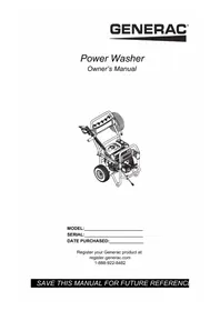
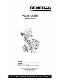
USER MANUAL 2300PSI Generac
Electric Power Washer
Owner's Manual

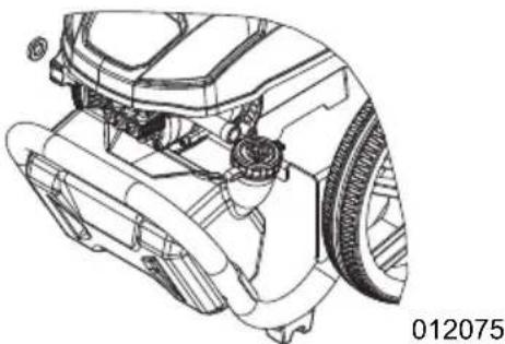
natural_image
Line drawing of a modern pressure cooker with attached hoses and wheels (no text or symbols)MODEL:
SERIAL:
DATE PURCHASED:
Register your Generac product at:
register.generac.com
1-888-922-8482
Section 1 Introduction and Safety 1
Introduction 1
Safety Rules 1
Safety Symbols and Meanings ..... 1
Section 2 General Information and
Setup 3
Know Your Power Washer .... 3
Remove Contents from Carton ..... 3
Assembly 3
Connections 4
Water Supply 4
Connect Water Supply 4
Connect High-Pressure Hose and Lance 4
Spray Gun 5
Nozzles 5
Select correct nozzle for task. ..... 5
Connect Power Supply 6
Electrical Plug 6
Safety Devices 6
Section 3 Operation ....7
Operation and Use Questions .....7
Before Starting Unit 7
Power Washer Start-Up ....7
Power Washer Shut Down .....7
Apply Detergent 7
Rinsing 8
Clean Detergent Siphoning Tube ....8
Section 4 Maintenance and
Troubleshooting 9
Maintenance 9
Maintenance Schedule 9
Preventive Maintenance 9
Storage 10
Troubleshooting ....11
Notes 12
COMPLIES WITH
CAN ICES-001 (B)/NMB-001 (B)
WARNING
CANCER AND REPRODUCTIVE HARM
www.P65Warnings.ca.gov.
(000393a)
Section 1 Introduction and Safety
Introduction
Read This Manual Thoroughly

WARNING
Consult Manual. Read and understand manual completely before using product. Failure to completely understand manual and product could result in death or serious injury. (000100a)
If any section of this manual is not understood, contact Generac Customer Service at 1-888-436-3722 (1-888-GENERAC), or visit www.generac.com for starting, operating, and servicing procedures. The owner is responsible for proper maintenance and safe use of the unit.
SAVE THESE INSTRUCTIONS for future reference. This manual contains important instructions that must be followed during placement, operation, and maintenance of the unit and its components. Always supply this manual to any individual that will use this unit, and instruct them on how to correctly start, operate, and stop the unit in case of emergency.
The information in this manual is accurate based on products produced at the time of publication. The manufacturer reserves the right to make technical updates, corrections, and product revisions at any time without notice.
Safety Rules
The manufacturer cannot anticipate every possible circumstance that might involve a hazard. The alerts in this manual, and on tags and decals affixed to the unit, are not all inclusive. If using a procedure, work method, or operating technique that the manufacturer does not specifically recommend, verify that it is safe for others and does not render the equipment unsafe.
Throughout this publication, and on tags and decals affixed to the unit, DANGER, WARNING, CAUTION, and NOTE blocks are used to alert personnel to special instructions about a particular operation that may be hazardous if performed incorrectly or carelessly. Observe them carefully. Alert definitions are as follows:
DANGER
Indicates a hazardous situation which, if not avoided, will result in death or serious injury.
(000001)
!WARNING
Indicates a hazardous situation which, if not avoided, could result in death or serious injury.
(000002)
CAUTION
Indicates a hazardous situation which, if not avoided, could result in minor or moderate injury.
(000003)
NOTE: Notes contain additional information important to a procedure and will be found within the regular text of this manual.
These safety alerts cannot eliminate the hazards that they indicate. Common sense and strict compliance with the special instructions while performing the action or service are essential to preventing accidents.
Safety Symbols and Meanings

DANGER
Electrocution. In the event of electrical accident, immediately shut power OFF. Use non-conductive implements to free victim from live conductor. Apply first aid and get medical help. Failure to do so will result in death or serious injury. (000145)

DANGER
Electrocution. Water contact with a power source, if not avoided, will result in death or serious injury.
(000104)

DANGER
Electrocution. DO NOT use the unit if electrical cord is cut or worn through. Doing so will result in death or serious injury.
(000263a)

WARNING
Electrocution. Potentially lethal voltages are generated by this equipment. Render the equipment safe before attempting repairs or maintenance. Failure to do so could result in death or serious injury.
(000187)

WARNING
Fluid Injection. This machine produces high-pressure fluid streams that can pierce skin. Fluid injection could result in death or serious injury. (000106b)

WARNING
Vision Loss. Eye goggles are required to be worn when using this machine. Failure to wear eye goggles could result in permanent vision loss. (000101)

WARNING
Moving Parts. Keep clothing, hair, and appendages away from moving parts. Failure to do so could result in death or serious injury. (000111)

WARNING
Risk of Falling. Use of machine creates wet areas and trip hazards. Be aware of work area conditions. A fall could result in death or serious injury. (000112)

WARNING
Risk of Falling. Do not use this machine or any components on elevated surfaces. Doing so can result in a fall, serious injury, or death. (000114)

WARNING
Consult Manual. Read and understand manual completely before using product. Failure to completely understand manual and product could result in death or serious injury. (000100a)

WARNING
Moving Parts. Do not wear jewelry when starting or operating this product. Wearing jewelry while starting or operating this product could result in death or serious injury. (000115)

WARNING
Personal injury. Risk of fluid injection. Do not aim spray gun at people, animals, electrical devices, or fragile items. Keep out of reach of children. Failure to do so could cause death or serious injury. (000117c)
WARNING
Personal Injury / Equipment Damage. Place wand/gun in holster and verify that handle is locked into place before moving. Failure to do so could result in death, serious injury, or equipment damage. (000244a)
CAUTION
Protective clothing. Eye and hearing protection along with protective clothing (pants and shoes) are recommended when using this machine. Failure to wear these items could result in permanent injuries. (000740)
Extension Cords
Only use extension cords that are approved for outside use identified by "ACCEPTABLE FOR USE WITH OUTDOOR APPLIANCES; STORE INDOORS WHILE NOT IN USE". Only use extension cords having an electrical rating not less than the rating of the product. DO NOT use damaged extension cords. Examine extension cord before using and replace if damaged. Do not abuse extension cord and do not yank on any cord to disconnect it. Keep cord away from heat and sharp edges. Always disconnect the extension cord from the receptacle before disconnecting the pressure washer from the extension cord.
Section 2 General Information and Setup
Know Your Power Washer

WARNING
Consult Manual. Read and understand manual completely before using product. Failure to completely understand manual and product could result in death or serious injury. (000100a)
Remove Contents from Carton
-
Remove and verify carton contents prior to assembly. Carton contents should contain one each of the following:
-
Main Unit
- Handle
- Billboard
- Spray Gun
• Lance - Hose
- Parts Bag (includes)
- Owner's Manual
- Warranty
- Hose Hook
- Gun Hook
- Nozzle Bag
- Hardware Bag
- Hex Wrench
- Open End Wrench
- Nozzle Cleaning Tool
-
Call Generac Customer Service at 1-888-GENERAC (1-888-436-3722) with the unit model and serial number for any missing carton contents.
-
Record model, serial number, and date of purchase on front cover of this manual.
| 2300 psi Specifications | |
| Max Pressure 2300 | psi at initial discharge per CSA internal pressure testing |
| Working Pressure | 1700 psi |
| Max Flow | 1.2 GPM with gun in soap dispensing configuration |
| 2700 psi Specifications | |
| Max Pressure 2700 | psi at initial discharge per CSA internal pressure testing |
| Working Pressure | 2200 psi |
| Max Flow | 1.2 GPM with gun in soap dispensing configuration |
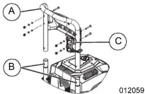
Assembly
- See Figure 2-1. Snap handle (A) to unit using the two detent buttons (B).
- Attach billboard to left side of handle and the gun hook (C) to right side of handle with supplied screws, washers, lock washers and nuts.
NOTE: Use 45mm screws (short) on billboard side and the 55mm screws (long) on gun hook side.
text_image
A B C 012059Figure 2-1. Attach Handle
- See Figure 2-2. Attach hose hook (A) to back of billboard by compressing hook sides and inserting ends into mounting holes.
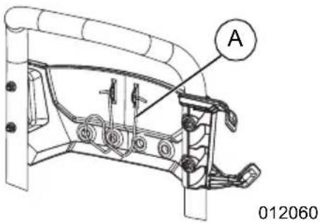
text_image
A 012060Figure 2-2. Attach Hose Hook
-
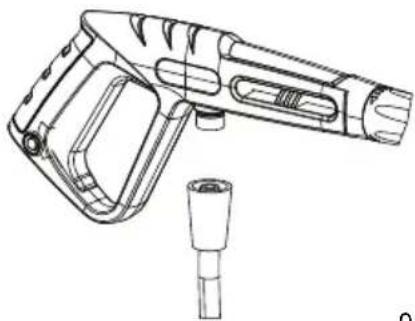
See Figure 2-3. Insert gun and lance into gun holster (A). Hang hose on hose hook (B). Hang electric cord on rear of shroud (D).
-
Insert nozzles into billboard grommets (C).
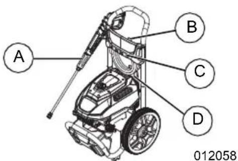
text_image
A B C D 012058Figure 2-3. Hang Electric Cord, Holster Gun and Lance
Connections

WARNING
Consult Manual. Read and understand manual completely before using product. Failure to completely understand manual and product could result in death or serious injury. (000100a)
Call Generac Customer Service at 1-888-GENERAC (1-888-436-3722) for any assembly issues or concerns. Please have model and serial number available.
See Figure 2-4.
- Power Washer
- Water Supply Hose
- Water Supply
- Water Inlet
- High Pressure Hose
- Water Outlet
- Spray Gun
- Power Supply
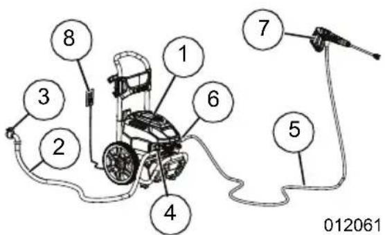
text_image
8 3 2 1 6 4 7 5 012061Figure 2-4. Connections
Water Supply
NOTE: DO NOT run unit without sufficient water supply. Failure to follow water supply requirements will void unit warranty.
Water supply must meet the following requirements:
• DO NOT siphon standing water for the water supply.
• Water temperature must be less than 100^ F ( 38^ C).
• Water supply hose length must not exceed 50 ft (15.2 m).
• Water must be greater than 2.5 gallons per minute (9.5 liters per minute) and no less than 20 psi (137.8 kPa).
- DO NOT use a one-way valve, vacuum breaker, or check valve in any part of the water supply.
Connect Water Supply
- Remove and discard shipping cap from the pump water outlet.
- Run water supply for 30 seconds prior to connection to eliminate debris.
- See Figure 2-5. Inspect inlet screen for debris. Clean screen or replace as necessary. DO NOT run power washer if inlet screen is damaged or missing.
natural_image
Technical line drawing of a mechanical assembly with no visible text or symbolsFigure 2-5. Inspect Inlet Screen
- See Figure 2-6. Connect water supply hose to unit and hand-tighten.
natural_image
Technical diagram of a car engine showing internal components and a directional arrow (no text or symbols)Figure 2-6. Connect Water Supply Hose
Connect High-Pressure Hose and Lance
- See Figure 2-7. Connect high-pressure hose to unit and hand-tighten.
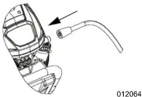
natural_image
Technical line drawing of a mechanical device with a curved pipe and component, no visible text or symbolsFigure 2-7. Connect High-Pressure Hose to Unit
- See Figure 2-8. Connect high pressure hose to gun and hand-tighten.
natural_image
Technical line drawing of a handheld device with a cylindrical connector (no text or symbols)012065
Figure 2-8. Connect High-Pressure Hose to Spray Gun
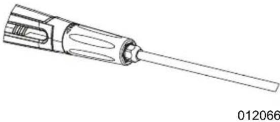
- See Figure 2-9. Connect threaded end of lance into spray gun.
natural_image
Technical line drawing of a screwdriver with a pointed tip and internal cavities (no text or symbols)Figure 2-9. Connect Lance
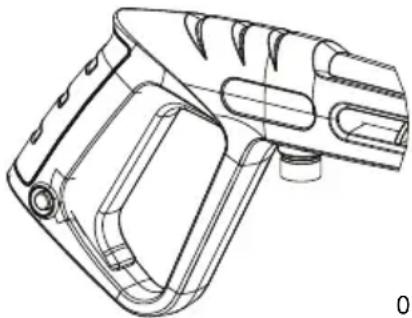
- Place spray gun and lance into gun holder.
Spray Gun
Become familiar with spray gun trigger and locking system prior to use.
- See Figure 2-10. With unit OFF, hold spray gun and squeeze trigger to learn how trigger mechanism and locking system can be activated and deactivated.
natural_image
Technical line drawing of a mechanical device with a pointed tip and mounting bracket (no text or symbols)Figure 2-10. Spray Gun (typical)
- Turn ON the water, and squeeze the trigger to purge the pump system of air.
Nozzles

!WARNING
Fluid Injection. This machine produces high-pressure fluid streams that can pierce skin. Fluid injection could result in death or serious injury. (000106b)
WARNING
Personal injury. Risk of fluid injection. Do not aim spray gun at people, animals, electrical devices, or fragile items. Keep out of reach of children. Failure to do so could cause death or serious injury. (000117c)
WARNING
Personal Injury. Do not adjust spray nozzles, valves, or hoses when pump engine is running. Doing so could result in death or serious injury. (000383)
CAUTION
Property damage. This nozzle can permanently damage work surfaces. Do not hold nozzle too close or in one position for a long time period.
(000125a)
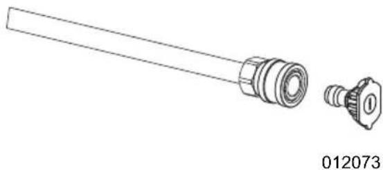
Select correct nozzle for task.
- See Figure 2-11. Pull back quick-connect collar and install nozzle.
- Release quick-connect collar to secure nozzle.
- Verify nozzle is locked in place.
natural_image
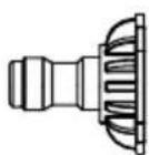
Technical line drawing of a mechanical component with a cylindrical shaft and flanged end (no text or symbols)Figure 2-11. Insert Nozzle
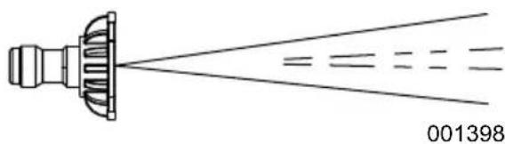
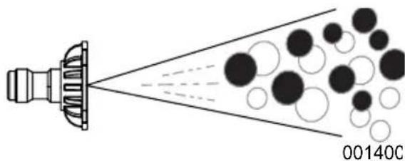
Blast Pressure Nozzle (Red)
MAXIMUM - Higher pressure and lower flow for stubborn or hard to reach surface such as second story surfaces, paint removal, oil stains, rust removal or other stubborn substances (tar, gum, grease, wax, etc.).
001396
Clean Pressure Nozzle (Yellow)
GENERAL - Medium pressure and medium flow for most all purpose cleaning such as home siding, brick patios, wood decks, driveways and sidewalks, garage floors, etc.
natural_image
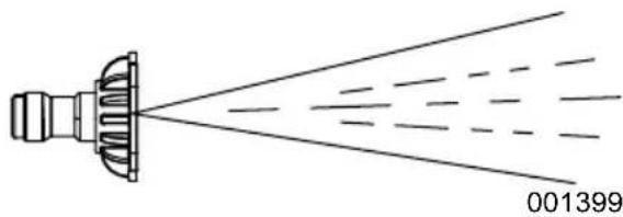
Diagram of a spray gun emitting liquid, showing spray nozzle and fan structure (no text or symbols)Wash Pressure Nozzle (Green)
DELICATE - Lower pressure and higher flow for gentle cleaning of cars/trucks, boats, RV's, patio furniture, lawn equipment, etc.
natural_image
Diagram of a spray gun emitting particles from a nozzle, labeled 001399 (no text or symbols on diagram)Detergent Nozzle (Black)
DETERGENT ONLY (BLACK), Only use power washer safe detergents/soaps to help break down stubborn dirt and grime on a variety of surfaces.
natural_image
Diagram of a spray gun emitting particles from a nozzle, with no visible text or symbolsConnect Power Supply

DANGER
Electrocution. Water contact with a power source, if not avoided, will result in death or serious injury.
(000104)

DANGER
Electrocution. DO NOT use the unit if electrical cord is cut or worn through. Doing so will result in death or serious injury.
(000263a)

WARNING
Electrocution. Never use an extension cord that is not rated for outdoor use. Doing so could result in death, serious injury, or equipment or property damage.
(000711a)
Connect unit to an isolated Ground Fault Circuit Breaker (GFCI) protected receptacle rated at 120 volts, 15 amps.
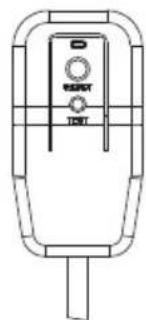
Electrical Plug
- Connect power washer to an isolated Ground Fault Circuit Breaker (GFCI) protected receptacle rated at 120 volts, 15 amps (minimum).
- See Figure 2-12. Test GFCI plug by pressing the Test button. The indicator light on the GFCI plug should not be illuminated.
- Reset GFCI plug by pressing the Reset button. The indicator light on the GFCI plug should illuminate.
natural_image
Line drawing of a portable phone with control panel (no text or symbols)011678
Figure 2-12. Test GFCI
NOTE: Contact customer service if the Test button does not turn off the indicator light, or if the Reset button does not turn on the indicator light. Do not use the product.
Safety Devices
- Thermal Sensor - A thermal sensor protects the motor against overloading. The machine will restart after the motor has cooled.
- Ground Fault Circuit Interrupter (GFCI) protection - This power washer is supplied with a ground-fault circuit interrupter (GFCI) built into the plug on the power supply. This device provides additional protection from risk of electrical shock. If the cord needs to be replaced, use identical replacement parts.
- Auto Shut-off - The unit will automatically shut off when the gun is not triggered.
- Auto Start-up - When the trigger is pressed the unit will run.
Section 3 Operation
Operation and Use Questions
Call Generac Customer Service at 1-888-GENERAC (1-888-436-3722) with questions or concerns about unit operation and maintenance.
NOTE: This power washer is equipped with a water flow sensor which will start or stop the unit. When the gun trigger is pulled, the unit motor will start. When the gun trigger is released, the water flow and the unit will stop to protect the motor from over heating. When the unit is ON but not in use, the hose and gun may slowly release pressure. The motor will periodically start to reestablish pressure in the hose and gun. This momentary starting is normal to the operation of the unit.
Before Starting Unit

DANGER
Electrocution. Water contact with a power source, if not avoided, will result in death or serious injury.
(000104)
- Verify all fittings and couplers are properly secured.
- Verify sufficient water supply is properly connected.
- Verify unit is secure on level ground.
- Verify unit is connected to power supply.
- Test plug GFCI function by depressing the Test button on the plug body. Indicator light on plug body should turn off. Press Reset to resume unit operation.
Power Washer Start-Up

WARNING
Vision Loss. Eye goggles are required to be worn when using this machine. Failure to wear eye goggles could result in permanent vision loss. (000101)

WARNING
Personal injury. Risk of fluid injection. Do not aim spray gun at people, animals, electrical devices, or fragile items. Keep out of reach of children. Failure to do so could cause death or serious injury.
(000117c)

WARNING
Fluid Injection. This machine produces high-pressure fluid streams that can pierce skin. Fluid injection could result in death or serious injury. (000106b)
NOTE: DO NOT run power washer without a sufficient water supply turned ON. Damage to equipment resulting from failure to follow this instruction will void warranty.
- Connect a sufficient water supply.
- Connect power cord to power supply.
- Turn power switch to ON. See Figure 3-1.
- Pull gun trigger to spray. Unit will automatically shut off when gun is not triggered.
natural_image
Technical line drawing of a mechanical component with a central knob and mounting holes (no text or symbols)Figure 3-1. Turn ON/OFF Switch
Power Washer Shut Down

WARNING
Fluid Injection. This machine produces high-pressure fluid streams that can pierce skin. Fluid injection could result in death or serious injury. (000106b)
IMPORTANT: Spray gun traps high-pressure water, even when motor is stopped and water is disconnected. Always point spray gun in safe direction, and squeeze spray gun trigger to release high-pressure. Engage trigger lock when not in use.
- Turn power switch OFF.
- Turn water supply OFF.
- Squeeze spray gun trigger and release high-pressure water.
- Engage trigger lock.
Apply Detergent

WARNING
Fluid Injection. This machine produces high-pressure fluid streams that can pierce skin. Fluid injection could result in death or serious injury. (000106b)
WARNING
Personal injury. Risk of fluid injection. Do not aim spray gun at people, animals, electrical devices, or fragile items. Keep out of reach of children. Failure to do so could cause death or serious injury.
(000117c)
NOTE: DO NOT use caustic liquid with power washer. Use ONLY power washer safe detergents. Follow all manufacturer's instructions on the detergent label.
Apply detergent as follows:
- Turn power switch OFF.
- Squeeze spray gun trigger and release high-pressure water and engage trigger lock.
- See Figure 3-2. Pull back quick-connect collar and install black detergent nozzle.
- Release quick-connect collar to secure nozzle.
- Verify nozzle is locked in place.

natural_image
Technical line drawing of a mechanical component with a cylindrical shaft and flanged end (no text or symbols)Figure 3-2. Attach Detergent Applicator
- See Figure 3-3. Prepare detergent solution as required by job in on-board detergent bottle.
NOTE: Ensure chemical injection hose is placed through the chemical tank cap and is submerged in the chemical solution.
natural_image
Technical line drawing of a mechanical assembly with gears and housing (no text or symbols)Figure 3-3. Fill On-board Tank
- Turn power switch ON.
- Apply detergent starting at the lower portion of area to be washed and work upward using long, even, overlapping strokes.
NOTE: See Rinsing. Rinse heavily soiled areas with water before applying detergent.
NOTE: Use a brush to lightly scrub heavily soiled areas after applying detergent.
IMPORTANT: Flush the detergent siphoning system after each use. Contact Customer Service with questions.
Rinsing

WARNING
Risk of Falling. Use of machine creates wet areas and trip hazards. Be aware of work area conditions. A fall could result in death or serious injury. (000112)

WARNING
Risk of Falling. Do not use this machine or any components on elevated surfaces. Doing so can result in a fall, serious injury, or death. (000114)
- Remove detergent applicator from spray gun.
- Point spray gun in safe direction and squeeze trigger to flush remaining detergent from system.
- Install high pressure nozzle.
- Keep spray gun a safe distance from area you plan to spray.
- Spray gun may kick back when using high pressure spray. To avoid injury, firmly grasp spray gun with both hands.
- Apply a high-pressure spray to a small area and then inspect surface for damage. If no damage is found, continue rinsing.
- Start at top of area to be rinsed, working down with same overlapping strokes as used for cleaning.
Clean Detergent Siphoning Tube
Flush detergent siphoning tube after each use before turning unit OFF.
- Rinse detergent tank thoroughly and fill with clean water.
- Flush for 1-2 minutes.
- Remove detergent applicator.
- Turn unit OFF.
- Point spray gun in a safe direction, squeeze spray gun trigger to release retained high water pressure. Engage trigger lock.
After Each Use
DO NOT allow water to remain in unit for long periods of time. Sediments or minerals can deposit on pump parts and freeze pump. Follow these procedures after every use:
- Shut unit OFF.
- Turn water supply OFF.
- Point spray gun in a safe direction, and squeeze trigger to relieve trapped pressure.
-
Disconnect hoses from spray gun and high-pressure outlet on pump. Drain water from hoses, spray gun, and lance. Use a rag to wipe off components.
-
Store unit in a clean, dry area.
NOTE: If storing for more than 30 days, see Storage.
Section 4 Maintenance and Troubleshooting
Maintenance
Regular maintenance will improve performance and extend motor/equipment life.
Power washer warranty does not cover items subjected to operator abuse or negligence. To receive full warranty value, operator must maintain power washer as instructed in this manual, including proper storage as detailed in Storage.
NOTE: Call Generac Customer Service at 1-888-GENERAC (1-888-436-3722) with questions about component replacement.
NOTE: All required service and adjustments should be completed as detailed in Maintenance Schedule.
Maintenance Schedule
NOTE: Adverse conditions will require more frequent service.
| Before Each Use |
| Inspect/clean water inlet screen* |
| Inspect high-pressure hose** |
| Inspect detergent siphoning hose/filter |
| Inspect spray gun and assembly for leaks |
| Clean debris |
| Test GFCI plug with Test/Reset buttons** |
| Inspect electrical cord** |
| * Clean if clogged. Replace if perforated or torn. ** Do not operate unit if damaged. |
Preventive Maintenance
Dirt or debris can cause improper operation and equipment damage. Clean power washer daily or before each use. Inspect all cooling air openings on power washer.
- Use a damp cloth to wipe exterior surfaces clean.
- DO NOT insert any objects through cooling air openings.
- Use a soft bristle brush to loosen caked on dirt.
- Use a vacuum to pick up loose dirt and debris.
Inspect and Clean Inlet Screen
Inspect inlet screen on pump water inlet. Clean clogged screen and replace screen if damaged.
Inspect High-Pressure Hose
High-pressure hoses can develop leaks from wear, kinking, or abuse. Inspect hoses before each use. Inspect for cuts, leaks, abrasions, bulging, and damage or movement of couplings. If these conditions exist, replace hose immediately.
NOTE: DO NOT repair high-pressure hose. Replace with hose that meets or exceeds maximum pressure rating of unit.
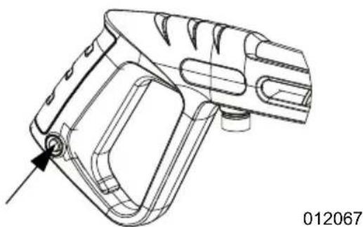
Inspect Spray Gun
NOTE: Replace spray gun immediately if it fails any test steps.
natural_image
Technical line drawing of a mechanical device component (no text or symbols)012067
Figure 4-1. Test Spray Gun (typical)
- Verify spray gun hose connection is secure.
- Squeeze and release trigger.
NOTE: Trigger should spring back into place and lock when released.
Nozzle Maintenance

WARNING
Fluid Injection. This machine produces high-pressure fluid streams that can pierce skin. Fluid injection could result in death or serious injury. (000106b)
A pulsing sensation felt when squeezing spray gun trigger may be caused by excessive pump pressure. Typical causes of excessive pump pressure are nozzle clog or restriction. Immediately clean nozzle as follows:
- Turn unit and water supply OFF.
NOTE: Keep high-pressure hose connected to pump and spray gun while system is pressurized.
- Relieve spray gun water pressure.
- Engage trigger lock.
- Pull back quick-connect collar and remove nozzle.
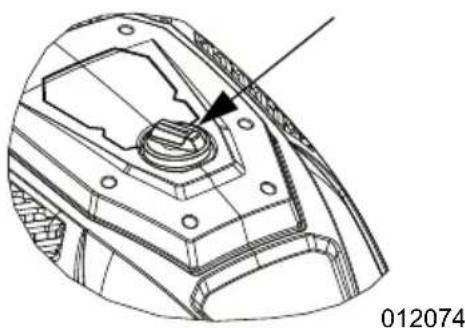
- See Figure 4-2. Use supplied nozzle cleaning tool to remove debris.
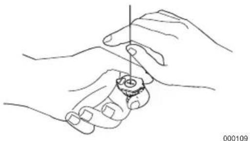
natural_image
Line drawing of two hands holding a small object with a vertical line above, no text or symbols presentFigure 4-2. Remove Debris
- See Figure 4-3. Remove lance from spray gun and back flush thoroughly.
- Install lance on spray gun.
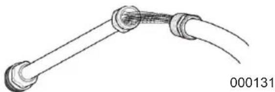
natural_image
Line drawing of a pipe fitting with two ends and a coiled cable (no text or symbols)Figure 4-3. Back Flush Lance
- Install nozzle onto lance.
- Verify hose is connected to pump water inlet, and high-pressure hose is connected to spray gun and pump.
- Turn water ON.
- Turn power switch ON.
- Test power washer by operating with nozzle.
Storage
General
- DO NOT place a storage cover on a hot power washer. Allow unit to cool to room temperature before storage.
- Cover unit with a suitable protective, moisture resistant cover.
- Store unit in a clean and dry area.
Prepare Pump for Storage
NOTE: If not using power washer for more than 30 days, prepare pump for storage.
Protect unit from freezing temperatures. Failure to do so will permanently damage pump and render unit inoperable. Freeze damage is not covered under warranty.
Protect unit from freezing temperatures as follows:
- Turn unit OFF.
- Turn water supply OFF.
- Point spray gun in a safe direction, and squeeze trigger to relieve trapped pressure.
- Let unit cool.
- Disconnect hose from spray gun and high-pressure outlet on pump. Drain water from hose, spray gun, and lance. Use a rag to wipe off components.
- Empty pump of all remaining liquids.
- Winterize pump with RV-antifreeze (alcohol free antifreeze). This minimizes freeze damage and lubricates pistons and seals.
- Store unit in a clean and dry area.
Troubleshooting
| Problem Cause Correction | ||
| Pump fails to produce pressure, has erratic pressure, chattering, loss of pressure, low water volume. | 1. Water inlet is obstructed.2. Inadequate water supply.3. Inlet hose kinked or leaking.4. Water supply is over 100°F (37.8°C).5. High-pressure hose is obstructed, or leaks.6. Spray gun leaks.7. Nozzle is obstructed.8. Water seals worn.9. Pump is faulty. | 1. Clean inlet screen.2. Provide adequate water flow.3. Straighten inlet hose, patch leak.4. Provide cooler water supply.5. Clear obstructions or replace hose.6. Replace spray gun.7. Clean nozzle.8. Contact Customer Service.9. Contact Customer Service. |
| Detergent fails to mix with spray. | 1. Detergent applicator obstructed or cracked.2. High-pressure nozzle installed. | 1. Clean or replace applicator.2. Remove high-pressure nozzle. |
| Unit begins to smolder or smoke. | 1. Overheated, overloaded or damaged motor. | 1. Turn unit OFF and unplug power supply. Contact Customer Service. |
| Unit will not start. 1. Unit is not plugged into power supply or not plugged in correctly.2. Extension cord is too long or wire size too small.3. Main voltage supply too low.4. GFCI plug is tripped. | 1. Check power supply, socket and fuse.2. Remove extension cord.3. Check for sufficient voltage supply.4. Reset GFCI plug. | |
| Motor shuts down during operation. | 1. Extension cord is too long or wire size too small.2. Unit overheated. | 1. Remove extension cord.2. Turn unit OFF and let cool. |
| Pump does not reach necessary pressure. | 1. Water inlet filter is clogged.2. Pump is sucking air from hose connections3. Nozzle is worn.4. Pump is faulty. | 1. Clean water inlet filter.2. Confirm connections and locking ring are tight.3. Replace nozzle.4. Contact Customer Service. |
Notes
Part No. A0001299447 Rev. A 03/02/2021
©2021 Generac Power Systems, Inc.
All rights reserved
Specifications are subject to change without notice.
No reproduction allowed in any form without prior
written consent from Generac Power Systems, Inc.

Generac Power Systems, Inc.
S45 W29290 Hwy. 59
Waukesha, WI 53189
1-888-GENERAC (1-888-436-3722)
www.generac.com
natural_image
Line drawing of a pressure cooker with attached hoses and wheels (no text or symbols)MODELO:
SERIE:
FECHA DE COMPRA:
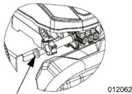
natural_image
Technical line drawing of a mechanical assembly with no visible text or symbols012062
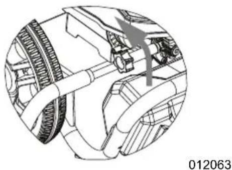
natural_image
Technical diagram of a mechanical assembly showing gears and shafts (no text or labels)012063
natural_image
Technical line drawing of a mechanical device with a curved pipe and connector (no text or symbols)012064
natural_image
Technical line drawing of a handheld device with handle and connector (no text or symbols)natural_image
Technical line drawing of a screwdriver with a pointed tip and internal cavities (no text or symbols)natural_image
Technical line drawing of a mechanical device with a pointed tip and mounting bracket (no text or symbols)natural_image
Technical line drawing of a mechanical component with a cylindrical shaft and flanged end (no text or symbols)Figura 2-11. Insertar boquilla
natural_image
Diagram of a spray gun emitting liquid, showing spray nozzle and fan structure (no text or symbols)natural_image
Diagram of a spray gun emitting particles from a nozzle, showing spray direction (no text or symbols)natural_image
Diagram showing a spray gun emitting particles from a nozzle, with no text or symbols present.natural_image
Line drawing of a handheld electronic device with control buttons (no text or symbols)011678
Figura 2-12. Probar GFCI
natural_image
Technical line drawing of a mechanical component with a central knob and mounting holes (no text or symbols)natural_image
Technical line drawing of a mechanical component with threaded ends and a separate inset showing a pin (no text or symbols)natural_image
Technical line drawing of a mechanical assembly with gears and housing (no text or symbols)natural_image
Technical line drawing of a mechanical device component (no text or symbols)012067
natural_image
Line drawing of two hands holding a small object with a vertical line above (no text or symbols)000109
natural_image
Simple line drawing of two connected cables with a bulbous connector (no text or symbols)000131
©2021 Generac Power Systems, Inc.
natural_image
Line drawing of a pressure cooker with attached hoses and wheels (no text or symbols)MODÈLE :
N° DE SÉRIE : ____
DATE D'ACHAT : ____
natural_image
Technical line drawing of a mechanical assembly with no visible text or symbolsnatural_image
Technical line drawing of a mechanical assembly with no visible text or symbolsnatural_image
Technical line drawing of a mechanical component with an arrow indicating direction (no text or symbols)natural_image
Technical line drawing of a handheld device with handle and connector (no text or symbols)natural_image
Technical line drawing of a screwdriver with a pointed tip and internal cavities (no text or symbols)natural_image
Technical line drawing of a mechanical device with no visible text or symbolsnatural_image
Technical line drawing of a mechanical component with a cylindrical shaft and flanged end (no text or symbols)Figure 2-11. Insertion de la buse
Buse ultra haute pression (Rouge)
natural_image
Diagram of a spray gun emitting light rays from a central component, labeled 001398 (no text or symbols on diagram itself)natural_image
Diagram of a spray gun emitting spray from a nozzle, showing incident and emitted rays (no text or symbols)natural_image
Diagram showing a spray gun emitting particles from a nozzle, with no text or symbols present.natural_image
Line drawing of a handheld electronic device with control panel and ports (no text or symbols)011678
Figure 2-12. Test GFCI
natural_image
Technical line drawing of a mechanical component with a central knob and mounting holes (no text or symbols)natural_image
Technical line drawing of a mechanical component with a cylindrical shaft and flanged end (no text or symbols)natural_image
Technical line drawing of a mechanical assembly with no visible text or symbolsnatural_image
Technical line drawing of a mechanical device component (no text or symbols)012067
natural_image
Line drawing of two hands holding a small object with a vertical line above, no text or symbols presentnatural_image
Simple line drawing of a pipe fitting with two ends and a coiled cable (no text or symbols)©2021 Generac Power Systems, Inc.