
VT-Solar v.1.5 - Lighting Generac - Free user manual and instructions
Find the device manual for free VT-Solar v.1.5 Generac in PDF.

| Product type | Mobile solar LED lighting tower |
| Brand | Generac |
| Model | VT-Solar v.1.5 |
| Category | Lighting |
| Number of LED floodlights | 4 |
| Power per LED floodlight | 100 W |
| Total lighting power | 400 W |
| Solar panel type | Monocrystalline |
| Number of solar panels | 3 |
| Power per solar panel | 400 W |
| Battery bank voltage | 48 V |
| Battery bank capacity | 120 Ah |
| Battery type | 12 V 120 Ah (8 units) |
| Inverter/charger | 48 V / 3000 W / 35-50 A |
| Telescopic mast | 6 galvanized steel sections |
| Deployment winch | Manual, capacity 900 kg |
| Stabilizers | 2 rotating with jacks |
| Wheels | 2 tires ST175/80D13 |
| Hitch | 2-inch ball |
| Estimated total weight | Approximately 1500 kg |
| Power supply | Solar + rechargeable batteries |
| Electrical protection | 20 A circuit breakers, fuses, grounding |
| Control panel | With switches, potentiometer and indicators |
| Recommended use | Outdoor, construction sites, events |
| Manual language | French, English (translation available) |
| Technical support | Phone: 1-800-926-9768, website |
Frequently Asked Questions - VT-Solar v.1.5 Generac
User questions about VT-Solar v.1.5 Generac
0 question about this device. Answer the ones you know or ask your own.
Ask a new question about this device
Download the instructions for your Lighting in PDF format for free! Find your manual VT-Solar v.1.5 - Generac and take your electronic device back in hand. On this page are published all the documents necessary for the use of your device. VT-Solar v.1.5 by Generac.
USER MANUAL VT-Solar v.1.5 Generac
natural_image
Technical line drawing of a mobile radar or antenna system with wheels and control panel (no text or symbols)MODEL NUMBER: ____
SERIAL NUMBER:
DATE PURCHASED:
! WARNING
CANCER AND REPRODUCTIVE HARM
www.P65Warnings.ca.gov.
(000393a)
! WARNING
Breathing diesel engine exhaust exposes you to chemicals known to the State of California to cause cancer and birth defects or other reproductive harm.
- Always start and operate the engine in a well-ventilated area.
- If in an enclosed area, vent the exhaust to the outside.
- Do not modify or tamper with the exhaust system.
- Do not idle the engine except as necessary. For more information go to
www.P65Warnings.ca.gov/diesel. (000394)
Introduction
This parts manual was prepared based on the information available at the time of publication and is subject to change without notice. Generac Mobile Products reserves the right to change parts at any time. To check whether a revised parts manual is available, contact Generac Mobile Products.
DO NOT MODIFY or use this equipment for any application other than which it was designed for. To keep your equipment fully operational, it is suggested you maintain a stock of commonly used maintenance or service parts. A recommended spare parts list can be found in the back of this manual. To order service parts, please go to www.generacmobileproducts.com or call Generac Mobile Products.

WARNING
Consult Manual. Read and understand manual completely before using product. Failure to completely understand manual and product could result in death or serious injury.(000100a)
WARNING
Environmental Hazard. Always recycle batteries at an official recycling center in accordance with all local laws and regulations. Failure to do so could result in environmental damage, death, or serious injury. (000228)
GENERAC MOBILE PRODUCTS LLC
215 Power Drive • Berlin, WI 54923 U.S.A.
Phone: 920-361-4442
FAX: 920-361-4416
Toll Free: 1-800-926-9768
www.generacmobileproducts.com
For technical or parts QUESTIONS, contact Generac Mobile Products Technical Service at 1-800-926-9768.
Engine Make:
Engine Serial Number:
Engine Model Number: ____
This Page Intentionally Left Blank
Table of Contents
Introduction......iii
Parts Manual Instructions....1
Decals....2
Control Panel Assembly (1 of 2)....4
Control Panel Assembly (2 of 2)....6
Base Assembly 8
Fairing Assembly 10
Door Assembly 12
Inverter Door Assembly 14
Command Box Door Assembly 16
Mast Assembly 18
4 x 100W LED Lamp Assembly....20
Stabilizer Assembly 22
Plug Group CEE 230V....24
Rechargeable Battery Pack....26
Solar Panel Assembly 28
Trailer Assembly 30
Document Holder Group....32
Inverter/Charger Group 34
Recommended Spare Parts - Misc. 36
[Non-Text]
[Non-Text]
[Non-Text]
[Non-Text]
[Non-Text]
[Non-Text]
[Non-Text]
[Non-Text]
[Non-Text]
[Non-Text]
[Non-Text]
[Non-Text]
[Non-Text]
[Non-Text]
[Non-Text]
[Non-Text]
[Non-Text]
[Non-Text]
[Non-Text]
[Non-Text]
[Non-Text]
[Non-Text]
[Non-Text]
[Non-Text]
[Non-Text]
[Non-Text]
[Non-Text]
[Non-Text]
[Non-Text]
[Non-Text]
[Non-Text]
[Non-Text]
[Non-Text]
[Non-Text]
[Non-Text]
[Non-Text]
[Non-Text]
[Non-Text]
[Non-Text]
[Non-Text]
[Non-Text]
[Non-Text]
[Non-Text]
[Non-Text]
[Non-Text]
[Non-Text]
[Non-Text]
vi
[Non-Text]
[Non-Text]
[Non-Text]
[Non-Text]
[Non-Text]
vi
vi
[Non-Text]
[Non-Text]
[Non-Text]
[Non-Text]
[Non-Text]
[Non-Text]
[Non-Text]
[Non-Text]
[Non-Text]
[Non-Text]
[Non-Text]
[Non-Text]
[Non-Text]
Parts Manual Instructions
Product illustrations are only representations. Products supplied may vary from the illustrations in this parts manual. Parts not shown in the illustration are indicated by a double dash (--) in the item column.
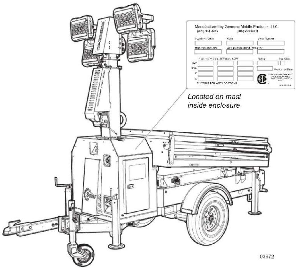
Please be prepared to provide the following information when ordering replacement parts: model number, serial number (on unit serial tag), part number, purchase order number (if applicable), shipping address, shipping method.
Refer to the illustration below to locate the unit ID tag on the unit. Important information, such as the unit serial number, model number, and tire loading information are found on these tags. Record the information from these tags so it is available if the tags are lost or damaged. When ordering parts or requesting assistance, you may be asked to provide this information.
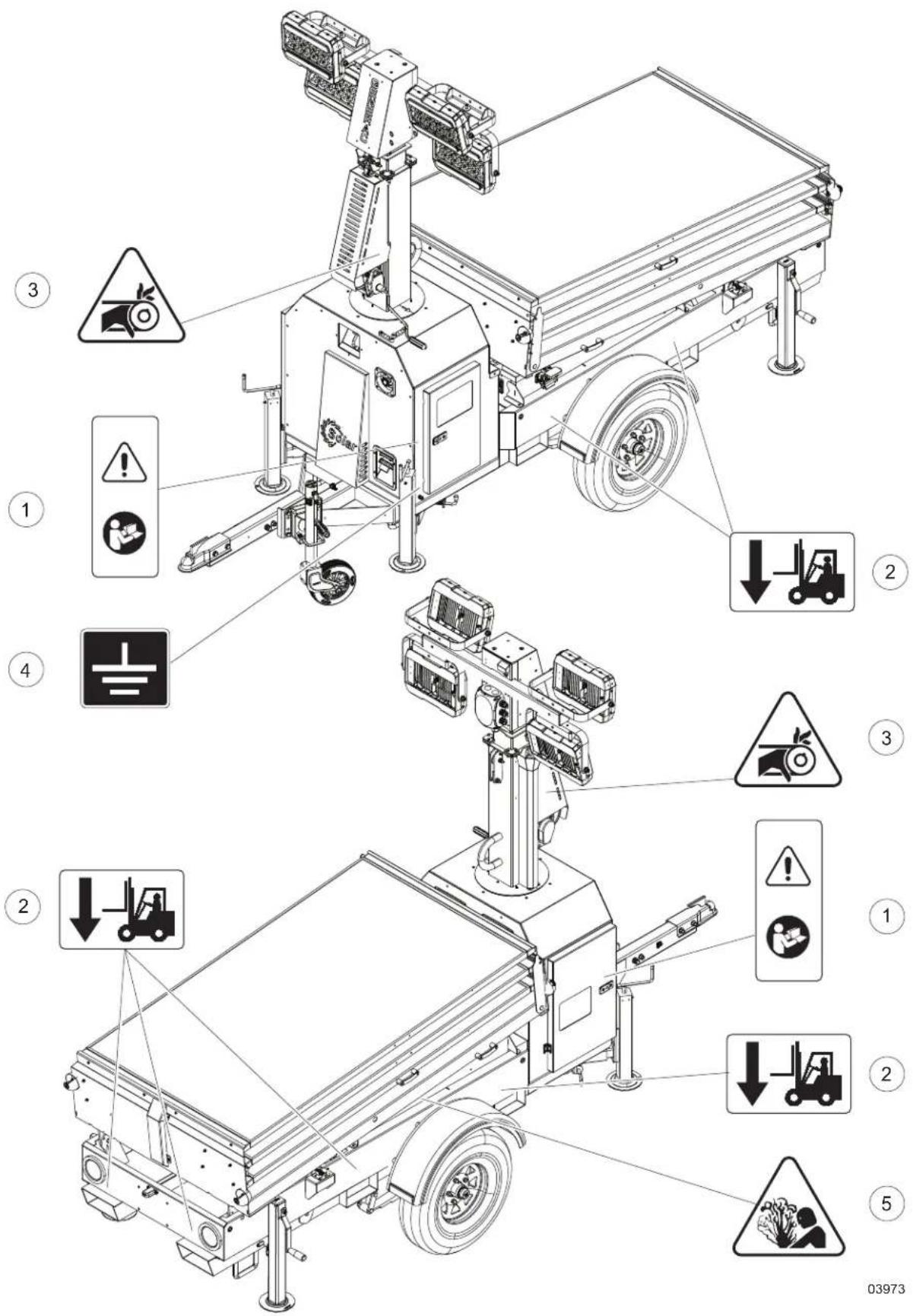
Item Part No. Qty Description Notes
1 A0000763414 DECAL-READ THE MANUAL
2 A0000763413 DECAL-FORKLIFT
3 A0000762098 DECAL-WARNING- PINCH POINT
4 A0001584693 STICKER-GROUNDING-LT
5 A0000762097 DECAL- DANGER POSSIBLE SPILLAGE OF
CORROSIVE SUBSTANCES
03974
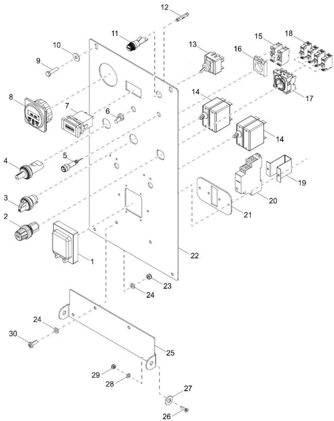
Item Part No. Qty Description Notes
1 A0004896018 1 PROTECTION CASE - 2 MODULES
2 A0004898554 1 ROTATIVE SWITCH 4 - POSITION
3 A0004896147 1 STABLE ON-OF-ON LEVER SELECTOR
4 A0004898529 1 ROTARY POTENTIOMETER
5 A0004898548 1 12V RED INDICATOR LAMP -LED (ROUND)
6 A0004895998 1 RUBBER CAP FOR SWITCH
7 A0004947355 1 110V 60HZ HOUR METER WITH 48X24 ADAPTER
8 A0004900038 1 BATTERY MONITOR BMV-700 9-90VDC
9 4 SCREW, M6 X 25
10 4 WASHER, 10.5 X 20 X .2 SS
11 A0000717234 1 6.3X32 FUSE HOLDER
12 A0004896150 1 10A 250V 6.3 X 32 UL/CSA CERAMICS FUSE
13 A0004898537 1 3 POSITION 3-WAY DIVERTER
14 A0005459530 2 BREAKER-20A 250V
15 A0000717241 2 NO AUXILIARY CONTACT FOR IMPULSE BUTTON
16 A0000717246 1 BUTTON BASE
17 A0004898553 1 4 MODULES SUPPORT FOR 4-POS SWITCH
18 A0004898556 4 NO CONTACT FOR 4 - POS. SELECTOR SWITCH
19 A0004894212 1 BRACKET FOR 1P CIRCUIT BREAKER
20 A0004896106 1 RELAY, 12V DC
21 A0004895989 1 CIRCUIT BREAKER SUPPORT 1P
22 A0004898549 1 FRONT PLATE WITH MANUAL MAST
23 4 NUT, M10 ATB
24 A0004407524 8 WASHER, M10 FLAT
25 A0004897194 1 FRONT PANEL SUPPORT - BLACK
26 2 SCREW, M5 X 20
27 2 WASHER, M10 X 20 X .2 PLASTIC
28 A0004407515 2 WASHER-M8-FLAT
29 2 NUT, M8 ATB
30 4 SCREW, PAN HEAD M X 16
03975
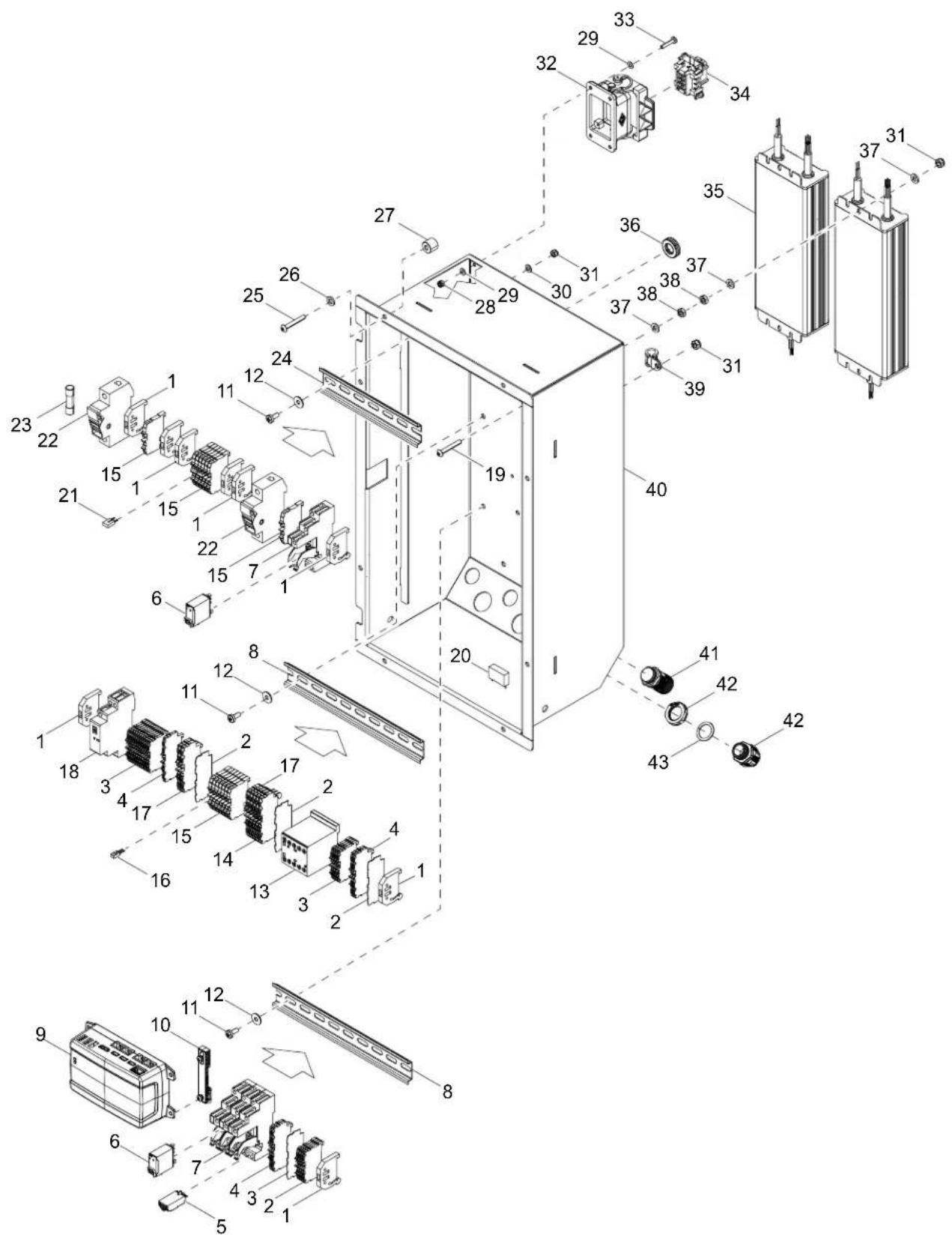
Item Part No. Qty Description Notes
1 A0000717530 6 STOP TERMINAL BOARD (PHOENIX TYPE 3-35)
2 A0004897211 19 FEED THROUGH TERMINAL 2 CONDUCTORS 1.0MM GRAY
3 A0004897223 3 INTERMEDIATE END PLATE 4 CONDUCTORS
4 A0004897213 3 FEED THROUGH TERMINAL 4 CONDUCTORS 1.0MM GRAY
5 A0004896036 3 S86 12/24V BI-FUNCTION TIMER MODULE
6 A0000215359 3 END AND INTERMEDIATE PLATE (4MMQ CON)
7 A0000745227 4 SOCKET, RELAY 1C
8 A0004896008 2 DIN RAIL, 35 X 235
9 A0004898543 1 SYSTEM CONTROLLER
10 A0004897190 2 DIN 35 ADAPTER SMALL
11 6 SCREW, M4 X 30 PHILLIPS PAN
12 6 WASHER, PL 8,4 X 24 X 2 SS
13 A0004896035 1 CONTACTOR, 4 PIN 20A 12V
14 A0001079365 5 FEED THROUGH TERMINAL 4 CONDUCTORS 2.5MM YEL/GRN
15 A0000717538 14 FEED THROUGH TERMINAL 2 CONDUCTORS 2.5MM GRAY
16 A0000717549 1 CONNECTION, TERMINAL BOARD 2.5MM 2-WAY
17 A0001079364 2 FEED THROUGH TERMINAL 4 CONDUCTORS 2.5MM GRAY
18 A0000718230 1 CONTACTOR, MODULAR 12V AC/DC 25A
19
8 SCREW, M4 X 25 TCCIC C4.8
20 A0000216436 1 CAPACITOR, 100V
21 A0004947357 1 CONNECTION, TERMINAL BOARD 1MM 2-WAY
22 A0001793683 2 FUSE HOLDER, MODULAR1P 10 X 38
23 A0004896037 2 FUSE, 10A 500V 10 X 38
24 A0004896008 1 DIN RAIL, 35 X 170
25 8 SCREW TBEI M5 X 25 C 8.8
26 15 WASHER, M6 FLAT SS
27 A0004896113 8 SPACER, M6 X 13MM
28 8 NUT, M6 HEX NYLOCK
29 6 WASHER, M4 FLAT SS
30 6 WASHER, M8 FLAT SS
31 6 NUT, M8 NYLOCK
32 A0004896016 1 BULKHEAD MOUNT, 6 POS W/LEVER
33 4 SCREW, M4 X 20 PHILLIPS PAN
34 A0004895993 1 INSERT, FEMALE 6 POS
35 A0004897252 2 DRIVER LED 90-305VAC 320W 48V
36 A0004897205 3 MEMBRANE, CABLE GLAND 21MM DIA
37 12 WASHER, M6 FLAT SS
38 8 NUT, M6 HEX
39 A0004894200 1 CLAMP. M6
40 A0004898578 1 ASSEMBLED COMMAND BOX NA - BLACK
41 A0004896149 2 PANEL CONNECTOR, 5 PIN M20
42 A0004896131 1 CABLE GLAND, M20 X 1.5 W/RING NUT
43 A0000764115 1 GASKET, M20
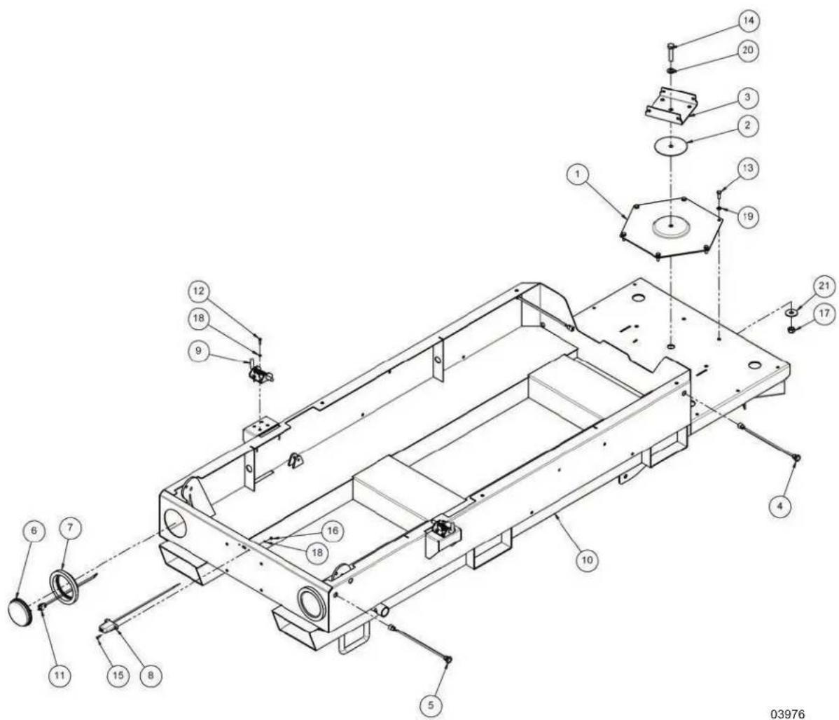
Item Part No. Qty Description Notes
| 1 A0004898586 1 LOWER THRUST BEARING FLANGE | |||
| 2 A0000763418 1 DISC 14X120X2 FOR THRUST BEARING | |||
| 3 A0000763447 1 MAST FLANGE FOR THRUST BEARING | |||
| 4 A0004898587 2 COMPLETE LIGHT, AMBER SIDE MARKER | |||
| 5 A0004898595 2 COMPLETE LIGHT, RED SIDE MARKER | |||
| 6 A0004898602 2 LIGHT RED REAR TAIL/TURN | |||
| 7 A0004898604 2 GROMMET, REAR LIGHT, RUBBER 4.5 IN | |||
| 8 | A0004898608 | 1 | LIGHT, LICENSE PLATE |
| 9 | A0004898613 | 2 | COMPACT SPRING BOLT WITH LOCK |
| 10 | A0004898619 | 1 | ASSEMBLED BASE- BLACK |
| 11 | A0004898630 | 2 | PLUG, REAR LIGHT, 3-WIRE WITH GROMMET (UL) |
| 12 | 8 | SCREW TE M5 X 20 CL 8.8 | |
| 13 | 6 | SCREW TE M8 X 25 CL 8.8 | |
| 14 | 1 | SCREW TE M14 X 60 CL 8.8 | |
| 15 | 2 | SCREW TCEI M5 X 15 CL8.8 | |
| 16 | 2 | NUT ATB B M5 | |
| 17 | 6 | NUT ATB B M14 | |
| 18 | 2 | WASHER PN 5,3 X 10 X 1 SS | |
| 19 | A0004407515 6 WASHER PN 8,4 X 16 X 1,6 SS | ||
| 20 | 1 | WASHER PN 15 X 28 X 2,5 SS | |
| 21 | 6 | WASHER PL 15 X 44 X 3 SS | |
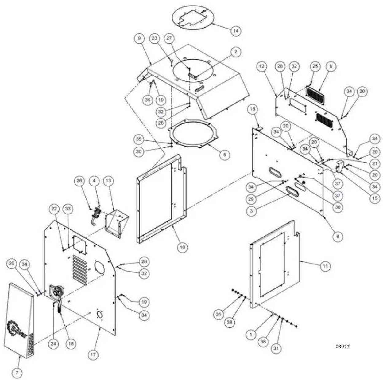
Item Part No. Qty Description Notes
| 1 A0000748380 1 M8 X 50 BRASS THREADED BAR | |
| 2 A0000216115 2 SPIRIT LEVEL | |
| 3 A0004898631 2 GASKET WITH METAL CORE AND U FORM | |
| 4 A0000216289 1 SPRING BOLT WITH PINS | |
| 5 A0000763384 1 FLANGE, MAST GUIDE | |
| 6 A0004898632 2 200 X 100 BLACK PLASTIC GRID | |
| 7 A0004898633 1 FRONT COVER | |
| 8 A0004898637 1 COVER PANEL | |
| 9 A0004898641 1 TOP PANEL FOR MANUAL MAST | |
| 10 A0004898643 1 RIGHT SIDE PANEL FOR MANUAL MAST | |
| 11 A0004898645 1 LEFT SIDE PANEL FOR MANUAL MAST | |
| 12 A0004898651 1 REAR PANEL FOR MANUAL MAST | |
| 13 A0004898715 1 SUPPORT BOX -SPRING BOLT | |
| 14 A0004898719 1 MAST ENCLOSURE DISK | |
| 15 A0004898722 1 LEFT BRACKET SUPPORT TILTING CARRIAGE | |
| 16 A0004898729 1 RIGHT BRACKET SUPPORT TILTING CARRIAGE | |
| 17 A0004898735 1 FRONT PANEL MANUAL MAST W/ 120V SOCKET | |
| 18 A0004898737 1 STOP BUTTON 2NC WIRING & 5P CONNECTOR | |
| 19 | 8 SCREW TE M6X20 CL 8.8 |
| 20 | 12 SCREW TBEI M6X20 CL 10.9 |
| 21 | 1 SCREW TBEI M8X20 CL 10.9 |
| 22 | 5 SCREW TBEI M5 X 30 CL10.9 |
| 23 | 6 SCREW TTQS M8 X 20 CL 4.8 |
| 24 | 4 SCREW TCCIC M4 X 14 CL 4.8 |
| 25 | 8 SCREW TSIC M4X16 CL 4.8 |
| 26 | 4 SCREW TSIC M5 X 16 CL 4.8 |
| 27 | 4 SCREW TSIC M4X25 CL 4.8 |
| 28 | 16 NUT ATB B M4 |
| 29 | 1 NUT ATB B M6 |
| 30 | 7 NUT ATB B M8 |
| 31 | 4 NUT N M8 - BRASS |
| 32 | 16 WASHER PN 4,3 X 9 X 0,8 SS |
| 33 | 5 WASHER PN 5, 3 X 10 X 1 SS |
| 34 | 22 WASHER PN 6,4X12X1,6 SS |
| 35 | 6 WASHER PN 8,4 X 16 X 1,6 SS |
| 36 | 4 WASHER PL 6,4 X 18 X 1,6 SS |
| 37 | 2 WASHER PL 8,4 X 24 X 2 SS |
| 38 | 6 WASHER PN 8,4X16X1,6 BRASS |
03978
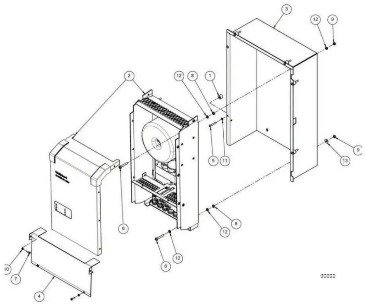
Item Part No. Qty Description Notes
1 A0004899111 1 PRE-ASSEMBLED INVERTER DOOR - WHITE
2 A0004899114 1 PRE-ASSEMBLED COMMAND BOX DOOR - WHITE
3 4 SCREW TSIC M5 X 20 CL 4.8
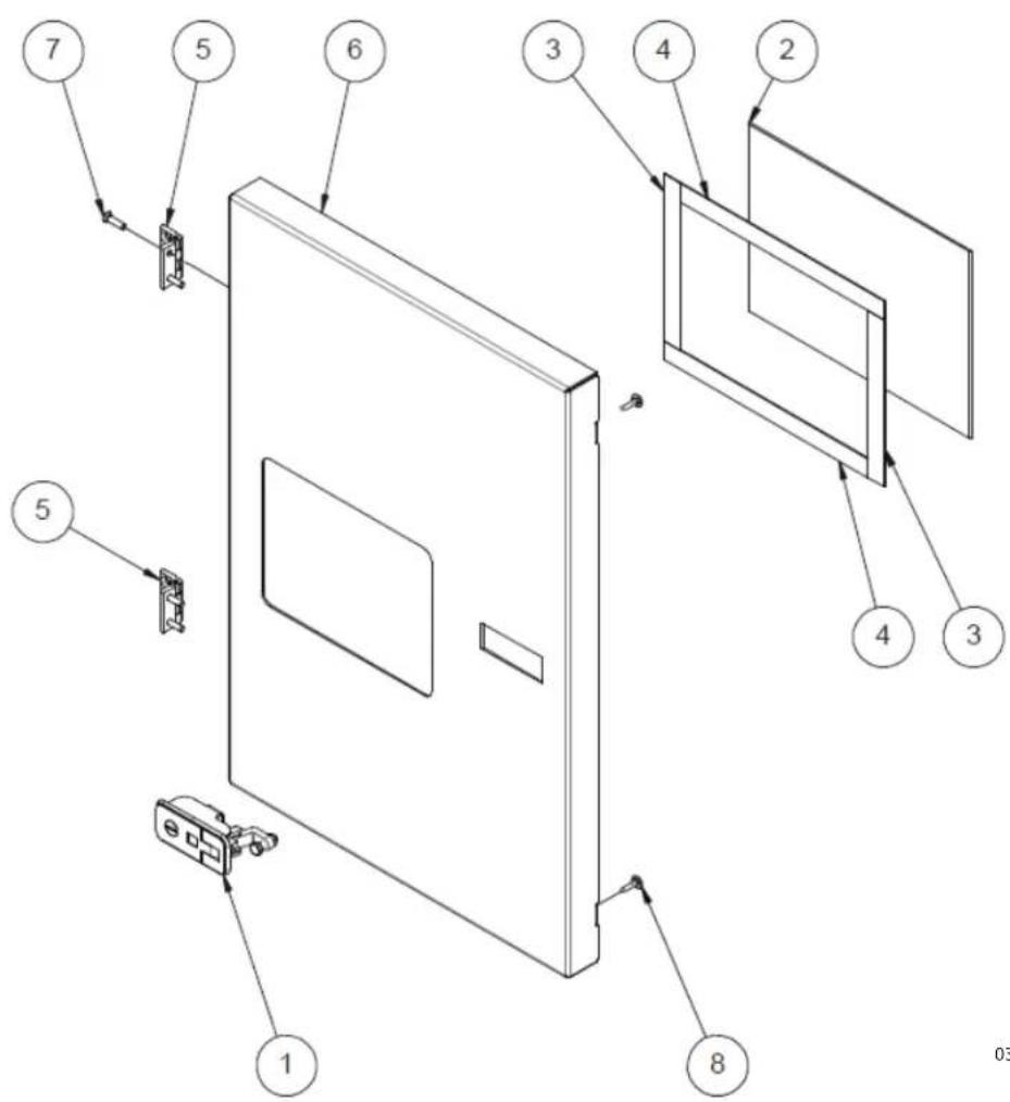
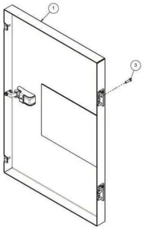
Item Part No. Qty Description Notes
-- A0004899111 PRE-ASSEMBLED INVERTER DOOR - WHITE
1 A0004899115 1 CLOSURE WITH LOCK
2 A0004899117 1 LEXAN PANEL
3 2 VHB ADHESIVE TAPE 4910 L 170 mm
4 2 VHB ADHESIVE TAPE 4910 L 240 mm
5 A0004899182 2 SYMMETRICAL HINGE 40X40
6 A0004899186 1 INVERTER DOOR - WHITE
7 4 SCREW TSIC M5X20 CL 4.8
8 56536 2 DOOR JAMB STOPPER, RUBBER
03980
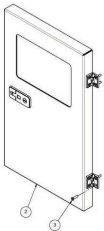
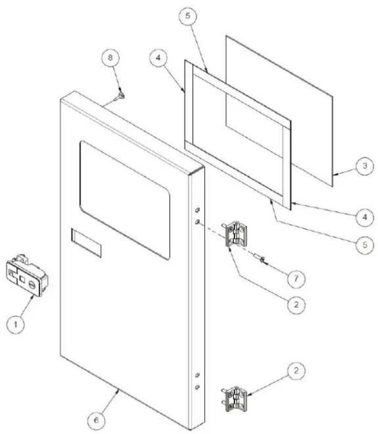
Item Part No. Qty Description Notes
-- A0004899114 1 COMMAND BOX DOOR-PRE-ASSEMBLED
1 A0004899115 1 CLOSURE WITH LOCK
2 A0004899182 2 SYMMETRICAL HINGE 40X40
3 A0004899117 1 LEXAN PANEL
4 2 VHB ADHESIVE TAPE 4910 L 170 mm
5 2 VHB ADHESIVE TAPE 4910 L 240 mm
6 A0004899239 1 COMMAND BOX DOOR - WHITE
7 4 SCREW TSIC M5 X 20 CL 4.8
8 56536 2 DOOR JAMB STOPPER, RUBBER
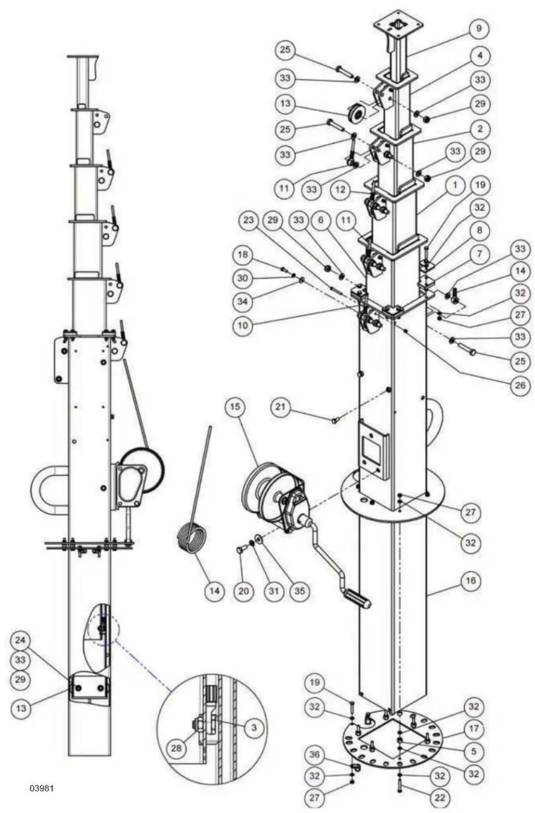
Item Part No. Qty Description Notes
1 A0000764065 1 3° SECTION MAST ASSEMBLED 100 X 100 X 3
2 A0000764066 2 4° SECTION MAST ASSEMBLED 80 X 80 X 3
3 A0004899524 1 M8 SCREW HEAD FOR MAST LIFTING CABLE
4 A0000764102 1 5° SECTION MAST ASSEMBLED 60 X 60 X 3
5 A0004899525 1 HEXAGONAL COLUMN M6
6 A0000763085 1 2° SECTION MAST ASSEMBLED 120 X 120 X 3
7 A0000763088 4 ANGULAR FOR MAST
8 A0004899528 4 NYLON ANGULAR BLOCKING PLATE
9 A0000763544 1 6° SECTION MAST ASSEMBLED 40 X 40 X 4
10 A0000216359 1 COMPLETE GALV. STEEL CABLE D.6 L.1440
11 A0000216360 1 COMPLETE GALV. STEEL CABLE D.6 L.1460
12 A0000216368 1 COMPLETE GALV. STEEL CABLE D.6 L.1455
13 A0000300988 1 D.60 WHEEL FOR STEEL CABLE SPECIFY DIA
14 A0000765854 1 COMPLETE GALV. STEEL CABLE D.6 L.4300 FOR WINCH
15 A0000763370 1 WINCH MANUAL 900 KG
16 A0004899529 1 1° SECTION MAST ASSEMBLED 150 X 150 X 3
17 A0004899530 1 MAST STOP DISK
18 1 SCREW TE M6 X 16 CL 8.8
19 8 SCREW TE M6 X 35 CL 8.8
20 3 SCREW TE M10 X 25 CL 8.8
21 2 SCREW TE M8 X 16 CL 8.8
22 6 SCREW TE M6 X 40 CL 8.8
23 5 SCREW TE (PT) M5 X 40 CL 8.8
24 2 SCREW TE (PT) M10 X 50 CL 8.8
25 2 SCREW TE (PT) M10 X55 CL 8.8
26 5 NUT ATB A M5
27 9 NUT ATB B M6
28 1 NUT ATB B M8
29 2 NUT ATB B M10
30 1 WASHER EL 6,1 X 11, 8 X 1,6
31 3 WASHER EL 10,2 X 18,1 X 2,2
32 30 WASHER PN 6,4 X 12 X 1,6 SS
33 12 WASHER PN 10,5 X 20 X 2 SS
34 1 WASHER PL 6,4 X 18 X 1,6 SS
35 3 WASHER PL 10,5 X 30 X 2,5 SS
36 2 RSGU1 10/15 M6 CLAMP
03982
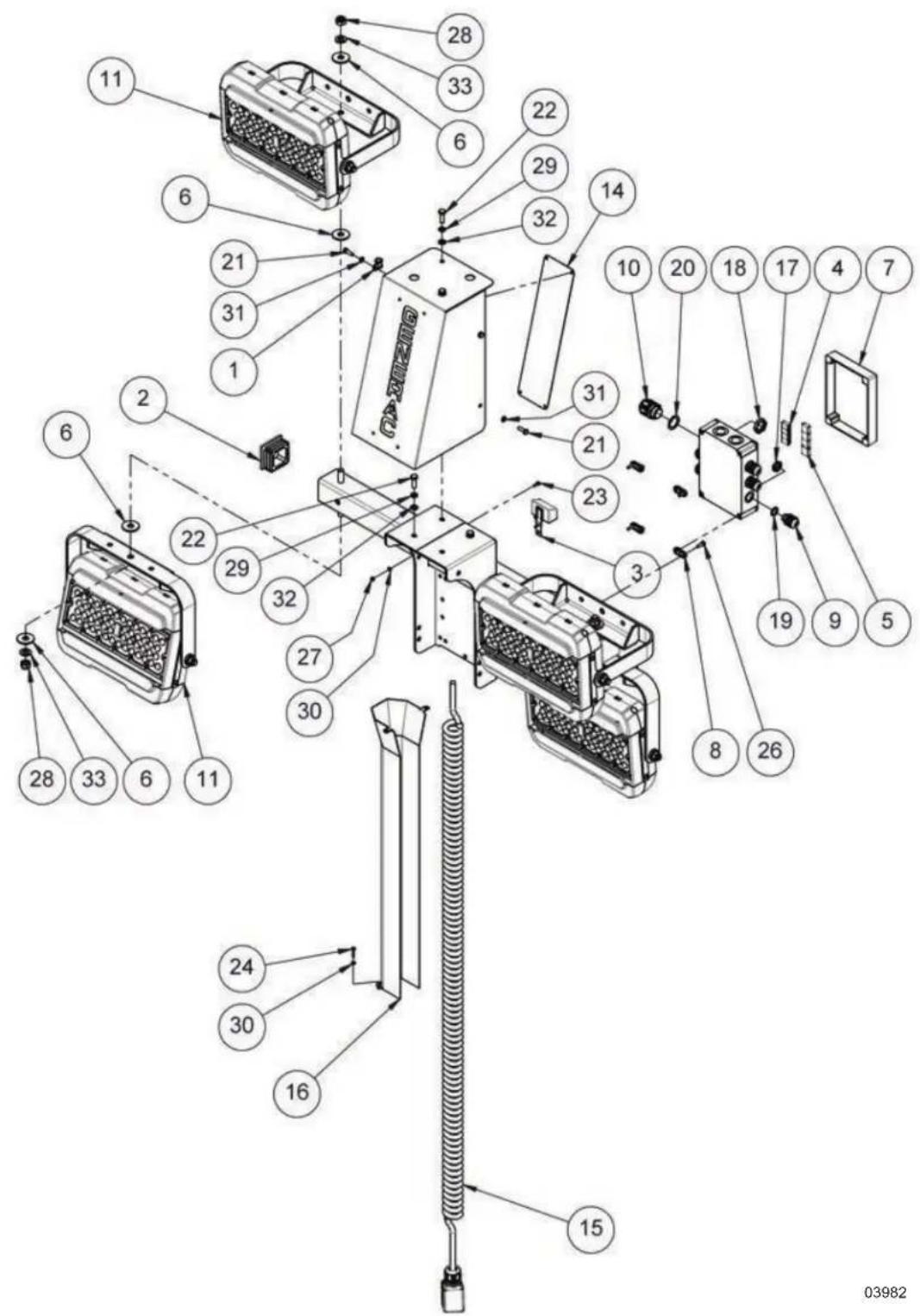
Item Part No. Qty Description Notes
1 1 RSGU1 10/15 M6 CLAMP
2 A0000762115 2 60X60 FINNED COVER
3 A0000216084 1 LIGHT SENSOR
4 A0000763368 4 JUNCTION CONNECTOR 2P
5 A0004899532 4 JUNCTION CONNECTOR 3P
6 A0000763448 8 DI13 DE37 TH.3 PLASTIC WASHER
7 A0004899533 1 JUNCTION BOX UL/CSA 180 X 130 X 75
8 A0004899536 4 BRACKET KIT FOR UL/CSA BOX 180 X 130 X 75
9 A0001079861 5 M16 X 1,5 UL/CSA WIRE HOLDER
10 A0001079866 1 M25 X 1,5 (16MM)(-4°C) WIRE HOLDER
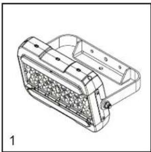
11 A0004899538 4 FLOODLIGHT LED 100W
12 A0004899542 4 FLOODLIGHT SUPPORT - BLACK
13 A0004899545 FLOODLIGHT SUPPORT CLOSING PLATE - BLACK
14 A0004899859 1 BOTTOM SHEET FLOODLIGHT CLOSING PLATE - ORANGE
15 A0004899864 1 7G X1,5MMQ COIL CORD WITH 6P MALE
16 A0004899868 1 COIL CORD GUIDE - BLACK
17 A0001079863 5 M16 COUNTER NUT
18 A0000883280 1 M25 COUNTER NUT
19 A0001079862 5 M16 FLAT GASKET
20 A0001079865 1 M25 FLAT GASKET
21 4 SCREW TE M6 X 20 CL 8.8
22 4 SCREW TE M8 X 25 CL 8.8
23 1 SCREW TCCIC M4 X 12 CL 4.8
24 4 SCREW TCCIC M4 X 20 CL 4.8
25 A0004407516 0 SCREW TCCIC M5 X 20 CL 4.8
26 4 SCREW TCCIC M5 X 16 CL 4.8
27 2 NUT ATB B M4
28 4 NUT ATB B M12
29 4 WASHER EL 8,2 X 14,8 X 2
30 4 WASHER PN 4,3 X 9 X 0,8 SS
31 4 WASHER PN 6,4 X12 X1,6 SS
32 4 WASHER PN 8,4 X16 X1,6
33 8 WASHER PN 13 X 24 X 2,5 SS
03983
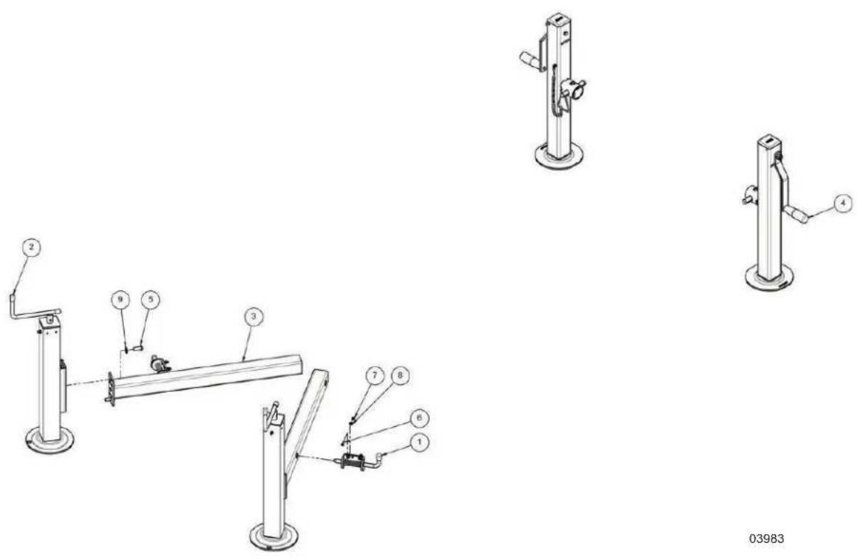
Item Part No. Qty Description Notes
1 56516 2 SPRING BOLT WITHOUT PINS
2 A0004899871 2 STABILIZER
3 A0004899872 2 ASSEMBLED TUBULAR FOR STABILIZER
4 A0004899988 2 ROTATABLE STABILIZER
5 8 SCREW TBEI M10 X 25 CL 4.8
6 4 SCREW TSIC M5 X 20 CL 4.8
7 4 NUT ATB B M5
8 4 WASHER PN 5,3 X 10 X 1 SS
9 8 WASHER PN 10,5 X 20 X 2 SS
03984
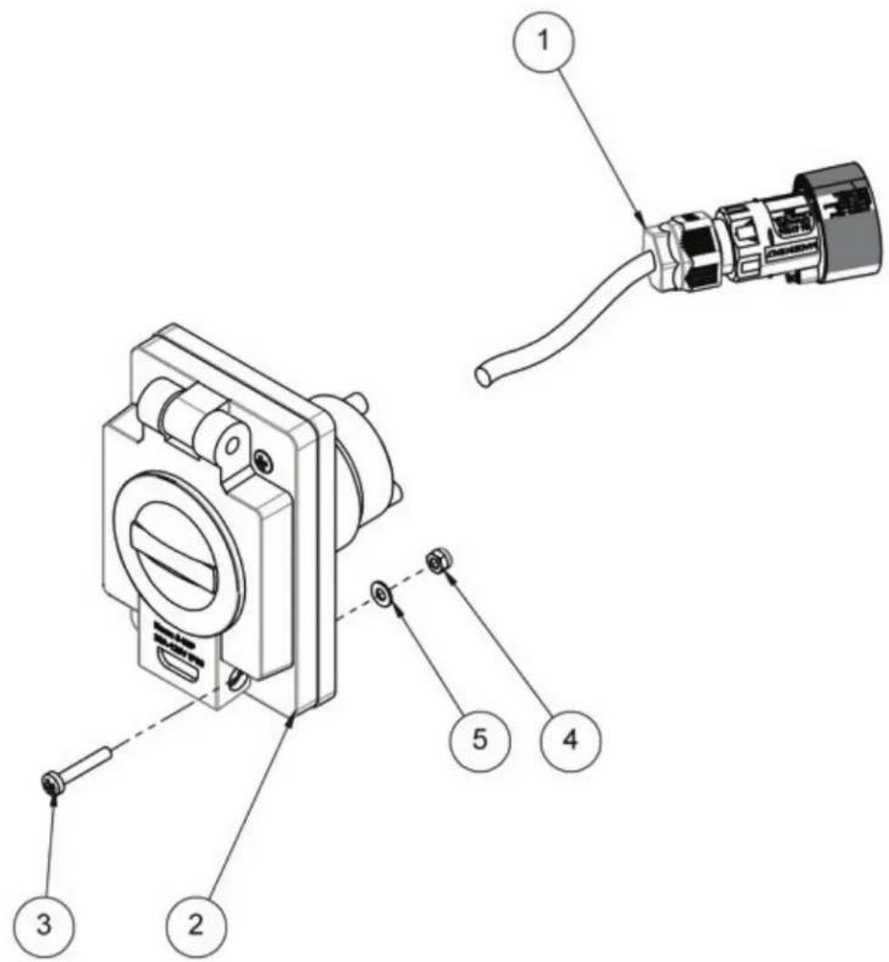
Item Part No. Qty Description Notes
1 A0004899993 1 MAINS INPUT PLUG HARNESS [SOLAR V.1.5 NA]
2 A0004899995 1 RECEPTACLE 120V/20A INLET (5-20P) WITH
COVER - YELLOW
3 4 SCREW TCCIC M4 X 25 CL 4.8
4 4 NUT ATB B M4
5 4 WASHER PN 4,3 X 9 X 0,8
03985
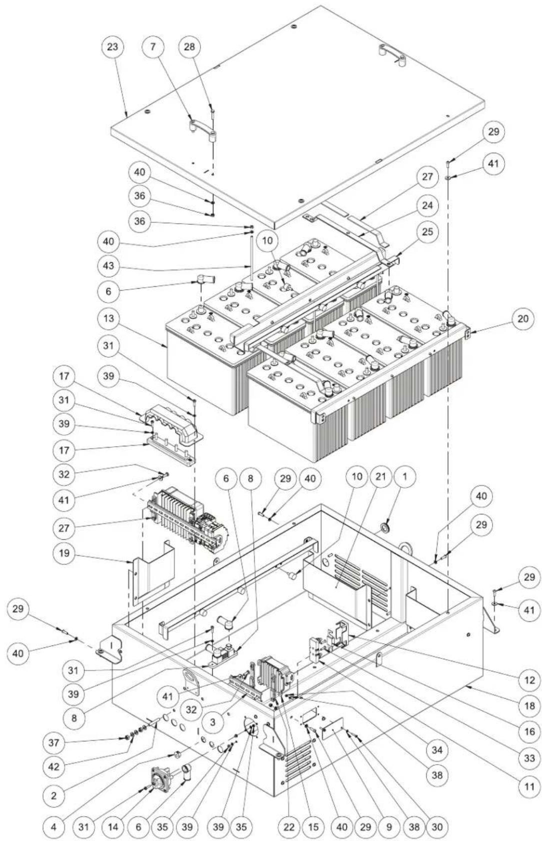
Item Part No. Qty Description Notes
| 1 A0004900000 1 MEMBRANE CABLE GLAND D.21 X 35 | ||
| 2 A0000748380 1 M8 X 50 BRASS THREADED BAR | ||
| 3 A0004900001 1 DIN RAIL TH 35-7,5 L = 150 | ||
| 4 56609 1 PLASTIC CAP D. 20,6 | ||
| 5 11327 1 STOP TERMINAL BOARD | ||
| 6 A0000747931 16 RUBBER CAP PROTECTION FOR BATTERIES | ||
| 7 A0004900034 2 PLASTIC HANDLE CENTER DISTANCE 93 MM (BLUE CAPS) | ||
| 8 A0004900042 1 SHUNT 500A 50MA | ||
| 9 A0004900049 1 CONNECTOR CAP 10P ILME - BLACK | ||
| 10 A0000507211 12 D.20 X15 M6 X16 55SH ANTI-VIBRATION | ||
| 11 A0004900051 1 FUSE HOLDER FOR FT2 FUSE (FP1020) | ||
| 12 A0004900417 1 FUSE HOLDER COVER FOR FT2 (CP1020 | ||
| 13 A0004900433 8 BATTERY EV31A-A AM F10M8 12V 120AH C20 | ||
| 14 A0004915780 1 MAN BATTERY DISCONNECT SWITCH 48V 300A | ||
| 15 A0004915782 1 DC-C CONVERTER ORION-TR 48/12-9A 110W | ||
| 16 A0004915784 1 125A 48V FT2 FUSE | ||
| 17 A0004915785 1 BUS BAR 250A 4P + COVER | ||
| 18 A0004915812 1 ASSEMBLED BATTERY COMPARTMENT - WHITE | ||
| 19 A0004915831 2 LATERAL AIR INTAKE - BLACK | ||
| 20 A0004915861 2 BATTERIES STOP BRACKET - BLACK | ||
| 21 A0004915866 2 INTERNAL PROTECTION FOR REAR AIR INTAKE - BLACK | ||
| 22 A0004915939 2 DIN 35 ADAPTER LARGE | ||
| 23 A0004915972 1 ASSEMBLED BATTERY BOX COVER - W | ||
| 24 A0004916004 2 COPPER JUMPER FOR BATTERY CONNECTION | ||
| 25 A0004916007 1 CENTRAL BATTERIES STOP BRACKET - BLACK | ||
| 26 A0004916033 1 SOLAR PANELS CONNECT KIT WITH MPPT 150/35 | ||
| 27 A0004916035 4 HEAT SHRINK SLEEVE | ||
| 28 4 SCREW TE M6 X 30 CL 8.8 | ||
| 29 19 SCREW TBEI M6 X 20 CL 10.9 | ||
| 30 2 SCREW TCCIC M4 X 20 CL 4.8 | ||
| 31 10 SCREW TCCIC M5 X 20 CL 4.8 | ||
| 32 4 SCREW TCCIC M6 X 20 CL 4.8 | ||
| 33 4 SCREW TSIC M5 X 20 CL 4.8 | ||
| 34 2 NUT ATB B M4 | ||
| 35 4 NUT ATB B M5 | ||
| 36 6 NUT ATB B M6 | ||
| 37 4 NUT N M8 - BRASS | ||
| 38 4 WASHER PN 4,3 X 9 X 0,8 SS | ||
| 39 10 WASHER PN 5,3 X 10 X 1 SS | ||
| 40 19 WASHER PN 6,4 X 12 X 1,6 SS | ||
| 41 10 WASHER PL 6,4 X 18 X 1,6 SS | ||
| 42 6 WASHER PN 8,4 X 16 X 1,6 BRASS | ||
| 43 A0004916040 1 THREADED ROD M6 180 MM |
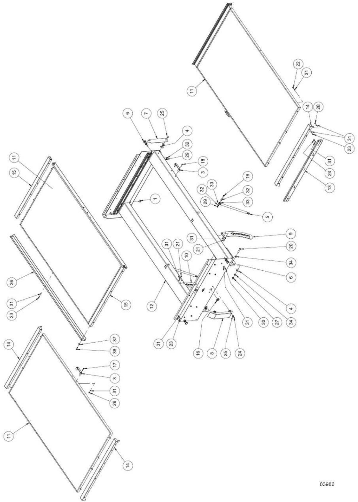
Item Part No. Qty Description Notes
| 1 A0004900000 1 MEMBRANE CABLE GLAND D.21X35 |
| 2 A0002959677 2 D.25 X 10,1 X M6 ANTI-VIBRATION |
| 3 A0004900034 8 PLASTIC HANDLE CENTER DISTANCE 93 MM (BLUE CAPS) |
| 4 A0000763448 2 DI13 DE37 TH.3 PLASTIC WASHER BLACK |
| 5 A0004916049 2 GAS SPRING 1000N |
| 6 A0004916053 4 SPRING PLUNGER |
| 7 A0004916061 2 ANTI-THEFT BRACKET |
| 8 A0004916064 1 REAR COVER - WHITE |
| 9 A0004916065 1 GRADUATED RIGHT ARCH |
| 10 | A0004916066 | 1 | GRADUATED LEFT ARCH |
| 11 | A0004916068 | 3 | SOLAR PANEL 400W MONO 1755 X 1038 X30 |
| 12 | A0004916069 | 1 | ASSEMBLED TILTING CARRIAGE - WHITE |
| 13 | A0004916073 2 HEAVY DUTY FULL - EXTENSION GUIDE | ||
| 14 | A0004916078 | 4 | BRACKET FOR 1750 X 1038 X 30 SOLAR PANEL |
| 15 | A0004916082 | 2 | ADAPTER FOR L-1038 SOLAR PANEL |
| 16 | 12 | SCREW TE M6 X 30 CL 8.8 | |
| 17 | 4 | SCREW TE M6 X 35 CL 8.8 | |
| 18 | 4 | SCREW TE (PT) M8 X 50 CL 8.8 | |
| 19 | 8 | SCREW TCEI M6 X 20 CL 8.8 | |
| 20 | 2 | SCREW TCEI M12 X 50 CL 8.8 | |
| 21 | 24 | SCREW TBEI M6 X 25 CL 8.8 | |
| 22 | 12 | SCREW TBEI M6 X 20 CL 8.8 | |
| 23 | 8 | SCREW TBEI M6 X 16 CL 8.8 | |
| 24 | 2 | SCREW TTQS M8 X 25 CL 4.8 | |
| 25 | 16 | NUT ATB A M6 | |
| 26 | 2 | NUT ATB A M12 | |
| 27 | 12 | NUT ATB B M6 | |
| 28 | 2 | NUT ATB B M8 | |
| 29 | 16 | NUT ECCSA M6 | |
| 30 | 80 | WASHER PN 6,4 X 12 X 1,6 SS | |
| 31 | 8 | WASHER PN 8,4 X 16 X 1,6 SS | |
| 32 | 8 | WASHER PN 10,5 X 20 X 2 SS | |
| 33 | 4 | WASHER PN 13 X 24 X 2,5 SS | |
| 34 | 4 | WASHER PL 6,4 X 18 X 1,6 SS | |
| 35 | A0005459525 | 2 | PHOTO PANEL, LATERAL REINFORCEMENT |
| 36 | 4 | WASHER PL 8,4 X 24 X 2 SS | |
| 37 | 4 | SCREW TBEI M8 X 30 C10.9 | |
Item Part No. Qty Description Notes
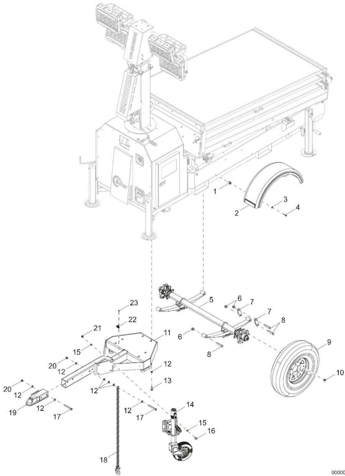
| 1 0J5254 8 BUMPER-HANDLE STOP | |||
| 2 16560 2 FENDER, PLASTIC SHELL - 13 IN TIRE | |||
| 3 0H7899 8 WASHER FLAT M6 X 18MM | |||
| 4 G049721 | 8 SCREW HHC M6-1.0 X 35 C8.8 CLR | ||
| 5 A0004197650 | 1 AXLE SOLAR LIGHT TOWER 3300LBS | ||
| 6 60504 6 NUT, .562-18 LHEX G5 ZC | |||
| 7 19637 4 PLATE, SHACKLE BRACKET - 3.125 | |||
| 8 60503 3 SCREW, SHACKLE, .562-18X3.000 HEX G | |||
| 9 15976 2 WHEEL, ST175/80D13, 1360# - 6PR | |||
| 10 60096 | 10 NUT, .500-20 LUG G5 | ||
| 11 A0004081740 | 1 ST03 WELDMENT HITCH TONGUE | ||
| 12 G049808 | 20 WASHER FLAT M12 | ||
| 13 G052645 | 6 SCREW HHC M12-1.75 X 30 C8.8 | ||
| 14 A0005120232 | 1 JACK WHEEL SIDE WIND 1200LB BRKT MNT | ||
| 15 G070264 | 8 WASHER FLAT M10 | ||
| 16 G049814 | 4 SCREW HHC M10-1.5 X 25 C8. | ||
| 17 G052623 | 4 SCREW HHC M12-1.75 X 100 PC8.8 | ||
| 18 23367 2 CHAIN, SAFETY - 7,800 LBS RATED | |||
| 19 16830 1 COUPLER, 2.00 BALL/2.50 CHANNEL ZP | |||
| 20 0D7119 | 4 NUT HEX LOCK M12-1.75 NY INS | ||
| 21 A0000566363 | 8 NUT HEX LOCK M10-1.5 NY INS | ||
| 22 16143 2 CLAMP, TUBING - .500 | |||
| 23 60268 2 RIVET, .188 DIA X .126 TO .250 GRIP SSB6-4S | |||
00000
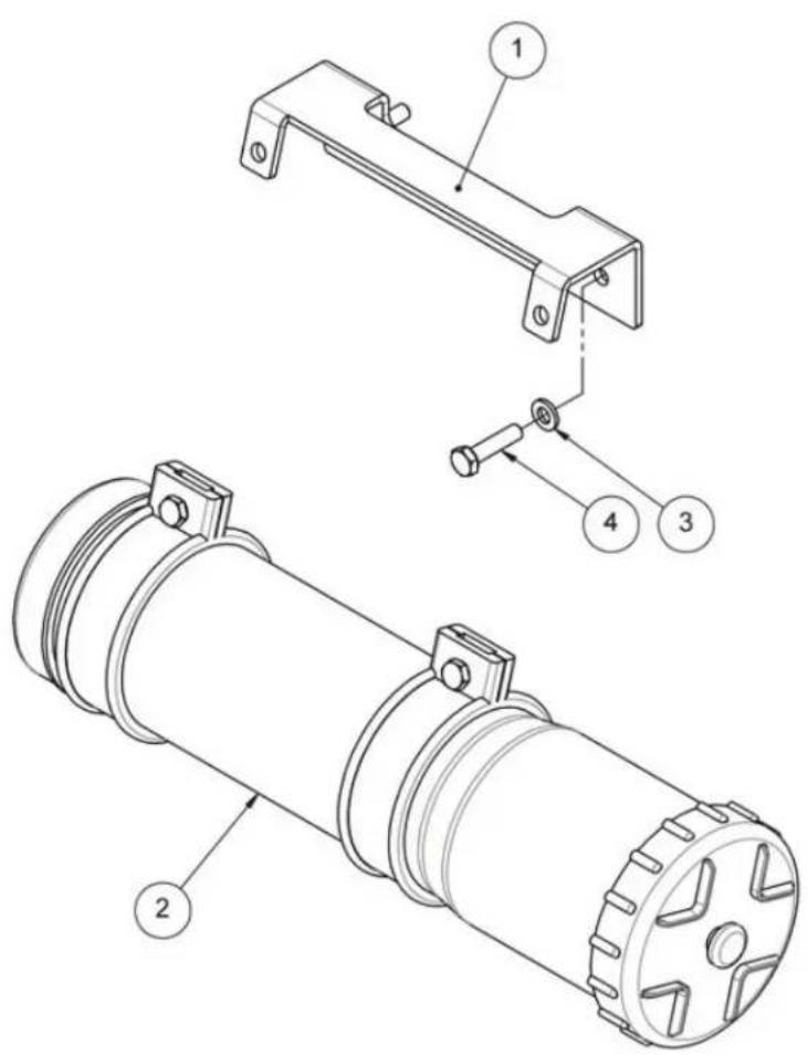
Item Part No. Qty Description Notes
1 A0000763367 1 PLASTIC TUBE DOCUMENT HOLDER
2 A0004916083 1 DOCUMENT HOLDER - BLACK
3 1 WASHER PN 6,4 X 12 X 1,6 SS
4 A0004407524 1 SCREW TE M6 X 25 CL 8.8
Item Part No. Qty Description Notes
| 1 A0004896113 6 PLASTIC SPACER 15 X 5.3 X13 |
| 2 A0004916093 1 INVERTER/CHARGER 48/3000/35-50 120V |
| 3 A0004916097 1 INVERTER BOX120V - BLACK |
| 4 A0004916104 1 120V INVERTER COVER - BLACK |
| 5 | 6 SCREW TBEI M5 X 35 CL 10.9 |
| 6 | 4 SCREW TCCIC M6 X 40 CL 4.8 |
| 7 | 4 SCREW TCCIC M4 X 16 CL 4.8 |
| 8 | 12 NUT N M6 |
| 9 | 4 NUT ATB B M6 |
| 10 | 4 WASHER PN 4,3 X 9 X 0,8 SS |
| 11 | 6 WASHER PN 5,3 X 10 X 1 SS |
| 12 | 8 WASHER PN 6,4 X 12 X 1,6 SS |
| 13 | 4 WASHER PL 6,4 X 18 X 1,6 SS |
natural_image
Technical line drawing of a mechanical component with no visible text or symbols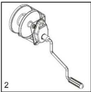
natural_image
Technical line drawing of a mechanical device with a lever and handle (no text or symbols)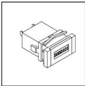
natural_image
Isometric line drawing of a mechanical component with no visible text or symbols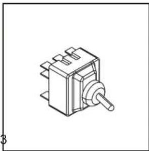
natural_image
Isometric line drawing of a mechanical switch or relay component (no text or symbols)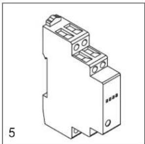
natural_image
Technical line drawing of an electrical component with mounting holes and a base plate (no text or symbols)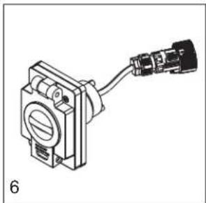
natural_image
Technical line drawing of a mechanical component with a cable and connector (no text or symbols)
natural_image
Isometric line drawing of a rectangular battery or solar cell with cooling fins and terminals (no text or symbols)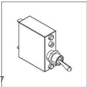
natural_image
Technical line drawing of a mechanical switch or lever assembly (no text or symbols)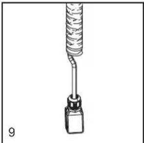
natural_image
Illustration of a mechanical tool with a coiled spring and connector (no text or symbols)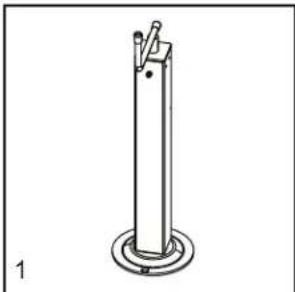
natural_image
Simple line drawing of a vertical cylindrical object with a base, no text or symbols present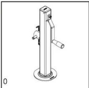
natural_image
Technical line drawing of a vertical cylindrical device with two handles and a base, labeled '0' at the bottom left (no text or symbols on the device itself)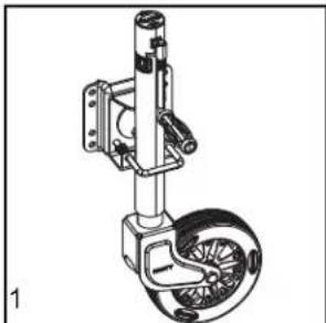
natural_image
Technical line drawing of a mechanical device with a wheel and mounting bracket (no text or symbols)MAST
- FLOODLIGHT LED 100W A0004899538
2 WINCH MANUAL 900 KG A0000763370 - 110V 60HZ HOUR METER WITH 48X24 ADAPTER ...... A0004947355
- ROTARY POTENTIOMETER A0004898529
- 12V DC 1 MOD TWILIGHT RELAY ...... A0004896106
- DRIVER LED 90-305VAC 320W 48V ...... A0004897252
- CIRCUIT BREAKER 20A RATED.... A0004897190
- 7G X1,5MMQ COIL CORD WITH 6P MALE ......A0004899864
- JACK, SIDEWINDER ......A0004899871
- JACK, TOP WIND......A0004899988
- JACK WHEEL SIDE WIND 1200LB BRKT MNT ...... A0005120232
This Page Intentionally Left Blank

Part No. A0004974416 Rev. B 01/23/2024
©2024 Generac Power Systems, Inc.
All rights reserved
Specifications are subject to change without notice.
No reproduction allowed in any form without prior written consent
from Generac Power Systems, Inc.

MOBILE
Generac Power Systems, Inc.
S45 W29290 Hwy. 59, Waukesha WI 53189
GeneracMobileProducts.com | 844-ASK-GNRC | 844-275-4672

Brand : Generac
Model : VT-Solar v.1.5
Category : Lighting