Derby X - Effect machine Chauvet - Free user manual and instructions
Find the device manual for free Derby X Chauvet in PDF.

| Product Type | LED Derby Effect Machine |
| Brand | Chauvet |
| Model | Derby X |
| Dimensions (L x W x H) | 302 x 382 x 187 mm |
| Weight | 1.8 kg |
| Power Supply | AC 100-240 V, 50/60 Hz |
| Power Consumption | 24 W max |
| Fuse | 2 A, 250 V |
| Light Source | 90 LEDs (30 red, 30 green, 30 blue) |
| LED Life Span | 100,000 hours |
| Coverage Angle | 96° |
| DMX Channels | 8 |
| Control Protocol | DMX-512 USITT |
| Operating Modes | Standalone (Sound-Active), Master/Slave, DMX |
| Special Functions | Strobe, automatic programs, individual LED control |
| Mounting | Adjustable orientation, hanging with clamp (sold separately), stacking up to 4 units |
| Max Ambient Temperature | 40 °C |
| Maintenance | Regular cleaning with vacuum and soft cloth |
| Available Spare Parts | LED board (P222-DERBYX), power supply (P140-DERBYX), main board (P172-DERBYX) |
| Warranty | Limited 2 years |
| Package Contents | 1 x Derby X, power cord, warranty card, user manual |
Frequently Asked Questions - Derby X Chauvet
User questions about Derby X Chauvet
0 question about this device. Answer the ones you know or ask your own.
Ask a new question about this device
Download the instructions for your Effect machine in PDF format for free! Find your manual Derby X - Chauvet and take your electronic device back in hand. On this page are published all the documents necessary for the use of your device. Derby X by Chauvet.
USER MANUAL Derby X Chauvet
| OK on Dimmer | |
| Outdoor OK | |
| Sound-Activated | √ |
| DMX512 | √ |
| Master/Slave | √ |
| Autoswitching Transformer | √ |
| Replaceable Fuse | √ |
| User Serviceable |
USER MANUAL
natural_image
Technical line drawing of a robotic vehicle with a triangular pointer overlay (no text or symbols)
5200 NW 108th Avenue, Sunrise, FL 33351 U.S.A.
(800) 762-1084-(954) 929-1115
FAX (954) 929-5560
www.chauvetlighting.com
TABLE OF CONTENTS
1. Before You Begin.... 5
WHAT IS INCLUDED ....5
UNPACKING INSTRUCTIONS 5
AC POWER....5
SAFETY NOTES....6
2. Introduction......7
FEATURES....7
DMX CHANNEL SUMMARY 7
PRODUCT OVERVIEW....7
3. Setup 8
FUSE REPLACEMENT 8
PRODUCT LINKING....8
Master/Slave Product Linking....8
MOUNTING....9
Orientation 9
Rigging 9
STACKING....10
4. Operating Instructions....11
Standalone Mode (Sound-Active): 11
Master/Slave Mode (Master Sound): 11
DMX Mode....11
DMX CHANNEL VALUES 12
Setting the Starting Address.... 13
DMX Quick Reference Chart....14
TROUBLESHOOTING GUIDE 15
5. Appendix....16
GENERAL MAINTENANCE 16
RETURNS PROCEDURE 16
CLAIMS 16
TECHNICAL SPECIFICATIONS 17
2. Introduction....34
CARACTERISTIQUES 34
RESUME DES CANAUX DMX 34
3. Installation....35
REMPLACEMENT DU FUSIBLE 35
RACCORDEMENT DE L'APPAREIL 35
KOPPELING VAN PRODUCTEN....61
GIDS VOOR PROBLEEMOPLOSSING 68
- Bijlage 69
ALGEMEEN ONDERHOUD 69
RETOURPROCEDURE 70
CLAIMS 70
Unpacking Instructions
Immediately upon receiving a product, carefully unpack the carton, check the contents to ensure that all parts are present, and have been received in good condition. Notify the shipper immediately and retain packing material for inspection if any parts appear damaged from shipping or the carton itself shows signs of mishandling. Save the carton and all packing materials. In the event that a product must be returned to the factory, it is important that the product be returned in the original factory box and packing.
AC Power
This product has an auto-switching power supply. This product will accommodate between 100 VAC and 240 VAC 50/60 Hz. All products must be powered directly off a switched circuit and cannot be run off a rheostat (variable resistor) or dimmer circuit, even if the rheostat or dimmer channel is used solely for a 0 to 100% switch.

To eliminate wear and improve its lifespan, during periods of non-use completely disconnect from power via breaker or by unplugging it.
Safety Notes
Please read these instructions carefully, which includes important information about the installation, usage and maintenance of this product.
- Please keep this User Manual for future consultation. If you sell the product to another user, be sure that they also receive this instruction booklet.
- Always make sure that you are connecting to the proper voltage, and that the line voltage you are connecting to is not higher than that stated on the decal or rear panel of the product.
- This product is intended for indoor use only! To prevent risk of fire or shock, do not expose product to rain or moisture. Make sure there are no flammable materials close to the product while operating.
- The product must be installed in a location with adequate ventilation, at least 20in (50cm) from adjacent surfaces. Be sure that no ventilation slots are blocked.
- Always disconnect from power source before servicing or replacing lamp or fuse and be sure to replace with same lamp source.
- Secure product to fastening device using a safety chain.
• Never carry the product solely by its head. Use its carrying handles. - Maximum ambient temperature (Ta) is 104 °F (40 °C). Do not operate product at temperatures higher than this.
- In the event of a serious operating problem, stop using the product immediately. Never try to repair the product by yourself. Repairs carried out by unskilled people can lead to damage or malfunction. Please contact the nearest authorized technical assistance center. Always use the same type spare parts.
• Never connect the device to a dimmer pack or rheostat.
• Make sure the power cord is never crimped or damaged. - Never disconnect the power cord by pulling or tugging on the cord.
- Avoid direct eye exposure to the light source while it is on.
- To eliminate wear and improve its lifespan, during periods of non-use completely disconnect from power via breaker or by unplugging it.
Caution!
There are no-user serviceable parts inside the product. Do not open the housing or attempt any repairs yourself. In the unlikely event your product may require service, please contact Chauvet Technical Support.
2. INTRODUCTION
Features
• 8-channel DMX-512 LED derby effect
- Blackout/static/strobe
- Individual control of red, green, and blue LEDs within each cluster (6 total)
• Built-in automated programs via DMX
• Built-in sound activated programs via master/slave or DMX
- Mount multiple products together with adjustable, optional bracket (XBRACKET)
• Additional power output: max 27 products @ 120V (see manual for details)
DMX Channel Summary
| Channel | Description |
| 1 | LED Cluster 1 |
| 2 | LED Cluster 2 |
| 3 | LED Cluster 3 |
| 4 | LED Cluster 4 |
| 5 | LED Cluster 5 |
| 6 | LED Cluster 6 |
| 7 | Strobe |
| 8 | Auto Programs |
Product Overview
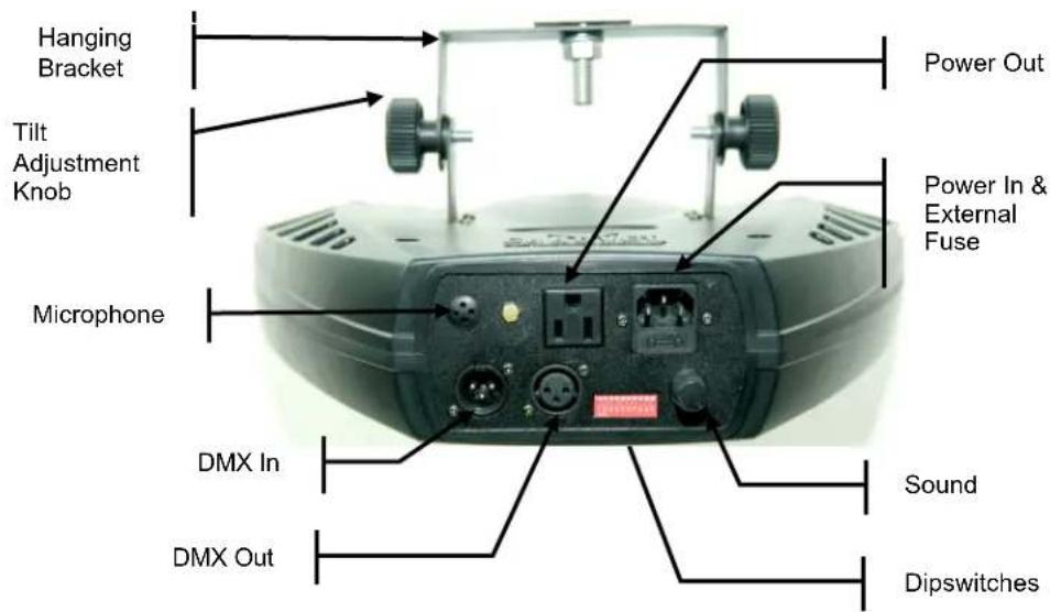
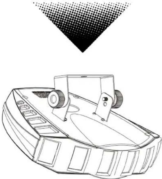
text_image
Hanging Bracket Tilt Adjustment Knob Microphone Power Out Power In & External Fuse DMX In Sound DMX Out Dipswitches3. SETUP
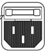
Fuse Replacement

Disconnect the power cord before replacing a fuse and always replace with the same type fuse.

With a flat-head screwdriver wedge the fuse holder out of its housing. Remove the
damaged fuse from its holder and replace with exact same type fuse. Insert the fuse holder back in its place and reconnect power.
The fuse is located inside this compartment. Remove using a flat head screwdriver.
Product Linking
You will need a serial data link to run light shows of one or more products using a DMX-512 controller or to run synchronized shows on two or more products set to a master/slave operating mode. The combined number of channels required by all the products on a serial data link determines the number of products the data link can support.
Important: Products on a serial data link must be daisy chained in one single line. To comply with the EIA-485 standard no more than 32 devices should be connected on one data link. Connecting more than 32 products on one serial data link without the use of a DMX optically-isolated splitter may result in deterioration of the digital DMX signal.
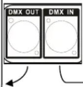
Master/Slave Product Linking
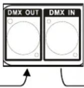
- Connect the (male) 3 pin connector side of the DMX cable to the output (female) 3 pin connector of the first product.
- Connect the end of the cable coming from the first product which will have a (female) 3 pin connector to the input connector of the next product consisting of a (male) 3 pin connector. Then, proceed to connect from the output as stated above to the input of the following product and so on.
Often, the setup for Master-Slave and Standalone operation requires that the first product in the chain be initialized for this purpose via either settings in the control panel or DIP-switches. Secondarily, the products that follow may also require a slave setting. Please consult the "Operating Instructions" section in this manual for complete instructions for this type of setup and configuration.
Slave
Slave
Master
Mounting
Orientation
This product may be mounted in any safe position provided there is adequate room for ventilation.
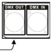
Rigging
It is important never to obstruct the fan or vents pathway. Mount the product using, a suitable "C" or "O" type clamp. Adjust the angle of the product by loosening both knobs and tilting the product. After finding the desired position, retighten both knobs.
- When selecting installation location, take into consideration lamp replacement access and routine maintenance.
• Safety cables must always be used. - Never mount in places where the product will be exposed to rain, high humidity, extreme temperature changes or restricted ventilation.
text_image
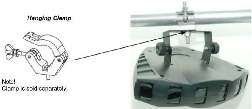
Hanging Clamp Note! Clamp is sold separately.Stacking
The Derby X ^TM may be “stacked” by using multiple products and the optional bracket (XBRACKET). This bracket may be ordered from Chauvet.
The bracket kit will ship with 2pcs bracket (as shown below) and will include 4 screws for attaching it to the bottom of the product.
Note: When you are installing this bracket, you must use the washers and bracket tightening knob to secure one product to another.
Note: A maximum of 4 products can be stacked.
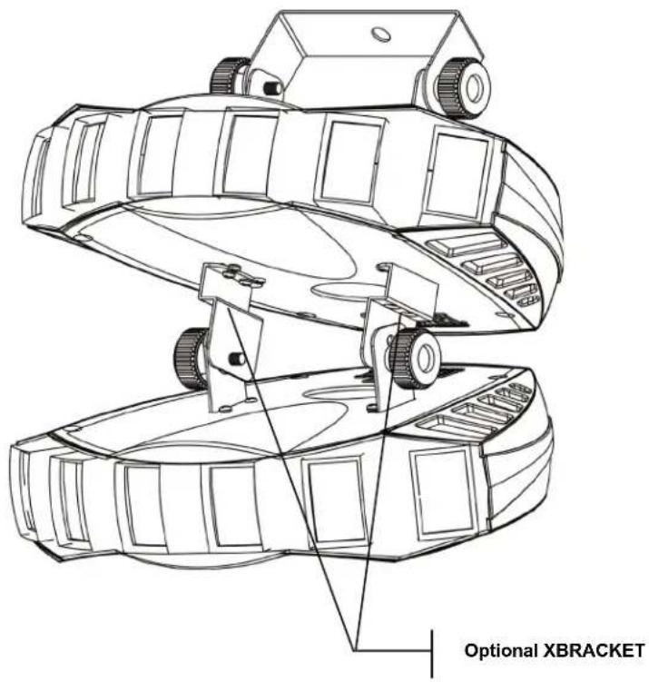
text_image
Optional XBRACKET4. OPERATING INSTRUCTIONS
Standalone Mode (Sound-Active):
This mode allows a single product to run to the beat of the music, or the product will auto change in Auto Mode.
1) Set all dipswitches position to the Off position.
Mode Dipswitches
Sound Active 10 = Off
2) The product will react to the low frequencies of music via the internal microphone in Sound-Active mode.
3) Use the audio sensitivity knob on the back of the product to make the product more or less sensitive in Sound-Active mode. Turning the knob counterclockwise decreases the sensitivity; turning the knob clockwise increases the sensitivity.
Master/Slave Mode (Master Sound):
This mode will allow you to link up to 32 products together without a controller.
1) Use standard DMX cables to daisy chain your products together via the DMX connector on the rear of the products. For longer cable runs we suggest a terminator at the last product.
2) Choose a product to function as the Master. Turn dipswitches to the Master position on the product. The product must be the first product in line. Then simply chain the products together using DMX cable.
Mode Dipswitches
Master Sound 10 = Off
3) Turn switch to the Slave position on the slave products, and they will react the same as the Master.
Mode Dipswitches
Slave 1 = On, 10 = On
DMX Mode
If you are unfamiliar with DMX, download the DMX Primer from the www.chauvetlighting.com website.
1) Set the dipswitches to DMX mode.
Mode Dipswitches
DMX 10 = On
2) Connect a DMX controller to the product.
3) Set the start address according to standard binary code.
DMX Channel Values
| Channel | Value | Function |
| 1 | Cluster Control | |
| 2 | 000 ⇔ 010 | No function |
| 011 ⇔ 045 | Red | |
| 3 | 046 ⇔ 080 | Green |
| 081 ⇔ 115 | Blue | |
| 4 | 116 ⇔ 150 | Red/Green |
| 5 | 151 ⇔ 185 | Red/Blue |
| 186 ⇔ 220 | Green/Blue | |
| 6 | 221 ⇔ 255 | Red/Green/Blue |
| 7 | Strobe | |
| 000 ⇔ 010 | No function | |
| 011 ⇔ 255 | Strobe 0%~100% | |
| 8 | Auto Speed | |
| 000 ⇔ 010 | No function | |
| 011 ⇔ 024 | Auto 1 | |
| 025 ⇔ 038 | Auto 2 | |
| 039 ⇔ 052 | Auto 3 | |
| 053 ⇔ 066 | Auto 4 | |
| 067 ⇔ 080 | Auto 5 | |
| 081 ⇔ 094 | Auto 6 | |
| 095 ⇔ 108 | Auto 7 | |
| 109 ⇔ 122 | Auto 8 | |
| 123 ⇔ 136 | Auto 9 | |
| 137 ⇔ 150 | Auto 10 | |
| 151 ⇔ 164 | Auto 11 | |
| 165 ⇔ 178 | Auto 12 | |
| 179 ⇔ 192 | Auto 13 | |
| 193 ⇔ 206 | Auto 14 | |
| 207 ⇔ 220 | Auto 15 | |
| 221 ⇔ 250 | Auto 16 | |
| 251 ⇔ 255 | Audio trigger |
Setting the Starting Address
Set the start address using the group of DIP switches located usually on bottom of the product. Each dip switch has an associated value. Adding the value of each switch in the ON position will provide the start address. Figuring out which switches to toggle ON given a specific start address can be accomplished by determining which switch values will add up to the address value and turning these switches on. Do so by doing the following:
1) Determine the largest value switch that is less than the start address. Turn this switch on.
2) Subtract the value of the switch you just turned on from the starting address number.
3) Determine the largest value switch that is less than the remainder from the previous subtraction. Turn this switch on.
4) Subtract the value of the switch you just turned on from the remainder of the previous subtraction.
5) Repeat steps three and four until you have a remainder of zero.
Example Starting Address
| Address 10Switch # 4 = 8Switch # 2 = 2Total = 10 | 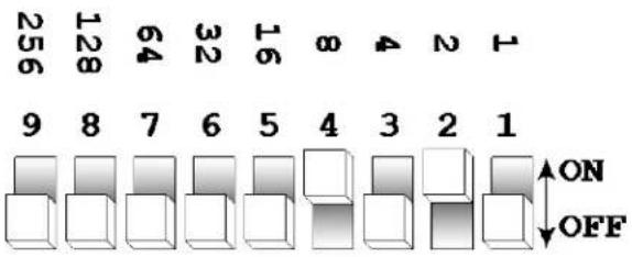 | |
| Address 24Switch # 5 = 16Switch # 4 = 8Total = 24 | 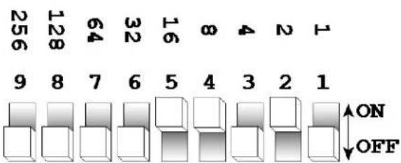 | |
| Resolving addressusing simple math.Address 233 | 233 – (128) = 105, Turn ON Dip # 8105 – (64) = 41, Turn ON Dip # 741 – (32) = 9, Turn ON Dip # 69 – (8) = 1, Turn ON Dip # 41 – (1) = 0, Turn ON Dip # 1 | DIPSWITCH(DMX VALUE) |
| 112234851663276481289256 | ||
DMX Quick Reference Chart
DMX Address Quick Reference Chart
Dip Switch Position
| DMX DIP SWITCH SET0=OFF1=ONX=OFF or ON | #9 | 0 | 0 0 | 0 | 0 0 | 0 0 | 1 1 | 1 1 | 1 1 | 1 1 | |||||||||||
| #8 | 0 | 0 | 0 | 0 | 1 | 1 | 1 | 1 | 0 | 0 | 0 | 0 | 1 | 1 | 1 | 1 | |||||
| #7 | 0 | 0 | 1 | 1 | 0 | 0 | 1 | 1 | 0 | 0 | 1 | 1 | 0 | 0 | 1 | 1 | |||||
| #6 | 0 | 1 | 0 | 1 | 0 | 1 | 0 | 1 | 0 | 1 | 0 | 1 | 0 | 1 | 0 | 1 | |||||
| #1 | #2 | #3 | #4 | #5 | |||||||||||||||||
| 0 | 0 | 0 | 0 | 0 | 32 | 64 | 96 | 128 | 160 | 192 | 224 | 256 | 288 | 320 | 352 | 384 | 416 | 448 | 480 | ||
| 1 | 0 | 0 | 0 | 0 | 1 | 33 | 65 | 97 | 129 | 161 | 193 | 225 | 257 | 289 | 321 | 353 | 385 | 417 | 449 | 481 | |
| 0 | 1 | 0 | 0 | 0 | 2 | 34 | 66 | 98 | 130 | 162 | 194 | 226 | 258 | 290 | 322 | 354 | 386 | 418 | 450 | 482 | |
| 1 | 1 | 0 | 0 | 0 | 3 | 35 | 67 | 99 | 131 | 163 | 195 | 227 | 259 | 291 | 323 | 355 | 387 | 419 | 451 | 483 | |
| 0 | 0 | 1 | 0 | 0 | 4 | 36 | 68 | 100 | 132 | 164 | 196 | 228 | 260 | 292 | 324 | 356 | 388 | 420 | 452 | 484 | |
| 1 | 0 | 1 | 0 | 0 | 5 | 37 | 69 | 101 | 133 | 165 | 197 | 229 | 261 | 293 | 325 | 357 | 389 | 421 | 453 | 485 | |
| 0 | 1 | 1 | 0 | 0 | 6 | 38 | 70 | 102 | 134 | 166 | 198 | 230 | 262 | 294 | 326 | 358 | 390 | 422 | 454 | 486 | |
| 1 | 1 | 1 | 0 | 0 | 7 | 39 | 71 | 103 | 135 | 167 | 199 | 231 | 263 | 295 | 327 | 359 | 391 | 423 | 455 | 487 | |
| 0 | 0 | 0 | 1 | 0 | 8 | 40 | 72 | 104 | 136 | 168 | 200 | 232 | 264 | 296 | 328 | 360 | 392 | 424 | 456 | 488 | |
| 1 | 0 | 0 | 1 | 0 | 9 | 41 | 73 | 105 | 137 | 169 | 201 | 233 | 265 | 297 | 329 | 361 | 393 | 425 | 457 | 489 | |
| 0 | 1 | 0 | 1 | 0 | 10 | 42 | 74 | 106 | 138 | 170 | 202 | 234 | 266 | 298 | 330 | 362 | 394 | 426 | 458 | 490 | |
| 1 | 1 | 0 | 1 | 0 | 11 | 43 | 75 | 107 | 139 | 171 | 203 | 235 | 267 | 299 | 331 | 363 | 395 | 427 | 459 | 491 | |
| 0 | 0 | 1 | 1 | 0 | 12 | 44 | 76 | 108 | 140 | 172 | 204 | 236 | 268 | 300 | 332 | 364 | 396 | 428 | 460 | 492 | |
| 1 | 0 | 1 | 1 | 0 | 13 | 45 | 77 | 109 | 141 | 173 | 205 | 237 | 269 | 301 | 333 | 365 | 397 | 429 | 461 | 493 | |
| 0 | 1 | 1 | 1 | 0 | 14 | 46 | 78 | 110 | 142 | 174 | 206 | 238 | 270 | 302 | 334 | 366 | 398 | 430 | 462 | 494 | |
| 1 | 1 | 1 | 1 | 0 | 15 | 47 | 79 | 111 | 143 | 175 | 207 | 239 | 271 | 303 | 335 | 367 | 399 | 431 | 463 | 495 | |
| 0 | 0 | 0 | 0 | 1 | 16 | 48 | 80 | 112 | 144 | 176 | 208 | 240 | 272 | 304 | 336 | 368 | 400 | 432 | 464 | 496 | |
| 1 | 0 | 0 | 0 | 1 | 17 | 49 | 81 | 113 | 145 | 177 | 209 | 241 | 273 | 305 | 337 | 369 | 401 | 433 | 465 | 497 | |
| 0 | 1 | 0 | 0 | 1 | 18 | 50 | 82 | 114 | 146 | 178 | 210 | 242 | 274 | 306 | 338 | 370 | 402 | 434 | 466 | 498 | |
| 1 | 1 | 0 | 0 | 1 | 19 | 51 | 83 | 115 | 147 | 179 | 211 | 243 | 275 | 307 | 339 | 371 | 403 | 435 | 467 | 499 | |
| 0 | 0 | 1 | 0 | 1 | 20 | 52 | 84 | 116 | 148 | 180 | 212 | 244 | 276 | 308 | 340 | 372 | 404 | 436 | 468 | 500 | |
| 1 | 0 | 1 | 0 | 1 | 21 | 53 | 85 | 117 | 149 | 181 | 213 | 245 | 277 | 309 | 341 | 373 | 405 | 437 | 469 | 501 | |
| 0 | 1 | 1 | 0 | 1 | 22 | 54 | 86 | 118 | 150 | 182 | 214 | 246 | 278 | 310 | 342 | 374 | 406 | 438 | 470 | 502 | |
| 1 | 1 | 1 | 0 | 1 | 23 | 55 | 87 | 119 | 151 | 183 | 215 | 247 | 279 | 311 | 343 | 375 | 407 | 439 | 471 | 503 | |
| 0 | 0 | 0 | 1 | 1 | 24 | 56 | 88 | 120 | 152 | 184 | 216 | 248 | 280 | 312 | 344 | 376 | 408 | 440 | 472 | 504 | |
| 1 | 0 | 0 | 1 | 1 | 25 | 57 | 89 | 121 | 153 | 185 | 217 | 249 | 281 | 313 | 345 | 377 | 409 | 441 | 473 | 505 | |
| 0 | 1 | 0 | 1 | 1 | 26 | 58 | 90 | 122 | 154 | 186 | 218 | 250 | 282 | 314 | 346 | 378 | 410 | 442 | 474 | 506 | |
| 1 | 1 | 0 | 1 | 1 | 27 | 59 | 91 | 123 | 155 | 187 | 219 | 251 | 283 | 315 | 347 | 379 | 411 | 443 | 475 | 507 | |
| 0 | 0 | 1 | 1 | 1 | 28 | 60 | 92 | 124 | 156 | 188 | 220 | 252 | 284 | 316 | 348 | 380 | 412 | 444 | 476 | 508 | |
| 1 | 0 | 1 | 1 | 1 | 29 | 61 | 93 | 125 | 157 | 189 | 221 | 253 | 285 | 317 | 349 | 381 | 413 | 445 | 477 | 509 | |
| 0 | 1 | 1 | 1 | 1 | 30 | 62 | 94 | 126 | 158 | 190 | 222 | 254 | 286 | 318 | 350 | 382 | 414 | 446 | 478 | 510 | |
| 1 | 1 | 1 | 1 | 1 | 31 | 63 | 95 | 127 | 159 | 191 | 223 | 255 | 287 | 319 | 351 | 383 | 415 | 447 | 479 | 511 | |
Dip Switch Position
DMX Address
Troubleshooting Guide
| Problem Possible Solution | |
| 1 or more LED's are not illuminating | Clean the product regularly to avoid any such failure. This product is convection cooled, which means that if the surface is kept clean and free of debris, then proper cooling will be allowed to occur |
| An LED may have failed, resulting in an open circuit. In this event, all of the red, green, or blue in a single module will no longer illuminate. This does not mean that all of the LEDs have failed, but the circuit is wired in series. | |
| An LED may have failed, resulting in a short circuit. In this event, only the single LED which has failed will no longer function. This does not mean that all of the LEDs have failed, but the circuit is wired in series. | |
| Note: In the event of LED failure, a replacement LED PCB assembly may be purchased directly from Chauvet Part#: P222-DERBYX | |
| 1 or more LED's are producing very low output | Check that the lens assembly is installed properly. If the lens assembly is not aligned properly over the LEDs, then they will not project fully -See section on Lens Assembly Installation |
| Note: In the event of LED failure, a replacement LED PCB assembly may be purchased directly from Chauvet Part#: P222-DERBYX | |
| Breaker/Fuse keeps blowing | Check total load placed on the electrical circuit |
| Check for a short in the electrical wiring: internal and/or external | |
| Device has no power | Check device's fuse (internal) |
| Check for power on Mains | |
| Note: In the event of auto-switching transformer failure, the product can be sent in for repair; however, a replacement part can be ordered directly from Chauvet Part#: P140-DERBYX | |
| Product is not responding to DMX | Check Control Panel settings for correct addressing |
| Check DMX cables | |
| Check polarity switch settings on the controller | |
| Check cable connections | |
| Call service technician | |
| See page #10 for proper settings to operate in DMX mode | |
| Note: In the event of Master PCB failure, a replacement PCB can be ordered directly from Chauvet Part#: P172-DERBYX | |
| Loss of signal | Use only DMX cables |
| Install terminator | |
| Note: Keep DMX cables separated from power cables or black lights | |
| Standalone operation problem | See page #8 & #10 for details on proper settings and connections |
If you still have a problem after trying the above solutions, please contact Chauvet Technical Support at the location on the next page.
5. APPENDIX
General Maintenance
To maintain optimum performance and minimize wear products should be cleaned frequently. Usage and environment are contributing factors in determining frequency. As a general rule, products should be cleaned at least twice a month. Dust build up reduces light output performance and can cause overheating. This can lead to reduced lamp life and increased mechanical wear. Be sure to power off product before conducting maintenance.
Unplug product from power. Use a vacuum or air compressor and a soft brush to remove dust collected on external vents and internal components. Clean all glass when the product is cold with a mild solution of glass cleaner or Isopropyl Alcohol and a soft lint free cotton cloth or lens tissue. Apply solution to the cloth or tissue and drag dirt and grime to the outside of the lens. Gently polish optical surfaces until they are free of haze and lint.
The cleaning of internal and external optical lenses and/or mirrors must be carried out periodically to optimize light output. Cleaning frequency depends on the environment in which the product operates: damp, smoky or particularly dirty surrounding can cause greater accumulation of dirt on the product's optics. Clean with soft cloth using normal glass cleaning fluid. - Always dry the parts carefully. - Clean the external optics at least every 20 days. Clean the internal optics at least every 30/60 days.
Returns Procedure
Returned merchandise must be sent prepaid and in the original packing, call tags will not be issued. Package must be clearly labeled with a Return Merchandise Authorization Number (RMA #). Products returned without an RMA # will be refused. Call Chauvet and request RMA # prior to shipping the product. Be prepared to provide the model number, serial number and a brief description of the cause for the return. Be sure to properly pack product, any shipping damage resulting from inadequate packaging is the customer's responsibility. Chauvet reserves the right to use its own discretion to repair or replace product(s). As a suggestion, proper FedEx packing or double-boxing are recommended.
Note: If you are given an RMA #, please include the following information on a piece of paper inside the box:
1) Your name
2) Your address
3) Your phone number
4) The RMA #
5) A brief description of the symptoms
Claims
Damage incurred in shipping is the responsibility of the shipper; therefore the damage must be reported to the carrier upon receipt of merchandise. It is the customer's responsibility to notify and submit claims with the shipper in the event that a product is damaged due to shipping. Any other claim for items such as missing component/part, damage not related to shipping, and concealed damage, must be made within seven (7) days of receiving merchandise.
Technical Specifications
WEIGHT & DIMENSIONS
Length 11.9 in (302 mm)
Width....15 in (382 mm)
Height....7.4 in (187 mm)
Weight....4 lb (1.8 kg)
POWER
Auto-switching power supply....100-240V AC 50/60 Hz
Fuse F 1 A, 250 V
Power Consumption....24 W (0.2 A) max at 120 V
Inrush Power....(0.2 A) at 120 V
Power Output 27 products max at 120 V
LIGHT SOURCE
LED 90 (30 red, 30 green, 30 blue) 100,000 hrs
PHOTO OPTIC
Coverage Angle 96°
THERMAL
Maximum ambient temperature....104 °F (40 °C)
CONTROL & PROGRAMMING
Data input....locking 3-pin XLR male socket
Data output....locking 3-pin XLR female socket
Data pin configuration....pin 1 shield, pin 2 (-), pin 3 (+)
Protocols ...... DMX-512 USITT
DMX Channels 8
ORDERING INFORMATION
Derby X™ DERBYX
Optional bracket.....XBRACKET
WARRANTY INFORMATION
Warranty....2-year limited warranty
1. ANTES DE EMPEZAR
Qué va incluido
1 x Derby X ^TM
natural_image
Technical line drawing of a mechanical clamp or bracket component (no text or symbols)natural_image
Close-up of a mechanical device with attached metal components and mounting brackets (no visible text or symbols)Apilamiento
INFORMATIONS DE GARANTIE
Breite....15 in (382 mm)
Höhe 7,4 in (187 mm)
Address:5200 NW 108th Avenue
Sunrise, FL 33351
Voice: (954) 577-4455
Fax: (954) 929-5560
Toll free:(800) 762-1084
Technical Support
Voice: (954) 577-4455 (Press 4)
Fax: (954) 756-8015
Email: tech@chauvetlighting.com
World Wide Web www.chauvetlighting.com
UNITED KINGDOM AND IRELAND - Chauvet Europe Ltd.
General Information
Address:Unit 1C
Brookhill Road Industrial Estate
Pinxton, Nottingham, UK
NG16 6NT
Voice: +44 (0)1773 511115
Fax: +44 (0)1773 511110
Technical Support
Email: uktech@chauvetlighting.com
World Wide Web www.chauvetlighting.co.uk
MEXICO - Chauvet Mexico
General Information
Address:Av. Santa Ana 30
Parque Industrial Lerma
Lerma, Mexico C.P. 52000
Voice: +52 (728) 285-5000
Technical Support
Email: servicio@chauvet.com.mx
World Wide Web www.chauvet.com.mx
CHAUVET EUROPE - Chauvet Europe BVBA
General Information
Outside the U.S., United Kingdom, Ireland, Mexico, or Benelux, contact the dealer of record. Follow their instructions to request support or to return a product. Visit our website for contact details.