
MD3010 - Lighting Eurolite - Free user manual and instructions
Find the device manual for free MD3010 Eurolite in PDF.

| Product type | Rotary motor for disco ball |
| Brand | Eurolite |
| Model | MD3010 |
| Power supply | 230 V AC, 50 Hz |
| Power consumption | 7 W |
| Maximum admissible load | 40 kg |
| Maximum diameter of disco ball | 100 cm (Eurolite) |
| Rotation speed | Approx. 1 rpm |
| Dimensions (L × W × H) | 280 × 240 × 110 mm |
| Weight | 5 kg |
| Operating ambient temperature | -5 °C to +45 °C |
| Max relative humidity at 45 °C | 50 % |
| Maximum operating altitude | 2000 m above sea level |
| Protection class | Category I (grounding mandatory) |
| Overcurrent protection | 30 mA residual-current circuit breaker (RCD) required |
| Safety suspension | Independent double suspension (safety chain mandatory) |
| Maximum suspension chain length | 100 cm |
| Maximum drop distance in case of breakage | 20 cm |
| Maintenance | Cleaning with a soft damp cloth; periodic inspection of screws, cables, and mechanical parts |
| Spare parts | Use only original Eurolite parts |
| Repairability | Repairs reserved to a competent technician |
| Warranty | Warranty void in case of unauthorized modification |
Frequently Asked Questions - MD3010 Eurolite
User questions about MD3010 Eurolite
0 question about this device. Answer the ones you know or ask your own.
Ask a new question about this device
Download the instructions for your Lighting in PDF format for free! Find your manual MD3010 - Eurolite and take your electronic device back in hand. On this page are published all the documents necessary for the use of your device. MD3010 by Eurolite.
USER MANUAL MD3010 Eurolite
natural_image
Black metal enclosure with mounting holes and a metal anchor (no visible text or symbols)MULTI-LANGUAGE-INSTRUCTIONS
SAFETY INSTRUCTIONS....9
OPERATING DETERMINATIONS.... 10
DESCRIPTION OF THE DEVICE 11
INSTALLATION 12
CLEANING AND MAINTENANCE 14
TECHNICAL SPECIFICATIONS.... 14
Français
INTRODUCTION 15
INSTRUCTIONS DE SÉCURITÉ 15
EMPLOI SELON LES PRESCRIPTIONS.... 16
INSTALLATION 17
NETTOYAGE ET MAINTENANCE....19
CARACTÉRISTIQUES TECHNIQUES 20
Español
INTRODUCCIÓN 21
This user manual is valid for the article numbers 50301510
You can find the latest update of this user manual in the Internet under:
MD-3010 safety rotary motor
CAUTION!
Keep this device away from rain and moisture! Unplug mains lead before opening the housing!
For your own safety, please read this user manual carefully before you initial start-up.
Every person involved with the installation, operation and maintenance of this device has to
- be qualified
- follow the instructions of this manual
- consider this manual to be part of the total product
- keep this manual for the entire service life of the product
- pass this manual on to every further owner or user of the product
- download the latest version of the user manual from the Internet
INTRODUCTION
Thank you for having chosen a EUROLITE MD-3010.
Unpack your motor.
SAFETY INSTRUCTIONS
CAUTION!
Be careful with your operations. With a dangerous voltage you can suffer a dangerous electric shock when touching the wires!
This device has left our premises in absolutely perfect condition. In order to maintain this condition and to ensure a safe operation, it is absolutely necessary for the user to follow the safety instructions and warning notes written in this user manual.

Important:
Damages caused by the disregard of this user manual are not subject to warranty. The dealer will not accept liability for any resulting defects or problems.
If the device has been exposed to drastic temperature fluctuation (e.g. after transportation), do not switch it on immediately. The arising condensation water might damage your device. Leave the device switched off until it has reached room temperature.
This device falls under protection-class I. The power plug must only be plugged into a protection class I outlet.
English
Always plug in the power plug last.
Never let the power-cord come into contact with other cables! Handle the power-cord and all connections with the mains with particular caution!
Make sure that the available voltage is not higher than stated on the rear panel.
Make sure that the power-cord is never crimped or damaged by sharp edges. Check the device and the power-cord from time to time.
Always disconnect from the mains, when the device is not in use or before cleaning it. Only handle the power-cord by the plug. Never pull out the plug by tugging the power-cord.
Please consider that damages caused by manual modifications to the device are not subject to warranty.
Keep away children and amateurs!
OPERATING DETERMINATIONS
This device is a mirrorball motor for turning mirrorballs. The maximum load of the installation eyelet must never be exceeded. The safety eyelet must never be used for loads.
This product is only allowed to be operated with an alternating voltage of 230 V, 50 Hz and was designed for indoor use only.
When choosing the installation-spot, please make sure that the device is not exposed to extreme heat, moisture or dust. There should not be any cables lying around. You endanger your own and the safety of others!
This device must never be operated or stockpiled in sourroundings where splash water, rain, moisture or fog may harm the device. Moisture or very high humidity can reduce the insulation and lead to mortal electrical shocks. When using smoke machines, make sure that the device is never exposed to the direct smoke jet and is installed in a distance of 0.5 meters between smoke machine and device. The room must only be saturated with an amount of smoke that the visibility will always be more than 10 meters.
The ambient temperature must always be between -5^ C and +45^ C. Keep away from direct insulation (particularly in cars) and heaters.
The relative humidity must not exceed 50 % with an ambient temperature of 45^ C.
This device must only be operated in an altitude between -20 and 2000 m over NN.
Never use the device during thunderstorms. Over voltage could destroy the device. Always disconnect the device during thunderstorms.
Make sure that the area below the installation place is blocked when rigging, derigging or servicing the fixture.
Operate the device only after having familiarized with its functions. Do not permit operation by persons not qualified for operating the device. Most damages are the result of unprofessional operation!
Never use solvents or aggressive detergents in order to clean the device! Rather use a soft and damp cloth.
Please use the original packaging if the device is to be transported.
Please consider that unauthorized modifications on the device are forbidden due to safety reasons!
If this device will be operated in any way different to the one described in this manual, the product may suffer damages and the guarantee becomes void. Furthermore, any other operation may lead to dangers like short-circuit, burns, electric shock, crash etc.
DESCRIPTION OF THE DEVICE
Features
Mirror ball motor
Suitable for driving mirror balls up to a maximum weight of 40 kg • This weight corresponds with a diameter of 100 cm for the EUROLITE mirror balls • The maximum load always means the mirror ball weight including the mirror ball chain, the safety chain and the fixation material (e.g. screw-on chain link) • 1 rotation per minute • For professional use, e.g. in discotheques and in public places, the EN DIN 15560 norms have to be considered • The motor always has to be installed with a secondary safety attachment • Before taking into operation for the first time, the installation has to be approved by an expert
Safety features
• Rugged construction with steel housing for long operation
• High stability due to massive motor axle
- Mechanic fall safety against axle loosening inside the motor
• Approved load with 12-fold testing weight
• Additional attachment eyelet for secondary attachment of the load
- EUROLITE safety rotary motors comply with the safety norm EN 292 and safety regulation BGV C1 (Germany)
• Quality management for testing every production charge
Besides the motor and the chain, you need two attachment chains and four quick links for the installation.
Overview
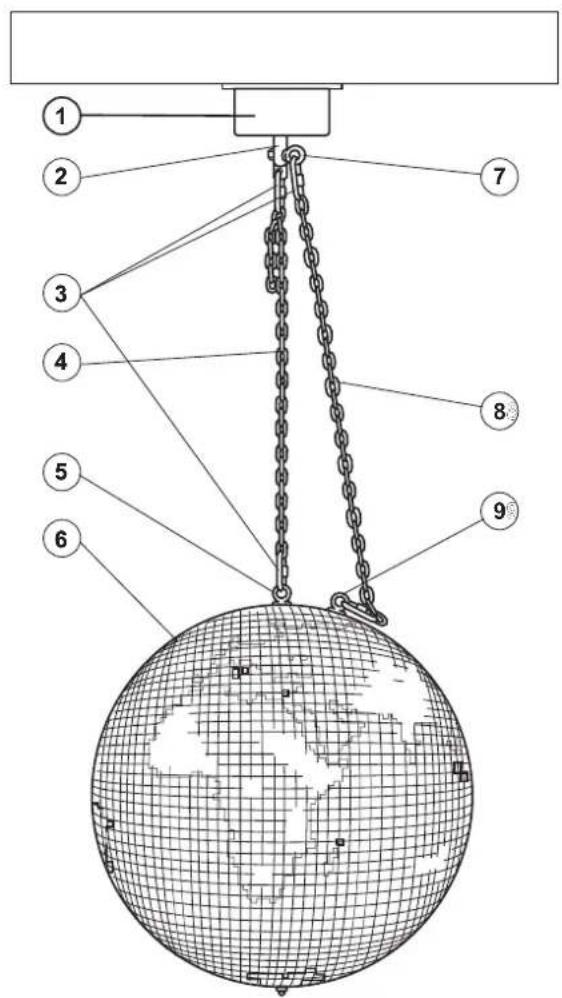
(1) Mirrorball motor
(2) Motor axle
(3) Screw-on chain link
(4) Mirrorball chain
(5) Installation eyelet
(6) Mirrorball
(7) Safety eyelet
(8) Safety chain
(9) Safety eyelet
INSTALLATION
DANGER TO LIFE!
Please consider the EN 60598-2-17 and the respective national norms during the installation! The installation must only be carried out by an authorized dealer!
The installation of the mirrorball has to be built and constructed in a way that it can hold 10 times the weight for 1 hour without any harming deformation.
The installation must always be secured with a secondary safety attachment. This secondary safety attachment must be constructed in a way that no part of the installation can fall down if the main attachment fails.
When rigging, derigging or servicing the fixture staying in the area below the installation place, on bridges, under high working places and other endangered areas is forbidden.
The operator has to make sure that safety-relating and machine-technical installations are approved by an expert before taking into operation for the first time and after changes before taking into operation another time.
The operator has to make sure that safety-relating and machine-technical installations are approved by an expert after every four year in the course of an acceptance test.
The operator has to make sure that safety-relating and machine-technical installations are approved by a skilled person once a year.
Attachment
IMPORTANT! OVERHEAD RIGGING REQUIRES EXTENSIVE EXPERIENCE, including (but not limited to) calculating working load limits, installation material being used, and periodic safety inspection of all installation material and the mirrorball. If you lack these qualifications, do not attempt the installation yourself, but instead use a professional structural rigger. Improper installation can result in bodily injury and/or damage to property.
The motor must only be installed in an absolutely horizontal position at a vibration-free, oscillation-free and fire-resistant location. By using a water-level, make sure that the motor is installed absolutely horizontally and that the motor axle points exactly to the bottom.
The motor and the mirrorball have to be installed out of the reach of people.
If the motor shall be lowered from the ceiling or high joists, professional trussing systems have to be used. The motor must never be fixed swinging freely in the room.
Caution: Mirrorballs may cause severe injuries when crashing down! If you have doubts concerning the safety of a possible installation, do NOT install the motor!
Before attaching the device, make sure that the installation area can hold a minimum point load of 10 times the device's load (e.g. maximum load 3 kg - point load 30 kg).
The mirrorball motor must always be installed via all fixation holes. Do only use appropriate screws and make sure that the screws are properly connected with the ground.
The durability of the installation depends very much on the material used at the installation area (building material) such as wood, concrete, gas concrete, brick etc. This is why the fixing material must be chosen to suit the wall material. Always ask a specialist for the correct plug/screw combination indicating the maximum load and the building material.
Procedure:
Step 1: The fixation holes are located on the baseplate.
Step 2: Hold the baseplate onto the location where the device is to be installed.
Step 3: Mark the boreholes with a pen or a suitable tool.
English
Step 4: Drill the holes.
Step 5: Hold the baseplate in the desired position and tighten it.
The installation material must never include abrading material e. g. steel cables in order to avoid material wearing.
The length of the chain must never exceed 100 cm.
Install the mirrorball chain with the screw-on chain link at the installation eyelet of the mirrorball and tighten the fixation screw.
Insert the fourth chain link of the mirrorball chain with the mirrorball in the screw-on chain link and tighten the fixation screw.
For overhead use, always install a safety chain on the mirrorball that can hold at least 12 times the weight of the installation. The safety chain must be slightly longer than the mirrorball chain so that the safety chain will always be tension-free. Pull the safety chain through the safety eyelet of the mirrorball and in the safety eyelet of the motor.
The maximum drop distance must never exceed 20 cm.
A safety chain which already held the strain of a crash or which is defective must not be used again.
There must never hang a mirrorball or other load at the safety eyelet. Loads must only be hanged at the quick link of the installation eyelet at the motor axle. If a mirrorball hangs for any reason at the safety eyelet, the motor must be taken out of operation immediately and the mirrorball must be uninstalled. The whole installation has to be checked for defects by an expert.
Make sure that the rotation of the mirrorball is never slowed down or stopped by decoration material etc.
Make sure that no side forces can impact on the installation.
Make sure that the mirrorball cannot be moved by air streams. The mirrorball and the motor must be installed and operated absolutely swivel free.
Please check in regular intervals, if the installation material (e.g. key ring, shackles or screw-on chain links) or chain links have been deformed. Uninstall the mirrorball immediately in such a case.
Connection with the mains
Connect the device to the mains with the power plug. The occupation of the connection cables is as follows:
| Cable Pin International | |
| Brown Live L | |
| Blue Neutral N | |
| Yellow/Green Earth | [cxz2] |
Attention! The earth has to be connected!
If the device will be directly connected with the local power supply network, a disconnection switch with a minimum opening of 3 mm at every pole has to be included in the permanent electrical installation.
The device must only be connected with an electric installation carried out in compliance with the IEC standards. The electric installation must be equipped with a Residual Current Device (RCD) with a maximum fault current of 30 mA.
DANGER TO LIFE!
Before taking into operation for the first time, the installation has to be approved by an expert!
CLEANING AND MAINTENANCE
The operator has to make sure that safety-relating and machine-technical installations are inspected by an expert after every four years in the course of an acceptance test.
The operator has to make sure that safety-relating and machine-technical installations are inspected by a skilled person once a year.
The following points have to be considered during the inspection:
1) All screws used for installing the devices or parts of the device have to be tightly connected and must not be corroded.
2) There must not be any deformations on housings, fixations and installation spots (ceiling, suspension, trussing).
3) Mechanically moved parts like axles, eyes and others must not show any traces of wearing (e.g. material abrading or damages) and must not rotate with unbalances.
4) The electric power supply cables must not show any damages, material fatigue (e.g. porous cables) or sediments. Further instructions depending on the installation spot and usage have to be adhered by a skilled installer and any safety problems have to be removed.
Maintenance and service operations are only to be carried out by authorized dealers.
Should you need any spare parts, please use genuine parts.
Should you have further questions, please contact your dealer.
TECHNICAL SPECIFICATIONS
| Power supply: 230 V AC, 50 Hz ~ | |
| Power consumption: 7 W | |
| Max. load WLL (4-fold): 120 kg | |
| Max. load BGV C1 (8-fold): 60 kg | |
| Max. load BGV C1 (10-fold): 50 kg | |
| Max. load BGV C1 (12-fold): 40 kg | |
| Max. diameter of mirror ball: 100 cm (EUROLITE) | |
| Rotation-speed: approx. 1 RPM | |
| Dimensions (LxWxH): 280 x 240 x 110 mm | |
| Poids: 5 kg | |
Please note: Every information is subject to change without prior notice. 04.05.2005 ©
eurolite® GERMANY
MODE D'EMPLOI
eurolite®
MD-3010
- MULTI-LANGUAGE-INSTRUCTIONS
- Français
- Español
- MD-3010 safety rotary motor
- CAUTION!
- INTRODUCTION
- SAFETY INSTRUCTIONS
- Important:
- English
- OPERATING DETERMINATIONS
- DESCRIPTION OF THE DEVICE
- Features
- Mirror ball motor
- Safety features
- INSTALLATION
- DANGER TO LIFE!
- Attachment
- Procedure:
- The installation material must never include abrading material e. g. steel cables in order to avoid material wearing.
- Connection with the mains
- CLEANING AND MAINTENANCE
- TECHNICAL SPECIFICATIONS
- MODE D'EMPLOI
- eurolite®
- MD-3010
Brand : Eurolite
Model : MD3010
Category : Lighting