
3320 - Multimeter PeakTech - Free user manual and instructions
Find the device manual for free 3320 PeakTech in PDF.
| Product Type | Digital Multimeter |
| Brand | PeakTech |
| Model | 3320 |
| Display | LCD 3.5 or 6 digits, 6000 count, backlight |
| Dimensions (L x H x D) | 70 x 150 x 48 mm |
| Weight | 255 g |
| Power Supply | 9 V battery (NEDA 1604 or equivalent) |
| Overvoltage Category | CAT III 600 V |
| Pollution Degree | 2 |
| Max. Input Voltage | 600 V DC/AC rms (10 s max) |
| Max. Input Current | 10 A AC/DC (30 s max every 15 min) |
| Overload Protection | Fuse 10 A / 600 V (6x32 mm, fast-acting) |
| Measurement Functions | AC/DC voltage, AC/DC current, resistance, frequency, capacitance, temperature, diode test, continuity test |
| Special Functions | Data Hold, MIN/MAX, auto/manual ranging, auto power-off (15 min), non-contact voltage detector (>50 V/50 Hz) |
| Operating Temperature Range | 0...50 °C |
| Storage Temperature Range | -20...+60 °C |
| Maintenance and Cleaning | Clean with a damp, lint-free cloth and a mild detergent. Avoid liquid penetration. |
| Battery Replacement | Unscrew the compartment cover, replace with a 9V battery. Observe polarity. |
| Fuse Replacement | Unscrew the cover, replace with a 10A/600V, 6x32mm, 10kA, fast-acting fuse. |
| Repairability | Reserved for qualified service technicians. Unauthorized opening not allowed. |
Frequently Asked Questions - 3320 PeakTech
User questions about 3320 PeakTech
0 question about this device. Answer the ones you know or ask your own.
Ask a new question about this device
Download the instructions for your Multimeter in PDF format for free! Find your manual 3320 - PeakTech and take your electronic device back in hand. On this page are published all the documents necessary for the use of your device. 3320 by PeakTech.
USER MANUAL 3320 PeakTech
© PeakTech® 10/2019 Pt/Po/JTh/Mi
1. Safety Precautions
This product complies with the requirements of the following European Community Directives: 2014/30/EU (Electromagnetic Compatibility) and 2014/35/EU (Low Voltage) as amended by 2014/32/EU (CE-Marking). Overvoltage category III 600V; pollution degree 2.
CAT I: For signal level, telecommunication, electronic with small transient over voltage
CAT II: For local level, appliances, main wall outlets, portable equipment
CAT III: Supplied from a cable under earth; fixed installed switches, automatic cut-off or main plugs
CAT IV: Units and installations, which are supplied overhead lines, which are stand in a risk of persuade of a lightning, i.e. main-switches on current input, overvoltage-diverter, current use counter.
WARNING! Do not use this instrument for high-energy industrial installation measurement.
To ensure safe operation of the equipment and eliminate the danger of serious injury due to short-circuits (arcing), the following safety precautions must be observed.
Damages resulting from failure to observe these safety precautions are exempt from any legal claims whatever.
* Do not exceed the maximum permissible input ratings (danger of serious injury and/or destruction of the equipment).
* The meter is designed to withstand the stated max voltages. If it is not possible to exclude without that impulses, transients, disturbance or for other reasons, these voltages are exceeded a suitable presale (10:1) must be used.
* Do not operate the meter before the cabinet has been closed and screwed safely as terminal can carry voltage.
* Replace a defective fuse only with a fuse of the original rating. Never short-circuit fuse or fuse holding.
* Disconnect test leads or probe from the measuring circuit before switching modes or functions.
* Do not conduct voltage measurements with the test leads connected to the A- and COM-terminal of the equipment.
* To avoid electric shock, disconnect power to the unit under test and discharge all capacitors before taking any resistance measurements.
* Do not conduct current measurements with the leads connected to the V/Ω-terminals of the equipment.
* Check test leads and probes for faulty insulation or bare wires before connection to the equipment.
* To avoid electric shock, do not operate this product in wet or damp conditions. Conduct measuring works only in dry clothing and rubber shoes, i. e. on isolating mats.
* Never touch the tips of the test leads or probe.
* Comply with the warning labels and other info on the equipment.
* Always start with the highest measuring range when measuring unknown values.
* Do not subject the equipment to direct sunlight or extreme temperatures, humidity or dampness.
* Do not subject the equipment to shocks or strong vibrations.
* Do not operate the equipment near strong magnetic fields (motors, transformers etc.).
* Keep hot soldering irons or guns away from the equipment.
* Allow the equipment to stabilize at room temperature before taking up measurement (important for exact measurements).
* Do not turn the rotary function switch during voltage or current measurement; otherwise the meter could be damaged.
* Do not input values over the maximum range of each measurement to avoid damages of the meter.
* Use caution when working with voltages above 35V DC or 25V AC. These Voltages pose shock hazard.
* The measurement instrument is not to be to operated unattended.
* Replace the battery as soon as the battery indicator “BAT” appears. With a low battery, the meter might produce false reading that can lead to electric shock and personal injury.
* Fetch out the battery when the meter will not be used for long period.
* Periodically wipe the cabinet with a damp cloth and mid detergent. Do not use abrasives or solvents.
* The meter is suitable for indoor use only
* Do not store the meter in a place of explosive, inflammable substances.
* Opening the equipment and service – and repair work must only be performed by qualified service personnel
* Do not modify the equipment in any way
* -Measuring instruments don't belong to children hands.-
Cleaning the cabinet
Clean only with a damp, soft cloth and a commercially available mild household cleanser. Ensure that no water gets inside the equipment to prevent possible shorts and damage to the equipment.
1.1. Input limits
| V DC or V AC | 600 V DC/ACrms |
| 10 A DC/AC | 10 A AC/DC less than 30 sec. each 15 min.(fused 10A / 600V - Fuse) |
| Frequency | 600 V DC or ACrms |
| Resistance | 600 V DC or ACrms, max. 10 sec. |
| Duty cycle | 600 V DC or ACrms |
| Capacity | 600 V DC or ACrms |
| Diode | 600 V DC or ACrms |
| Continuity | 600 V DC or ACrms |
| Temperature | 600 V DC or ACrms |
1.2. Safety Symbols
 | This symbol adjacent to another symbol, terminal or operating device indicates that the operator must refer to an explanation in the operating instructions to avoid personal injury or damage to the meter. |
 | This symbol advices the user that the terminals so marked must not be connected to a circuit point at which the voltage, with respect to earth ground, exceeds (in this case) 600 V AC or VDC |
 | This WARNING symbol indicates potentially hazardous situation, which if not avoided, could result in death or serious injury. |
 | This CAUTION symbol indicates a potentially hazardous situation, which if not avoided, may result in minor or moderate injury, or damage to the product or other property. |
 | This symbol adjacent to one or more terminals identifies them as being associated with ranges that may, in normal use, be subjected to particularly hazardous voltages. For maximum safety the meter and its test leads should not be handled when these terminals are energized. |
2. Technical Data
2.1. Specifications
| Display | 3 5/6-digit LCD-display with max. display of 6000, automatic Polarity-display and Backlight. |
| Overrange indicaton | "OL" |
| Low battery indication | Battery symbol indicates low battery condition |
| Measuring rate | 3 times / sec. |
| Auto power off | about 15 min. |
| Data HoldRelative ModeMIN / MAX - ModeAuto / manual Ranging | |
| Operating Temperature | 0°C to 50°C (32°F to 122°F) < 70 % RH |
| Storage Temperature | -20...+60°C (-4°F to 140°F) < 80 % RH |
| Accuracy Temperature | 18°C to 28°C (64°F to 82°F) to maintain guaranteed accuracy |
| Dimensions (W x H x D) | 70 x 150 x 48 mm |
| Weight | 255 g |
| Power source | 9 V battery (Neda 1604) |
2.2. Electrical Specifications
Input Resistance: 10 MΩ
Max. Input voltage: 600 V DC / AC _eff
DC Voltage
| Range | Resolution | Accuracy |
| 600 mV | 0.1 mV | ± 0.5% rdg. + 2 dgt. |
| 6 V | 1 mV | ± 1.0% rdg. + 2 dgt. |
| 60 V | 10 mV | |
| 600 V | 100 mV | |
| 1000 V | 1 V | ± 1.2% rdg. + 2 dgt. |
AC Voltage
| Range | Resolution | Accuracy |
| 6.000V | 1mV | ±(1.0% + 5 dgt.) |
| 60.00V | 10mV | ±(1.2% + 5 dgt.) |
| 600.0V | 0.1V | ±(1.5% + 5 dgt.) |
| 1000V | 1V | |
| All AC voltage ranges are specified from 5% of range to 100% of range .AC VoltageBandwidth:50HZ to 60HZ(ALL WAVE) 50Hz to 1kHz(SINE WAVE) | ||
Input Resistance: 10 MΩ
Max. Input voltage: 600 V DC / AC _eff
DC Current
| Range | Resolution | Accuracy |
| 6 A | 1 mA | ± 2.5% v. M. + 5 dgt. |
| 10 A | 10 mA |
Overload protection:
Max. Input voltage: 10 A/600 V Fuse
10 A DC/AC
(10 A for max. 30 sec.)
eff at 10 A Input
AC Current
| Range | Resolution | Accuracy |
| 6 A | 1 mA | ± 2.5% rdg + 5 dgt. |
| 10 A | 10 mA |
Overload protection:
Max. Input Current: 10 A/600 V Fuse
10 A DC/AC
rms at 10 A-Input
(10 A for max. 30 sec.).
Frequency range: True RMS Measurement 50...60 Hz
Resistance
| Range | Resolution | Accuracy |
| 600 Ω | 0,1 Ω | ± 1.2% rdg. + 2 dgt. |
| 6 kΩ | 1 Ω | ± 1.2% rdg. + 2 dgt. |
| 60 kΩ | 10 Ω | ± 1.2% rdg.. + 2 dgt. |
| 600 kΩ | 100 Ω | |
| 6 MΩ | 1 kΩ | ± 2.0% rdg. + 2 dgt. |
| 60 MΩ | 10 kΩ | ± 3.5% rdg. + 10 dgt. |
Overload protection: 600 V DC/ACrms
Frequency
| Range | Resolution | Accuracy |
| 9.999Hz | 0.001Hz | ±(1.2% + 5 dgt.) |
| 99.99Hz | 0.01Hz | |
| 999.9Hz | 0.1Hz | |
| 9.999kHz | 1Hz | |
| 99.99kHz | 10Hz | |
| 999.9kHz | 100Hz | ±(1.5% + 5 dgt.) |
| 9.999MHz | 1kHz |
Sensitivity: >0,5 V
rms at < 1 MHz
3 V
rms at > 1 MHz
Overload protection: 600 V DC/AC
rms
Overload protection: 600 V DC/AC
rms
Capacitance
| Range | Resolution | Accuracy |
| 9.999nF | 0.001nF | ±(5.0% +80 dgt.) |
| 99.99nF | 0.01nF | ±(3.0% +5 dgt.) |
| 999.9nF | 0.1nF | |
| 9.999μF | 0.001μF | ±(3.5% +5 dgt.) |
| 99.99μF | 0.01μF | |
| 999.9μF | 0.1μF | |
| 9.999mF | 1uF | ±(5.0% +10 dgt.) |
| 99.99mF | 10uF | ±(5.0% +35 dgt.) |
Temperature
| Range | Resolution | Accuracy |
| -4°F ... 1472°F | 0.1°F | ±(1.5% + 9°F) |
| -20°C ... 800°C | 0.1°C | ±(1.5% + 5°C) |
Sensor: Type-K Temperature-probe
Overload protection: 600 V DC/ACrms
Diode-Test
Open circuit voltage 3 V DC typ.
Test current 1 mA max.
Protection 600 V DC/AC
eff
Continuity
Acoustic signal at < 50 Ω
Remark:
Mentioned Accuracy in % + Number of digits
3. Controls and Jacks
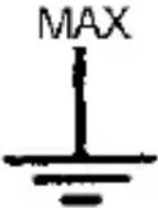
text_image
10. 1.332 1.332 HOLD MAX MINT RANGE 8. 9. TRUE RMS 7. 6. 8. CAP Hz °C Ω F 10A 10A OFF Auto Power Off 10A COM VDD-HZ CAP TEMP For 30 sec. MAX every 15 min. PUMED CCT B-880 CCT B-100W 5. 4. 3.(1) 3 5/6-digit LCD-Display
(2) Function - Switch
(3) V / Ohm / Hz / Cap (positive) Input-Jack
(4) COM-(negative) Input-Jack
(5) 10A-Input-Jack
(6) RANGE-Hold push button; diode/cont. select button
(7) LED for non-contact voltage detector
(8) MIN/MAX-Button
(9) Data – Hold – Button; backlight
(10) AC voltage detector sensor
4. Operating instructions
Warning!
Risk of electrocution. High-voltage circuits, both AC and DC are very dangerous and should be measured with great care.
- Always push the power pushbutton to the OFF position when the meter is not in use. This meter has Auto OFF that automatically shuts the meter OFF if 15 minutes elapse between uses.
- If "OL" appears in the display during a measurement, that value you are measuring exceeds the range you have selected. Change to higher range.
4.1. Preliminary Note
- Check the 9 V battery by setting the ON/OFF switch to ON. If the battery is weak, a "LO BAT" or "BAT" sign will appear on the left of display. If this does not appear on the display proceed as below. See "Maintenance" if the battery has to be replaced.
- The warning sign next to the test leads jack is for warning, that the input voltage or current should not exceed the indicated values. This is to prevent damage to the internal circuitry.
- The function switch should be set to the range, which you want to test before operation.
Note:
On some low AC and DC voltage ranges, with the test leads not connected to a device, the display may show a random, changing reading. This is normal and is caused by the high-input sensitivity. The reading will stabilize and give a proper measurement when connected to a circuit.
4.2. Autoranging / manual range selection
When the meter is first turned on, it automatically goes into Auto-Ranging. This automatically selects the best range for the measurements being made and is generally the best mode for most measurements. For measurement situations requiring that the range be manually held, perform the following:
- Press the "RANGE" button. The "AUTO" indicator will extinguish and the currently selected range will be held.
- Press the "RANGE" button to step through the available ranges until you select the range you want.
- Press and hold the "RANGE" button for 2 seconds to exit the manual ranging mode and return to "AUTO" mode.
4.3. Backlight
The backlight function is used to illuminate the display when the meter is used at night or in dimly lighted area.
-
Press the "HOLD" button for 2 seconds and backlight will be activated.
-
Press the "HOLD" button again for 2 seconds to remove the backlight function. The backlight turns off automatically after 10 seconds.
5. Measuring
5.1. Data Hold
The data hold function allows the meter to "freeze" a measurement for later reference.
- Press the "HOLD" button to freeze the display, the "HOLD" indicator will appear in the display.
- Press the "HOLD" button to return to normal operation.
5.2. Min./Max.-Hold
This function shows the min. - and max. value in the display. Follow the described procedure to activate this function.
- Press RANGE-button to reach the respective measuring range, to make sure, that the measured MIN./MAX.-value will fall under or exceeds the measuring range.
- Press MIN/MAX-button to reach the MIN/MAX-function.
- Place the test leads to the circuit to be measured.
- Readout and analyse the measured value in the LCD-Display.
- For leaving the MIN/MAX-function, press the MIN/MAX-button for 2 seconds.
5.3. DC Voltage measurements
Caution:
Do not measure DC voltages if a motor on the circuit is being switched ON or OFF. Large voltage surges may occur during the ON or OFF operations that can damage the meter.
- Set the function switch to the "V ---" position.
- Insert the black test lead into the negative COM jack and the red test lead into the positive V/Ω-jack.
- Touch the test probe tips to the circuit under test. Be sure to observe the correct polarity (red lead to positive, black lead to negative).
- Read the voltage in the display. The display will indicate the proper decimal point and value. If the polarity is reserved, the display will show (-) minus before the value.
5.4. AC Voltage measurements
Warning:
Risk of Electrocution. The probe tips may not be long enough to contact the live parts inside some 230 V outlets for appliances because the contacts are recessed deep in the outlets. As a result, the reading may show 0 volts when the outlet actually has voltage on it. Make sure the probe tips are contacting the metal contacts inside the outlet before assuming that no voltage is present.
Caution:
Do not measure AC voltages if a motor on the circuit is being switched ON or OFF. Large voltage surges may occur during the ON or OFF operations that can damage the meter.
- Set the function switch to the "V \~" position.
- Insert the black test lead into the negative COM jack and the red test lead into the positive V/Ω jack.
- Touch the test probe tips to the circuit under test.
- Read the voltage in the display. The display will indicate the proper decimal point, value and symbol.
5.5. DC Current measurement
Caution:
Do not make current measurements on the 10 A scale for longer than 30 sec. Exceeding 30 sec. may cause damage to the meter and / or the test leads.
- Insert the black test lead into the negative COM jack.
-
Set the function switch to the 10 A ... position and insert the red test lead into the 10 A jack.
-
Remove power from the circuit under test and open the circuit at the point where you wish to measure current.
- Touch the black test probe tip to the negative side of the circuit and touch the red test probe tip to the positive side of the circuit.
- Apply power to the circuit.
- Read the current in the display. The display will indicate the proper decimal point, value and symbol.
5.6. AC Current measurements
Caution:
Do not make current measurements on the 10 A scale for longer than 30 sec. Exceeding 30 sec. may cause damage to the meter and/or the test leads.
- Insert the black test lead into the negative COM jack.
- Set the function switch to the 10 A \~ position and insert the red test lead into the 10 A jack.
- Remove power from the circuit under test and open the circuit at the point where you wish to measure current.
- Touch the black test probe tip to the negative side of the circuit and touch the red test probe tip to the positive side of the circuit.
- Apply power to the circuit.
- Read the current in the display. The display will indicate the proper decimal point, value and symbol.
5.7. Resistance measurements
Warning:
To avoid electric shock, disconnect power to the unit under test and discharge all capacitors before taking any resistance measurements.
Remove the batteries and unplug the line cords.
-
Set the function switch to the " " position.
-
Insert the black test lead into the negative COM jack and the red test lead into the positive jack.
- Touch the test probe tips across the circuit or part under test. It is best to disconnect one side of the part under test so the rest of the circuit will not interfere with the resistance reading.
- Read the resistance in the display. The display will indicate the proper decimal point, value and symbol.
Note:
When you short the test leads in the 600 Ω range, your meter display a small value (no more than 0.3 Ω). This value is due to your meter's and test leads internal resistance. Make a note of this value and subtract it from small resistance measurements for better accuracy.
5.8. Frequency measurement
- Set the function switch to the "Hz" position.
- Insert the black test lead into the negative COM jack and the red test lead into the positive Hz jack.
-
Touch the test probe tips to the circuit under test.
-
Read the frequency in the display. The digital reading will indicate the proper decimal point, symbols (Hz, kHz, MHz) and value.
5.9. Capacitance measurements
Warning:
To avoid electric shock, disconnect power to the unit under test and discharge all capacitors before taking any capacitance measurements. Remove the batteries and unplug the line cords.
- Set the function switch to the "CAP" position.
- Insert the black test lead into the negative COM jack and the red test lead into the positive V/Ω/CAP-jack.
- Touch the test leads to the capacitor to be tested. The display will indicate the proper decimal point, value and symbol.
5.10. Temperature measurements
Warning:
To avoid electric shock, disconnect both test probes from any source of voltage before making a temperature measurement.
-
Insert the adapter in the input socket (+ to V/Ω and - to COM-socket) for temperature measurements.
-
Insert the temperature probe into the temperature adaptor, making sure to observe the correct polarity.
- Touch the temperature probe head to the part whose temperature you wish to measure. Keep the probe touching the part under test until the reading stabilize (about 30 seconds).
- Read the temperature in the display. The digital reading will indicate the proper decimal point and value.
Warning:
To avoid electric shock, be sure the thermocouple has been removed before changing to any other measurement function.
5.11. Diode test
Warning:
To avoid electric shock, do not test any diode that has voltage on it.
- Set the function switch to " " position.
-
Press the "RANGE" button until the " " symbol appears in the display.
-
Insert the black test lead into the negative COM jack and the red test lead into the positive V/Ω jack.
-
Touch the test probe tips to the diode or semiconductor junction you wish to test. Note the meter reading.
-
Reverse the probe polarity by switching probe position. Note this reading.
-
The diode or junction can be evaluated as follows:
A: If one reading shows a value and the other reading shows OL, the diode is good.
B: If both readings are OL, the device is open.
C: If both readings are very small or 0, the device is shorted.
Note: The value indicated in the display during the diode check is the forward voltage.
5.12. Continuity check
Warning:
To avoid electric shock, never measure continuity on circuits or wires that have voltage on them.
-
Set the function switch to the " / *))) " -position.
-
Insert the black test lead into the negative COM jack and the red test lead into the positive V/Ω jack.
- Press the "RANGE" push button until the "◀ ))") symbol appears in the display.
- Touch the test probe tips to the circuit or wire you wish to check.
- If the resistance is less than 100 ohms, the audible signal will sound. The display will also show the actual resistance.
5.13. Non-Contact Voltage (NCV) - Detector
The NCV function works on any rotary switch position.
- Test the detector on a known live circuit before use.
- Hold the top of the meter very close to the voltage source as shown.
- If voltage is present, the rim of the LCD display will flash a bright red.
Note:
The NCV detector works from approx. 50V / 50Hz or higher.
6. Replacing the battery
Warning:
To avoid electric shock, disconnect the test leads from any source of voltage before removing the back cover or the battery/fuse door.
-
Disconnect the test leads from the meter.
-
Open the battery/fuse door by loosening the screws on the battery/fuse door using a screw-driver.
- Clip the new battery into battery holder, observing the correct polarity.
- Place the battery into the battery/fuse compartment.
- Put the battery/fuse door back in place. Secure with the screws.
- Dispose of the old battery properly
Warning:
To avoid electric shock, do not operate your meter until the back cover and the battery / fuse door is in place and fastened securely.
Note:
If your meter does not work properly, check the fuses and batteries to make sure that they are still good and that they are properly inserted.
Notification about the Battery Regulation
The delivery of many devices includes batteries, which for example serve to operate the remote control. There also could be batteries or accumulators built into the device itself. In connection with the sale of these batteries or accumulators, we are obliged under the Battery Regulations to notify our customers of the following:
Please dispose of old batteries at a council collection point or return them to a local shop at no cost. The disposal in domestic refuse is strictly forbidden according to the Battery Regulations. You can return used batteries obtained from us at no charge at the address on the last side in this manual or by posting with sufficient stamps.
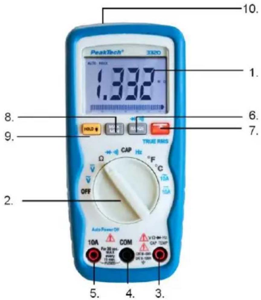
Contaminated batteries shall be marked with a symbol consisting of a crossed-out refuse bin and the chemical symbol (Cd, Hg or Pb) of the heavy metal which is responsible for the classification as pollutant:
- "Cd" means cadmium.
- "Hg" means mercury.
- "Pb" stands for lead.
7. Replacing the fuses
Warning:
To avoid electric shock, do not operate your meter until the battery / fuse door is in place and fastened securely.
- Disconnect the test leads from the meter and any item under test.
- Open the battery/fuse door by loosening two screws on the battery/fuse door using a screw-driver.
- Remove the old fuse from its holder by gently pulling it out.
- Install the new fuse into the holder.
- Always use a fuse of the proper size and value 10A/600 V; 6x32mm; 10 kA; fast blow for the 10 A range.
- Put the battery/fuse door back in place. Insert the screws and tighten it securely.
Warning:
To avoid electric shock, do not operate your meter until the back cover and the battery / fuse door is in place and fastened securely.
All rights, also for translation, reprinting and copy of this manual or parts are reserved.
Reproduction of all kinds (photocopy, microfilm or other) only by written permission of the publisher.
This manual considers the latest technical knowing. Technical changings which are in the interest of progress reserved.
We herewith confirm, that the units are calibrated by the factory according to the specifications as per the technical specifications. We recommend to calibrate the unit again, after 1 year.
© PeakTech® 10/2019 Pt/Po/JTh/Mi
effective 50... 60 Hz
Résistance
| Plage | Résolution | Précision |
| 600 Ω | 0,1 Ω | ± 1,2% v. M. + 2 St. |
| 6 kΩ | 1 Ω | ± 1,2% v. M. + 2 St. |
| 60 kΩ | 10 Ω | ± 1,2% v. M. + 2 St. |
| 600 kΩ | 100 Ω | |
| 6 MΩ | 1 kΩ | ± 2,0% v. M. + 2 St. |
| 60 MΩ | 10 kΩ | ± 3,5% v. M. + 10 St. |
| Plage | Résolution | Précision |
| 9.999nF | 0.001nF | ±(5.0% +80) |
| 99.99nF | 0.01nF | ±(3.0% +5) |
| 999.9nF | 0.1nF | |
| 9.999μF | 0.001μF | ±(3.5% +5) |
| 99.99μF | 0.01μF | |
| 999.9μF | 0.1μF | |
| 9.999mF | 1uF | ±(5.0% +10) |
| 99.99mF | 10uF | ±(5.0% +35) |
Protection anti-surcharge 600 V DC/AC eff
Remarque :
chemical
Three types of radioactive metal compounds: Cd¹, Hg², and Pb³, each represented by a schematic diagram with crossed lines indicating disordered or crossed-out conditions.- "Cd" signifie "cadmium".
- "Hg" signifie "mercure".
- "Pb" signifie "plomb".
© PeakTech® 10/2019 Pt/Po/EHR/JTh/Mi