
NVD2120 - Receiver NUVO - Free user manual and instructions
Find the device manual for free NVD2120 NUVO in PDF.
| Product Type | Audio/Video Receiver |
| Brand | NUVO |
| Model | NVD2120 |
| Dimensions (W x D x H) | Approx. 430 x 300 x 100 mm |
| Weight | Approx. 5 kg |
| Power Supply | 220-240 V ~ 50/60 Hz |
| Power Consumption | 150 W (operation), < 0.5 W (standby) |
| HDMI Inputs | 3 inputs, 1 output (ARC) |
| Digital Audio Inputs | 1 optical, 1 coaxial |
| Analog Audio Inputs | 2 stereo RCA pairs |
| Speaker Output | 5.1 channels (screw terminals) |
| Output Power | 50 W per channel (8 Ω, 0.1% THD) |
| Connectivity | Bluetooth (reception), no Wi-Fi |
| Remote Control | Yes, included with batteries |
| Display | LED screen on front panel |
| Maintenance and Cleaning | Unplug before cleaning, use a dry cloth |
| Safety | Do not expose to moisture, do not open the chassis |
| Spare Parts and Repairability | Parts not available online, repair by qualified technician |
| Included Accessories | Power cord, remote control, user manual |
Frequently Asked Questions - NVD2120 NUVO
User questions about NVD2120 NUVO
0 question about this device. Answer the ones you know or ask your own.
Ask a new question about this device
Download the instructions for your Receiver in PDF format for free! Find your manual NVD2120 - NUVO and take your electronic device back in hand. On this page are published all the documents necessary for the use of your device. NVD2120 by NUVO.
USER MANUAL NVD2120 NUVO
text_image
NUVO® MODEL: NV-D2120 Digital Power Amplifier, 2x120W POWER STARDAY ACTIVE TEMP FAULT TEMP FAULT L R U UNIT ON AMPLIFIER SENSITIVITY POWER MODES POWER MODES TROGGER IN 1.5V/30Hz A2.0GHz +200V 500Hz SPEAKER OUTPUT POWER SPEAKER SHEMORATE 4.0Ω/Hz 8.0Ω/Hz 0.6V/30Hz 1.5V/Hz 2.3 POTATO POWER 0950-4333 NVO® MODEL NOODERS Digital Power Amplifier Multi Technologies LLC + VDDA, CV/USA Power Supply Control Unit 1.5V/Hz Power Supply Control Unit 2.5V/Hz Power Supply Control Unit 3.5V/Hz Power Supply Control Unit 4.5V/Hz Power Supply Control Unit 5.5V/Hz Power Supply Control Unit 6.5V/Hz Power Supply Control Unit 7.5V/Hz Power Supply Control Unit 8.5V/Hz Power Supply Control Unit 9.5V/Hz Power Supply Control Unit 10.5V/Hz Power Supply Control Unit 11.5V/Hz Power Supply Control Unit 12.5V/Hz Power Supply Control Unit 13.5V/Hz Power Supply Control Unit 14.5V/Hz Power Supply Control Unit 15.5V/Hz Power Supply Control Unit 16.5V/Hz Power Supply Control Unit 17.5V/Hz Power Supply Control Unit 18.5V/Hz Power Supply Control Unit 19.5V/Hz Power Supply Control Unit 20.5V/Hz Power Supply Control Unit 21.5V/Hz Power Supply Control Unit 22.5V/Hz Power Supply Control Unit 23.5V/Hz Power Supply Control Unit 24.5V/Hz Power Supply Control Unit 25.5V/Hz Power Supply Control Unit 26.5V/Hz Power Supply Control Unit 27.5V/Hz Power Supply Control Unit 28.5V/Hz Power Supply Control Unit 29.5V/Hz Power Supply Control Unit 30.5V/Hz Power Supply Control Unit 31.5V/Hz Power Supply Control Unit 32.5V/Hz Power Supply Control Unit 33.5V/Hz Power Supply Control Unit 34.5V/Hz Power Supply Control Unit 35.5V/Hz Power Supply Control Unit 36.5V/Hz Power Supply Control Unit 37.5V/Hz Power Supply Control Unit 38.5V/Hz Power Supply Control Unit 39.5V/Hz Power Supply Control Unit 40.5V/Hz Power Supply Control Unit 41.5V/Hz Power Supply Control Unit 42.5V/Hz Power Supply Control Unit 43.5V/Hz Power Supply Control Unit 44.5V/Hz Power Supply Control Unit 45.5V/Hz Power Supply Control Unit 46.5V/Hz Power Supply Control Unit 47.5V/Hz Power Supply Control Unit 48.5V/Hz Power Supply Control Unit 49.5V/Hz Power Supply Control Unit 50.5V/HzNV-D2120 External Power Amplifier
Installation Guide
ENGLISH
Danger
Exposure to extremely high noise levels may cause a permanent hearing loss. Individuals vary considerably to noise induced hearing loss but nearly everyone will lose some hearing if exposed to sufficiently intense noise for a sufficient time. The U.S. Government's Occupational Safety and Health Administration (OSHA) has specified the following permissible noise level exposures:
| DURATION PER DAY (HOURS) | 8 | 6 | 4 | 3 | 2 | 1 |
| SOUND LEVEL (dB) | 90 | 93 | 95 | 97 | 100 | 103 |
According to OSHA, any exposure in the above permissible limits could result in some hearing loss. Ear plugs or protectors in the ear canal or over the ears must be worn when operating this amplification system in order to prevent a permanent hearing loss. If exposure in excess of the limits as put forth above, to insure against potentially harmful exposure to high sound pressure levels, it is recommended that all persons exposed to equipment capable of inducing high sound pressure levels, such as this amplification system, be protected by hearing protectors while this unit is in operation.
text_image
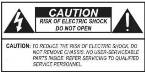
CAUTION RISK OF ELECTRIC SHOCK DO NOT OPEN CAUTION: TO REDUCE THE RISK OF ELECTRIC SHOCK, DO NOT REMOVE CHASSIS. NO USER-SERVICEABLE PARTS INSIDE. REFER SERVICING TO QUALIFIED SERVICE PERSONNEL.AVIS: RISQUE DE CHOC ELECTRIQUE-NE PAS OUVRIR.

THIS SYMBOL IS INTENDED TO ALERT THE USER TO THE PRESENCE OF NON-INSULATED "DANGEROUS VOLTAGE" WITHIN THE PRODUCT'S ENCLOSURE THAT MAY BE OF SUFFICIENT MAGNITUDE TO CONSTITUTE A RISK OF ELECTRIC SHOCK TO PERSONS.

THIS SYMBOL IS INTENDED TO ALERT THE USER TO THE PRESENCE OF IMPORTANT OPERATING AND MAINTENANCE (SERVICING) INSTRUCTIONS IN THE LITERATURE ACCOMPANYING THE UNIT.

APPARATUS SHALL NOT BE EXPOSED TO DRIPPING OR SPLASHING AND THAT NO OBJECTS FILLED WITH LIQUIDS, SUCH AS VASES, SHALL BE PLACED ON THE APPARATUS.
IMPORTANT SAFETY INSTRUCTIONS
- Read all safety and operating instructions before using this product.
- All safety and operating instructions should be kept for future reference.
- Read and understand all warnings listed on the operating instructions.
- Follow all operating instructions to operate this product.
- This product should not be used near water, i.e. Bathtub, sink, swimming pool, wet basement, etc.
- Only use dry cloth to clean this product.
- Do not block any ventilation openings, It should not be placed flat against a wall or placed in a built-in enclosure that will impede the flow of cooling air.
- Do not install this product near any heat sources; such as, radiators, heat registers, stove or other apparatus (including heat producing amplifiers) that produce heat.
- Do not defeat the safety purpose of the polarized or grounding-type plug. A polarized plug has two blades with one wider than the Other. A grounding-type plug has two blades and a third grounding prong. The wide blade or the third prong are provided for your safety If the provided plug does not fit into your outlet, consult an electrician for replacement of the obsolete outlet.
- Protect the power cord being walked on or pinched, particularly at Plugs, convenience receptacles and the point where they exit from the apparatus. Do not break the ground pin of the power supply cord.
- Only use attachments specified by the manufacturer.
- Use only with the cart, stand, tripod, bracket, or table specified by the manufacturer or sold with the apparatus. When a cart is used, use caution when moving cart/apparatus combination to avoid
injury from tip-over.

- Unplug this apparatus during lightning storms or when unused for long periods of time.
- Care should be taken so that objects do not fall and liquids are not spilled into the unit through the ventilation ports or any other openings.
- Refer all servicing to qualified service personnel. Servicing is required when the apparatus has been damaged in any way; such as, power-supply cord or plug is damaged, liquid has been spilled or objects have fallen into the apparatus, the apparatus has been exposed to rain or moisture, does not operate normally or has been dropped.
- WARNING: To reduce the risk of fire or electric shock, do not expose this apparatus to rain or moisture.
FRENCH
Danger
FCC Radio Frequency Interference Statement Warning
This equipment has been tested and found to comply with the limits for Class B digital device, pursuant to Part 15 of the FCC rules. These limits are designed to provide reasonable protection against harmful interference in a residential installation. This equipment generates, uses, and can radiate radio frequency energy and, if not installed and used in accordance with the instructions, it may cause harmful interference to radio communications. However, there is no guarantee that interference will not occur in a particular installation. If this equipment does cause harmful interference to radio or television reception, which can be determined by turning the equipment off and on, the user is encouraged to try to correct the interference by one or more of the following measures:
- Reorient or relocate the receiving antenna.
- Increase the separation between the equipment and the receiver.
- Connect the equipment into an outlet on a circuit different from that to which the receiver is connected.
- Consult the dealer or an experienced radio/TV technician for assistance.
This device complies with Part 15 of the FCC rules. Operation is subject to the following two conditions: (1) This device may not cause harmful interference, and (2) this device must accept any interference received, including interference that may cause undesired operation.

EN55022 Class-B
EN55024

IC Statement
This class B digital apparatus complies with Canadian ICES-003.
Introduction
Congratulations on your purchase of the NuVo NV-D2120 Digital Power Amplifier. This robust amplifier will provide 120 watts to each of its two speaker outputs, allowing for versatile uses powering any indoor or outdoor audio zone in multiple speaker configurations. Now with the ENERGY STAR rating, this single rack space mountable unit will provide quality audio to your speakers while consuming less power than other standalone amplifiers.
Stable at four or eight ohms, and with multiple trigger options, the NV-D2120 offers the ultimate flexibility with the quality of construction you have come to expect from NuVo Technologies.
Table of Contents:
Introduction......Page 6
Front Panel Page 7
Back Panel Page 8
Wiring Diagram......Page 9
I. Audio Inputs......Page 10
II Sensitivity Control......Page 11
III. Power Mode......Page 11
IV. Trigger In......Page 13
V. Unit On....Page 13
VI. Speaker Impedance......Page 13
VII. Speaker Outputs......Page 14
Specifications......Page 15
NV-D2120 Package Contents
SKU Description Quantity
NV-D2120 Digital Power Amplifier 1
NV-CMRS3B-A Mini to RCA Stereo Audio Cable 1
NV-REM1U-C Single Space Rack Ear Mount (pair) 1
NV-PC2-NA-A North American 2-wire Power Cable 1
NV-CMM3B 3.5MM Mini Mono Cable 1
text_image
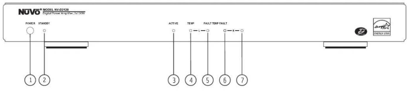
NOVO® MODEL NV-D2120 Digital Power Amplifier, 3x10W POWER STANDBY 1 2 ACTIVE TEMP FAULT TEMP FAULT 3 4 5 6 7 ENERGY STARFront Panel Features
- Power Button: Pushing this button will manually supply power to the amplifier. The amplifier is designed to remain in standby mode when not in use.
- Standby: This LED (light emitting diode) will light blue when the D2120 is plugged into an A/C power supply.
- Active: This yellow LED lights to indicate that the amplifier is in normal amplification mode.
- Temp: This will light red to indicate that the left channel of the amplifier has overheated.
- Fault: This will light red to indicate that the left channel of the amplifier is experiencing issues not related to temperature/overheating.
- Temp: This will light red to indicate that the right channel of the amplifier has overheated.
- Fault: This will light red to indicate that the right channel of the amplifier is experiencing issues not related to temperature/overheating.
text_image
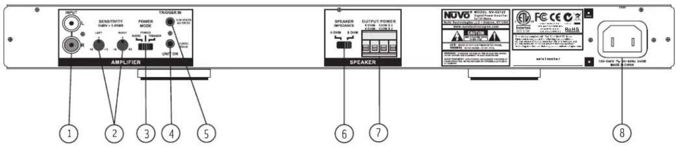
INPUT SENSITIVITY TURB = LUMBER POWER MODE TROGER IN UNIT ON AMPLIFIER SPEAKER INDEPENDENCE OUTPUT POWER & CHAM & CHAW SPEAKER NOVO MODEL NV-0212E Digital Power Amplifier R1300000000000000000000000000000000000000000000000000000000000000000000000000000000000 www.rsc.org/163.com CAUTION FOR FUTURES FOR FUTURES FOR FUTURES FOR FUTURES FOR FUTURES FOR FUTURES FOR FUTURES FOR FUTURES FOR FUTURES FOR FUTURES FOR FUTURES FOR FUTURES FOR FUTURES FOR FUTURES FOR FUTURES FOR FUTURES FOR FUTURES FOR FUTURES FOR FUTURES FOR FUTURES FOR FUTUNION FOR FUTUNION FOR FUTUNION FOR FUTUNION FOR FUTUNION FOR FUTUNION FOR FUTUNION FOR FUTUNION FOR FUTUNION FOR FUTUNION FOR FUTUNION FOR FUTUNION FOR FUTUNION FOR FUTUNION FOR FUTUNION FOR FUTUNION FOR FUTUNION FOR FOTUNION FOR FOTUNION FOR FOTUNION FOR FOTUNION FOR FOTUNION FOR FOTUNION FOR FOTUNION FOR FOTUNION FOR FOTUNION FOR FOTUNION FOR FOTUNION FOR FOTUNION FOR FOTUNION FOR FOTUNION FOR FOTUNION FOR FOTUNION FOR FOTUNION FCC CE CCE CCE CCE CCE CCE CCE CCE CCE CCE CCE CCE CCE CCE CCE CCE CCE CCE CCE CCE CCE CCE CCE CCE CCE CCE CCE CCE CCE CCE CCE CCE CCE CCE CCE CCE CCE CCE CCE CCE CCE CCE CCE CCE CCE CCE CCE CCE CCE CCE CCE Cce Cce Cce Cce Cce Cce Cce Cce Cce Cce Cce Cce Cce Cce Cce Cce Cce Cce Cce Cce Cce Cce Cce Cce Cce Cce Cce Cce Cce Cce Cce Cce Cce Cce Cce Cce Cce Cce Cce Cce Cce Cce Cce Cce Cce Cce Cce Cce Cce Cce Ccc CE CE CE CE CE CE CE CE CE CE CE CE CE CE CE CE CE CE CE CE CE CE CE CE CE CE CE CE CE CE CE CE CE CE CE CE CE CE CE CE CE CE CE CE CE CE CE CE CE CE CE CE CE CE CE CE CE CE CE CE CE CE CE CE CE CE CE CE CE CE CE CE CE CE CE CE CE CE CE CE CE CE CE CE CE CE CE CE CE CE CE CE CE CE CE CE CE CE CE CE 8Back Panel Features
- Audio Source Input: The D2120 will accept any line level stereo audio signal. This can be from the preamp lineout of a multi-source, multi-zone whole house system such as the NuVo Essentia E6G and Grand Concerto systems, or the audio output of any non-amplified source, such as an AM/FM tuner, CD player, or Satellite receiver.
- Sensitivity Gain Control: Left and Right Channel Sensitivity trim pots allow the incoming signal to be increased or decreased to maximize the potential output of the audio source.
- Power Mode: This switch dictates how the amplifier responds to external triggers. The D2120 has 3 trigger methods: Incoming audio signal, external voltage input, or the power button on the front of the amplifier.
- Unit On: This provides a 12V trigger output when the amplifier is powered on. This can be used to turn on external audio equipment, daisy chain multiple external amplifiers, or trigger a relay switching power strip.
- Trigger In: This voltage trigger input allows the D2120 to power up whenever a voltage of 3-30 volts AC or DC is present.
- Speaker Impedance: This switch sets the impedance stability at either four or eight ohms.
- Speaker Output: The speaker output attaches to the amplifier via a modular plug and provides 120 Watts per channel output at either 4 or 8 ohms.
- AC Power: The D2120 is designed to plug into any AC power source.
NV-D2120 Wiring Diagram
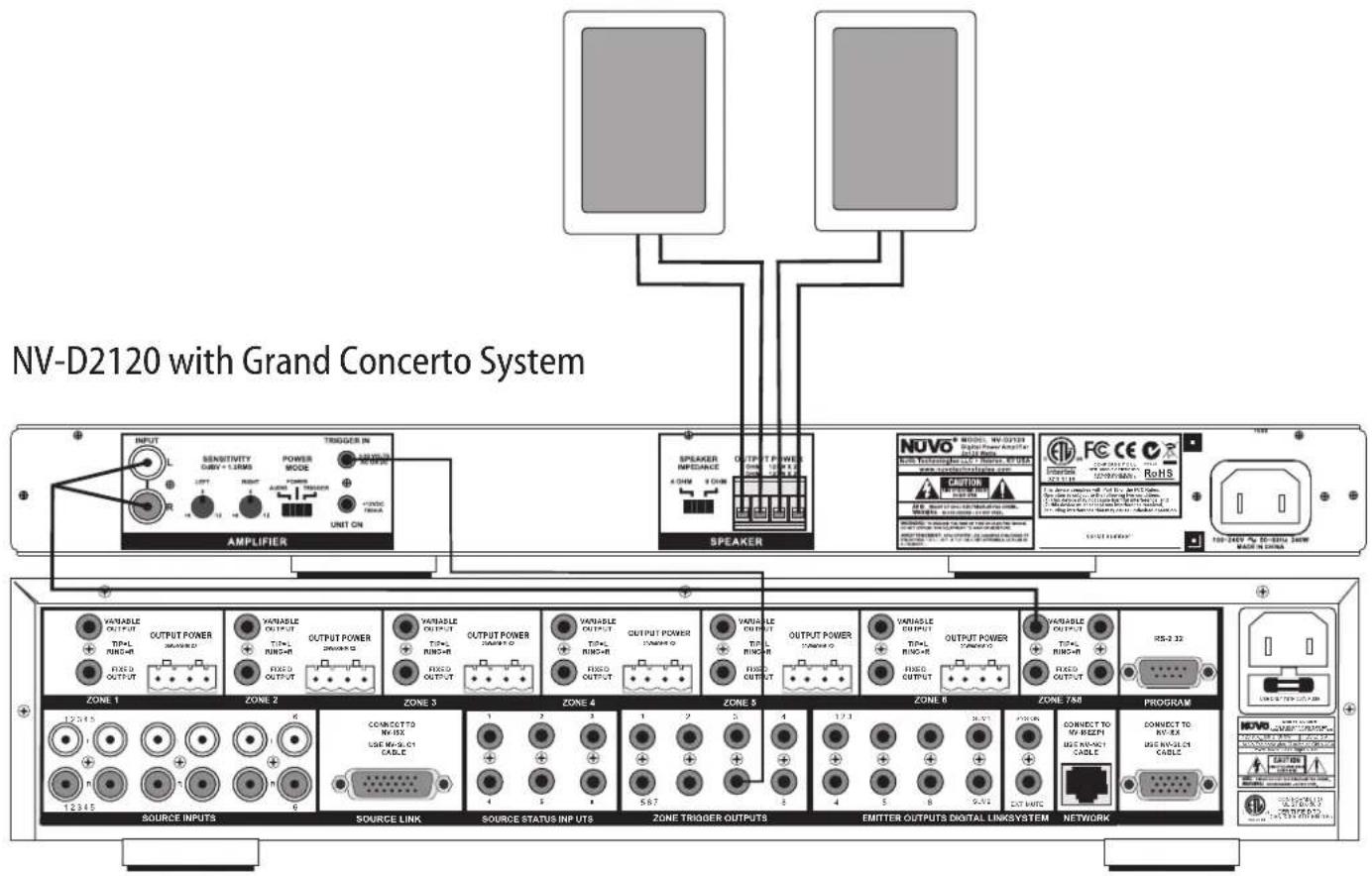
text_image
NV-D2120 with Grand Concerto System AMPLIFIER Sensitivity ABBV + 1.3MHz UNIT ON OUTPUT POWER POWER MODE UNIT ON Speaker OUTPUT POWER POWER UNIT ON NOVO MODEL NAME Digital Power Amplifier CAUTION ROHS 100-240V DC-Bias Zone WATER IN CHINA ZONE 1 ZONE 2 ZONE 3 ZONE 4 ZONE 5 ZONE 6 ZONE 7A0 PROGRAM SOURCE INPUTS SOURCE LINK SOURCE STATUS INPUTS ZONE TRIGGER OUTPUTS EMITTER OUTPUTS DIGITAL LINKSYSTEM NETWORK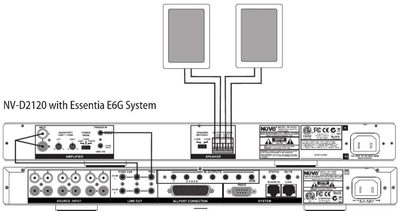
text_image
NV-D2120 with Essentia E6G System INPUT SENSITIVITY GAV + 1.0WNS POWER MODE UNIT ON AMPLIFIER SPEAKER INFOCARD 4 WINS 2 CHIN OUTPUT POWER 500 V 100 V Speaker NUVO MODE W-0323 Digital Power Amplifier Power Transmitter LCL - High Voltage Anode RoHS NUTR LUXOR SOURCE INPUT LINE OUT ALLPORT CONNECTION SYSTEM FIXED VAR TRIGS IR OUTPUTS STATUS MUTE ZONE 1 2 3 4 5 6 SDM NuVoN et LINK NUVO® SPECIAL RF-0323 1 2 3 4 5 6 7 8 9 10 11 12 13 14 15 16 17 18 19 20 21 22 23 24 25 26 27 28 29 30 31 32 33 34 35 36 37 38 39 40 41 42 43 44 45 46 47 48 49 50 51 52 53 54 55 56 57 58 59 60 61 62 63 64 65 66 67 68 69 70 71 72 73 74 75 76 77 78 79 80 ALLPORT CONNECTION RB232I. Audio Source Inputs
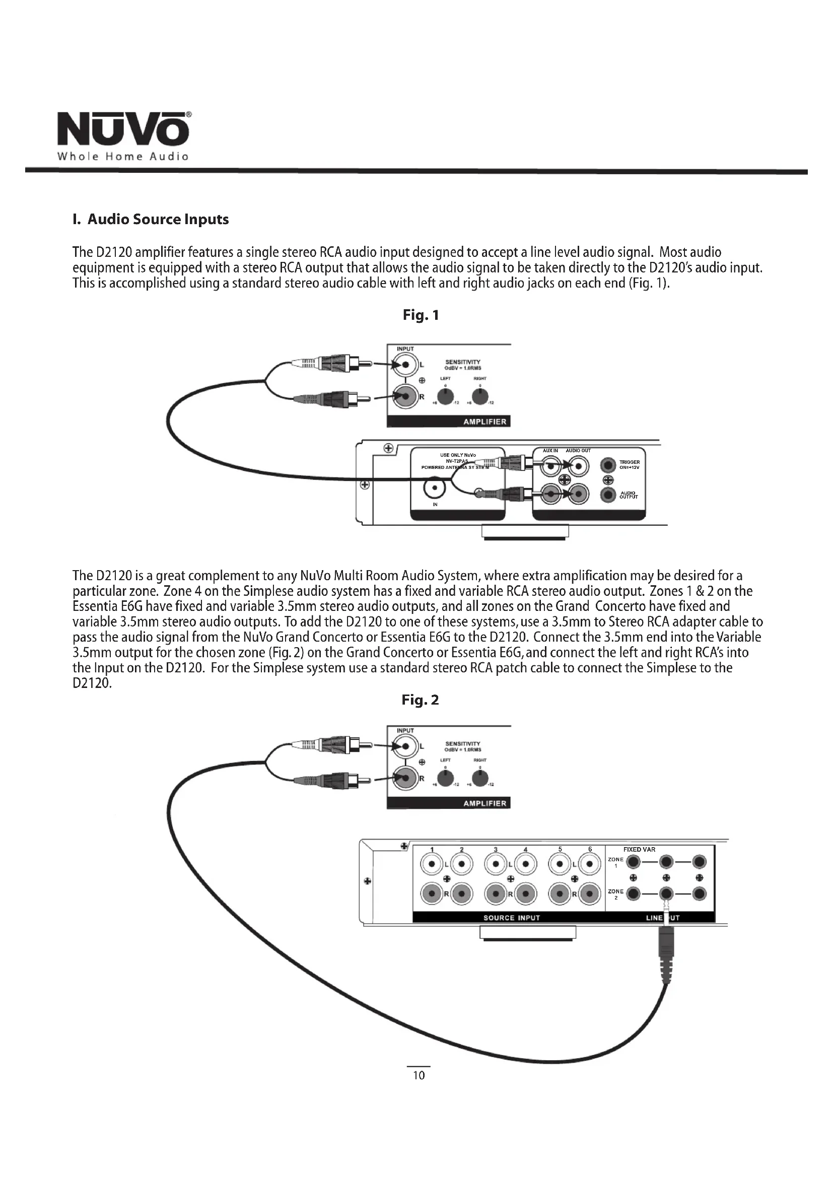
The D2120 amplifier features a single stereo RCA audio input designed to accept a line level audio signal. Most audio equipment is equipped with a stereo RCA output that allows the audio signal to be taken directly to the D2120's audio input. This is accomplished using a standard stereo audio cable with left and right audio jacks on each end (Fig. 1).
Fig. 1
text_image
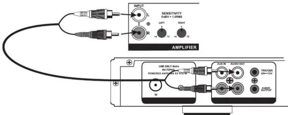
INPUT L SENSITIVITY O=BY = 1.0RMS R LEFT 0 -12 RIGHT +6 -12 AMPLIFIER USE ONLY NoNo NV-T2PAS POWERED ANTENZA SY STEIN AUX IN AUDIO OUT TRIGGER ON+12V AUDIO OUTPUTThe D2120 is a great complement to any NuVo Multi Room Audio System, where extra amplification may be desired for a particular zone. Zone 4 on the Simplese audio system has a fixed and variable RCA stereo audio output. Zones 1 & 2 on the Essentia E6G have fixed and variable 3.5mm stereo audio outputs, and all zones on the Grand Concerto have fixed and variable 3.5mm stereo audio outputs. To add the D2120 to one of these systems, use a 3.5mm to Stereo RCA adapter cable to pass the audio signal from the NuVo Grand Concerto or Essentia E6G to the D2120. Connect the 3.5mm end into the Variable 3.5mm output for the chosen zone (Fig. 2) on the Grand Concerto or Essentia E6G, and connect the left and right RCA's into the Input on the D2120. For the Simplese system use a standard stereo RCA patch cable to connect the Simplese to the D2120.
Fig. 2
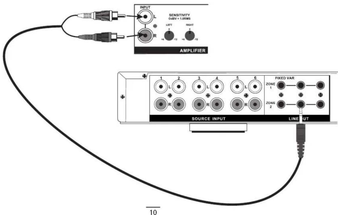
text_image
SENSITIVITY OdBV = 1.0RMS INPUT L R LEFT 0 -12 RIGHT 0 -12 AMPLIFIER 1 2 3 4 5 6 FIXED VAR ZONE 1 R R R ZONE 2 SOURCE INPUT LINEUT 10II. Audio Sensitivity Control
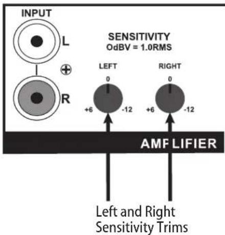
The D2120 allows the flexibility of controlling the left and right channel gains for the incoming audio signal. The sensitivity allows a control of -12 dB up to +6 dB, and is an excellent tool for maximizing the full output potential of your source equipment (Fig. 3).
Fig. 3
text_image
INPUT L R SENSITIVITY OdBV = 1.0RMS LEFT 0 -12 RIGHT 0 +6 -12 AMF LIFIER Left and Right Sensitivity TrimsTo best utilize this feature, set the volume for the source at its fullest output level. Then adjust the left and right sensitivity trims on the amplifier to allow the fullest possible output from the speakers without distortion.
+6 or a counter-clockwise turn is used to reduce the gain. This would be the preferred setting for a distributed audio system with variable preamp line outputs, such as any of the NuVo systems. Reducing the gain can also be useful for limiting the maximum power going to the speakers.
O or straight vertically is the factory default. This is the preferred setting for an audio signal from a preamp, such as a distributed audio system with a fixed preamp line output, or the audio output of a music server or CD player.
-12 or a clockwise turn is a high gain position. This is typically used when the incoming audio signal is weak, such as a portable CD player or iPod.
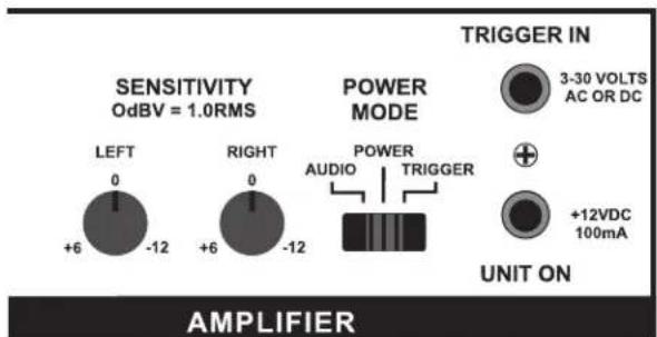
III. Power Mode
The D2120 provides three basic methods for supplying power to the amplifier. This can be accomplished by simply pushing the Power button on the front of the unit, by sensing an incoming audio signal, or by supplying a 3-30 volt AC or DC current. The Power Mode switch on the back of the amplifier (Fig. 4) sets the amplifier to respond to any of the three options.
Fig. 4
text_image
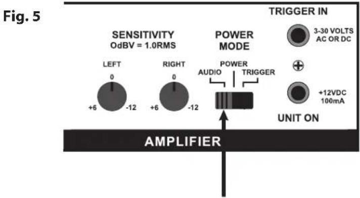
SENSITIVITY OdBV = 1.0RMS POWER MODE TRIGGER IN 3-30 VOLTS AC OR DC UNIT ON AMPLIFIERSetting the power mode switch to the left in the Audio mode (Fig. 5) sets the amplifier to respond to the presence of an audio signal. If you are triggering the amplifier in this way, you should expect a slight delay before it turns on.
When the audio signal is removed the amplifier will remain on for approximately three minutes after the incoming audio signal has ended before the unit turns off. This will prevent the unit from inadvertently turning off when the audio signal is very low or stops temporarily.
text_image
Fig. 5 SENSITIVITY OdBV = 1.0RMS POWER MODE TRIGGER IN 3-30 VOLTS AC OR DC LEFT 0 +6 -12 RIGHT 0 +6 -12 AUDIO TRIGGER +12VDC 100mA UNIT ON AMPLIFIERWhen setting the power mode switch to the center (Fig.6) the amplifier will turn on or off only when the Power button on the front of the amplifier is pressed.

text_image
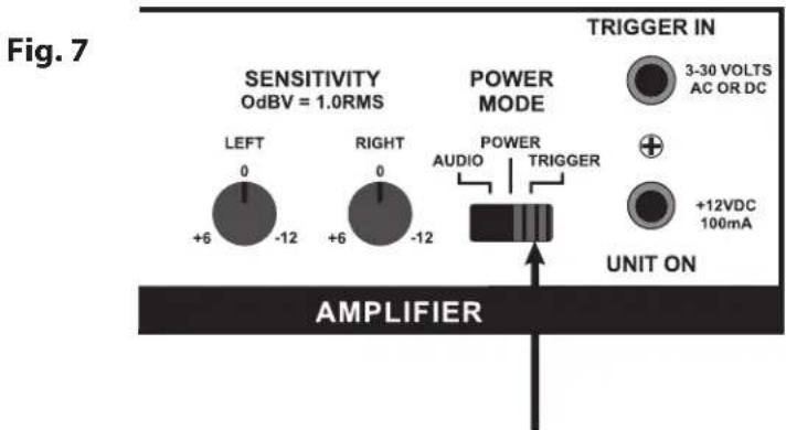
Fig. 6 SENSITIVITY OdBV = 1.0RMS POWER MODE TRIGGER IN 3-30 VOLTS AC OR DC LEFT 0 +6 -12 RIGHT 0 +6 -12 AUDIO TRIGGER +12VDC 100mA UNIT ON AMPLIFIERSetting the power mode switch to the right (Fig.7) sets the amplifier to respond to an incoming voltage. This voltage can be AC or DC and anything from 3-30 volts. This is very useful in conjunction with a multiroom audio system or preamp that has a voltage trigger output. In this mode the D2120 will turn on or off with the source equipment.
text_image
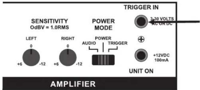
Fig. 7 SENSITIVITY OdBV = 1.0RMS POWER MODE TRIGGER IN 3-30 VOLTS AC OR DC LEFT 0 +6 -12 RIGHT 0 +6 -12 AUDIO TRIGGER +12VDC 100mA UNIT ON AMPLIFIERIV. Trigger In
This input (Fig. 8) is designed for a mono 1/8" plug to accept a trigger voltage coming in from an external source.
Any voltage ranging from 3 to 30 volts, AC or DC, will cause the amplifier to turn on when the Power switch is in the Trigger mode.
Fig. 8
text_image
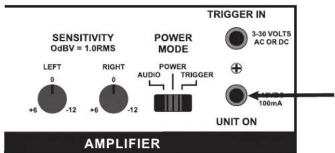
SENSITIVITY OdBV = 1.0RMS POWER MODE TRIGGER IN 3-30 VOLTS AC OR DC LEFT 0 +6 -12 RIGHT 0 +6 -12 POWER AUDIO TRIGGER +12VDC 100mA UNIT ON AMPLIFIERV. Unit On
This output (Fig. 9) provides a constant 12 volts DC when the amplifier is powered on. This is useful for powering on external equipment with the D2120.
Fig. 9
text_image
SENSITIVITY OdBV = 1.0RMS POWER MODE TRIGGER IN 3-30 VOLTS AC OR DC UNIT ON AMPLIFIERVI. Speaker Impedance
This switch (Fig. 10) allows for the adjusting of the impedance of the amplifier. By default the amplifier will be set at 8 ohms. This is fine is you are powering a pair of 8 ohm speakers, or a single stereo speaker rated at 8 ohms. In installations where three or more 8 ohm speakers will be used, or a pair of 4 ohm speakers are being utilized, the impedance of the amplifier should be set to 4 ohms. The power of the output will remain at 120 watts per channel.
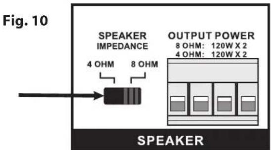
text_image
Fig. 10 SPEAKER IMPEDANCE 4 OHM 8 OHM OUTPUT POWER 8 OHM: 120W X 2 4 OHM: 120W X 2 SPEAKERVII. Speaker Outputs
The D2120 provides 120 watts of power per channel at four or eight ohms. It uses a modular plug (Fig. 11) that will accept up to 14 gauge, 4 conductor speaker wire. Stranded 4 conductor 16 gauge speaker wire is recommended.
Fig. 11
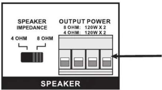
text_image
SPEAKER IMPEDANCE 4 OHM 8 OHM OUTPUT POWER 8 OHM: 120W X 2 4 OHM: 120W X 2 SPEAKERThe NV-D2120 amplifier is designed to run at a maximum load of 4 ohms. Prolonged operation at less than 4 ohms could cause the amplifier to overheat and damage its internal components. Overheating the amplifier due to an excessive load will void the warranty.
Digital Power Amplifier Specifications
Number of Channels
Power Output
| Continuous Average Output Power | 2 x 120W |
| Two channels driven 20-20kHz @1% THD | |
| Rated Distortion (1/2 power) | 0.02% |
| Rated Impedance | Switch Selectable 4 or 8 Ohms |
| Damping Factor | 50+ |
| Frequency Response (20-20kHz) | ±1 dB |
Power-On Modes
Audio
Power
Trigger
System
| Trigger Input | 3-30 V AC or DC |
| Unit On Output | +12VDC @100mA |
Source Inputs
| Input Impedance 22k ohm | |
| Input Sensitivity for rated power | .3-2V RMS |
| Input Overload 2.4V RMS | |
Power Requirements
| Power Supply | 100-240VAC 50/60Hz |
| Power Consumption both channels at maximum available output | 340W |
| Power Consumption average operating conditions | 50W |
| Power Consumption no signal | 12W |
| Standby Power Consumption | 0.35W |
CE EMC
CE LVD
USA FCC
ETL
Canada Safety Listing (CAN/CSA E60065.00)
Australia C-Tick
ENERGY STAR®
Physical Specifications
| Unit Size Millimeters | 44 H x 430 W x 250 D |
| Unit Size Inches | 1 3/4 H x 17 W x 9 7/8 D |
| Shipping Size Millimeters | 205 H x 515 W x 343 D |
| Shipping Size Inches | 8 H x 20 1/4 W x 13 1/2 D |
| Unit Weight Kilograms | 3.0 |
| Unit Weight Pounds | 6.6 |
| Shipping Weight Kilograms | 4.8 |
| Shipping Weight Pounds | 10.5 |
NuVo reserves the right to change specifications without notice.