
WA40 - Receiver NUVO - Free user manual and instructions
Find the device manual for free WA40 NUVO in PDF.


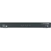
| Product Type | Multi-Zone Audio Receiver |
| Brand | NUVO |
| Model | WA40 |
| Dimensions (W x H x D) | 17.0 x 3.5 x 12.0 inches (43.2 x 8.9 x 30.5 cm) |
| Weight | 12.5 lbs (5.7 kg) |
| Power Supply | 120V AC, 60Hz (US), 230V AC, 50Hz (EU) |
| Power Consumption | 200W (max), <0.5W (standby) |
| Output Power | 40 watts per channel (5 channels) |
| Number of Zones | 4 independent zones |
| Supported Audio Sources | Bluetooth, FM/AM tuner, optical/coaxial digital, analog RCA, USB |
| Audio Inputs | 3x analog RCA, 2x optical, 1x coaxial, 1x USB |
| Audio Outputs | 4x speaker outputs (per zone), 1x subwoofer pre-out |
| Control Options | Front panel buttons, IR remote, NUVO app (iOS/Android) |
| Mounting | 19-inch rack mountable (brackets included) |
| Color | Black |
| Material | Aluminum front panel, steel chassis |
| Certifications | FCC, CE, RoHS |
| Warranty | 2 years limited |
| Cleaning Instructions | Wipe with dry soft cloth; avoid liquids |
| Safety | Do not expose to moisture; use grounded outlet; disconnect during storms |
| Repairability | Spare parts available through authorized service centers |
Frequently Asked Questions - WA40 NUVO
User questions about WA40 NUVO
0 question about this device. Answer the ones you know or ask your own.
Ask a new question about this device
Download the instructions for your Receiver in PDF format for free! Find your manual WA40 - NUVO and take your electronic device back in hand. On this page are published all the documents necessary for the use of your device. WA40 by NUVO.
USER MANUAL WA40 NUVO
natural_image
Exterior view of three white acoustic speakers with control panel buttons (no text or symbols on main objects)NV-WA40W
Installation and User Guide
Introduction
The NV-WA40W-AMP is a versatile 40-watt in wall zone amplifier perfectly suited to a variety of tasks. Its design allows two line level sources to be permanently wired into the back panel as a switchable input A or B, and two optional front panel stereo mini inputs allows any local source to be easily amplified to dedicated speakers.
The WA40W-AMP fits in educational classroom settings, doctors' offices, hotels, and many other installations where a compact, inexpensive amplifier solution is needed.
Table of Contents
Wiring Diagram ...... Page 2
NV-WA40W-AMP Front Panel Features ...... Page 3
NV-WA40W-AMP Back Panel Features ...... Page 4
NV-WA40W-RC Remote Control...... Page 5
Installing the NV-WA40W-AMP Page 6
The NV-WA40W-SPK Speakers ...... Page 9
NV-WA40W Specifications ...... Page 10
NV-WA40W Line Drawing ...... Page 11
NV-WA40W Wiring Diagram

flowchart
graph TD
    A["Power Supply"] --> B["Line 1"]
    B --> C["Line 2"]
    C --> D["Line 3"]
    D --> E["Line 4"]
    E --> F["Line 5"]
    F --> G["Line 6"]
    G --> H["Line 7"]
    H --> I["Line 8"]
    I --> J["Line 9"]
    J --> K["Line 10"]
    K --> L["Line 11"]
    L --> M["Line 12"]
    M --> N["Line 13"]
    N --> O["Line 14"]
    O --> P["Line 15"]
    P --> Q["Line 16"]
    Q --> R["Line 17"]
    R --> S["Line 18"]
    S --> T["Line 19"]
    T --> U["Line 20"]
    U --> V["Line 21"]
    V --> W["Line 22"]
    W --> X["Line 23"]
    X --> Y["Line 24"]
    Y --> Z["Line 25"]
    Z --> AA["Line 26"]
    AA --> AB["Line 27"]
    AB --> AC["Line 28"]
    AC --> AD["Line 29"]
    AD --> AE["Line 30"]
    AE --> AF["Line 31"]
    AF --> AG["Line 32"]
    AG --> AH["Line 33"]
    AH --> AI["Line 34"]
    AI --> AJ["Line 35"]
    AJ --> AK["Line 36"]
    AK --> AL["Line 37"]
    AL --> AM["Line 38"]
    AM --> AN["Line 39"]
    AN --> AO["Line 40"]
    AO --> AP["Line 41"]
    AP --> AQ["Line 42"]
    AQ --> AR["Line 43"]
    AR --> AS["Line 44"]
    AS --> AT["Line 45"]
    AT --> AU["Line 46"]
    AU --> AV["Line 47"]
    AV --> AW["Line 48"]
    AW --> AX["Line 49"]
    AX --> AY["Line 50"]
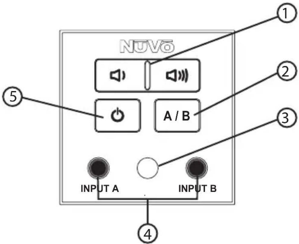
NV-WA40W-AMP Front Panel features
- Volume: These buttons increase and decrease the signal output of the amplifier.
- A/B: This button toggles between the A and B hardwired inputs on the back panel or the individual front panel inputs. Use of the front panel inputs will override those on the back panel.
- IR Sensor: The WA40W-AMP is capable of receiving IR (Infrared) light signals from the NuVo wireless remote control. This enables the power, volume and A/B source selection to be done wirelessly.
- Audio Inputs: Two stereo inputs are available for front panel use with any device that provides a stereo line level signal.
- Power: This button turns the amplifier on and off as a toggle function.

NV-WA40W-AMP Back Panel Features
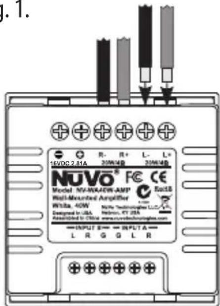
- DC Input: This 16V DC, 2.81A input connects to the included power supply. Once connected, the power supply can plug into any AC power source.
- Speaker Output: The speaker output section terminates with standard audio wire. This provides the amplified audio signal to the attached speakers. The NV-WA40W-AMP is designed for a pair of 4-ohm speakers or a single stereo speaker rated at 4-ohms per channel.
- Audio Inputs A and B: These inputs allow up to two line level sources to be permanently hardwired into the back panel. Selection for source playback is made through from the front panel A/B button or the wireless remote control. The inputs are automatically overridden when one of the front panel audio inputs is used.

NV-WA40W-RC Remote Control (sold separately)
- Volume: These buttons increase and decrease the signal output of the amplifier.
- A/B: This button toggles between the A and B hardwired inputs on the back panel or the individual front panel inputs. Use of the front panel inputs will override those on the back panel.
- Power: This button turns the amplifier on and off as a toggle function.
Installing the NV-WA40W-AMP
Step 1: Choose the desired location of the WA40W-AMP. It is designed to fit into a standard 35mm deep UK back box. The WA40W-AMP dimensions are a standard 50 x 50mm UK size, and has a screwless trim plate kit included in the package. Make the appropriate cutout for the mounting back box. The amplifier itself is compatible with standard 50 x 50mm wall plates. Note that a standard size Decora®* trim plate is available in regions where the standard Decora mounting box is installed, such as North America.
Step 2: Define the best location for the speakers that will be connected to the WA40W-AMP amplifier. These can be in wall, in ceiling, floor standing, or bookshelf speakers, but should not present less than an 4-ohm load to the amplifier. 16-gauge speaker wire, either two or four conductor, is recommended for this purpose. The wire should be routed to the cutout for the WA40W-AMP for termination into the back of the component, as shown in fig. 1.
Fig. 1
* Decora is a registered trade mark of the Leviton Corporation.
Step 3: Along with the speaker wire, route the power supply to the same cutout and terminate the positive and negative leads at the back of the WA40W-AMP, as shown in fig. 2.
Fig. 2

Step 4: Connect the optional back panel audio inputs. There are two hardwired audio inputs on the back of the WA40W-AMP. They are labeled Input A and Input B. Two individual audio sources can be wired to these inputs simultaneously. The actual source for playback is selected from the front Panel A/B button, or from the A/B button on the wireless remote control.
To make the termination, strip the left, right and ground leads on the input side of a stereo RCA or stereo mini, 3.5mm audio cable. Terminate those leads into the appropriate screw down terminals on the WA40W-AMP.
Step 5: When the desired inputs on the WA40W-AMP are complete, screw the mounting plate into the installed back box.
Step 6: Snap the WA40W-AMP into the installed mounting plate and install the screwless trim plate over the entire assembly.
The WA40W-AMP is now ready for operation. When it is turned on, the ON LED will light. Any incoming signal wired to the back panel will be amplified to the attached speakers. When an audio source is plugged into one of the front panel 3.5mm inputs, it will automatically override the back panel inputs.
The WA40W-SPK Speakers
The NV-WA40W package includes a pair of 0n-wall speakers. These are easily mounted to any wall using the included brackets, as shown in fig. 3.
Fig. 3

natural_image
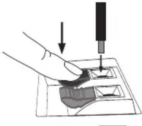
Technical line drawing of a mechanical device with wheels and adjustment knobs (no text or symbols)To properly terminate the speaker, strip about 5 to 6mm of insulation, exposing the inner copper wire. Press the desired speaker terminal and insert the stripped portion of the speaker wire, as shown in fig. 4. Be careful to terminate the positive and negative conductors the same at the speakers as you did at the WA40W-AMP amplifier.
Fig. 4
natural_image
Illustration of a hand using a screwdriver to press down a small object on a device (no text or symbols present)NV-WA40W-AMP
Power Amplifier Output
| Continuous Average Output Power | 40W (20W x 2) |
| Both channels | 1kHz / 1% THD |
| Rated Distortion ( 12 power) | 0.40% |
| Rated Impedance | 4 Ohms |
| Frequency Response (20-20kHz) | ±2 dB |
Source Input
| Front | 3.5mm Stereo Jack |
| Input Impedance | 20K Ohms |
| Input Sensitivity for Rated Power | 300mV RMS |
Back
| Variable Input | Screw Terminal |
| Input Impedance | 20K Ohms |
| Input Sensitivity for Rated Power | 300mV RMS |
| Fixed Input | Screw Terminal |
| Input Impedance | 20K Ohms |
| Input Sensitivity for Rated Power | 300mV RMS |
Power Requirements
| Power Supply | 16VDC |
| Power Consumption at maximum available output | 45W |
| Power Consumption with music (typical) | 10W |
| Power Consumption no signal | 2.1W |
| Power Consumption standby | 0.5W |
| Auto Shut-off Time | 20mins |
WA40W-AMP Approvals
| CE-EMC (EU), FCC (USA and Canada) |
Physical Specifications
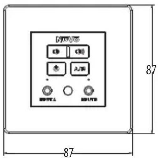
| Unit Size | 50mm x 50mm x 29mm |
| 1.97" x 1.97" x 1.14" | |
| Shipping Size | 424mm x 306mm x 395mm |
| 16.7" x 12" x 15.5" | |
| Unit Weight | 0.11 Kg / 0.24 lbs |
| Shipping Weight | 7.0 Kg / 15.4 lbs |
NV-WA40W-SPK Speaker
Electrical
| Power | 10 ~50W |
| Impedance | 4 Ohms |
| Physical Specifications | |
| Unit Size | 190mm x 160mm x 90mm7.5" x 6.3" x 3.54" |
| Shipping Size | 400mm x 350mm x 245mm15.75" x 13.78" x 9.65" |
NV-WA40W-RC Remote Control (sold separately)
Electrical
| IR Frequency | 38.7 kHz |
| Batteries | AAA x 2 |
Physical Specifications
| Unit Size | 110mm x 42mm x 14mm |
| 4.33" x 1.65" x 0.55" | |
| Shipping Size | 296mm x 245mm x 280mm |
| 11.65" x 9.65" x 11" |
NuVo reserves the right to change specifications without notice.

natural_image
Technical line drawing of a mechanical component with dimension标注 (no text or symbols)
NV-WA40W-AMP-UK


natural_image
Technical line drawing of a mechanical component with dimension标注 (no text or symbols)
NV-WA40W-AMP-DC
EC Declaration of Conformity
We: NuVo Technologies, LLC.
3015 Kustom Drive
Hebron, KY USA 41048

Declare that the Product model numbers: NVWA40W-UK/ NVWA40W-AMP-UK/NVWA40W-DC/NVWA40W-AMP-DC/NVWA40W-SPK/NVWA40W-RC
Power adaptor: NVWA40W-PS-UK/NVWA40W-PS-NA/NVWA40W-PS-EU/NVWA40W-PS-AU
to which this declaration relates is in conformity with the following standards:
EN55013: 2001+/A1: 2003+/A2: 2006: Limits and methods of measurement of radio disturbance characteristics of broadcast receivers and associated equipment.
En55020: 2007: Electromagnetic immunity of broadcast receivers and associated equipment.
EN 61000-3-2: 2006: Limits for harmonic current emissions (equipment input current <=16A per phase)
EN61000-3-3: 2008: Limitation of voltage fluctuations and flicker in low-voltage supply systems for equipment with rated current <=16A
Following the provisions of EU Council: EMC Directive (2004/108/EC)
Year CE mark affixed: 2011
We the undersigned, hereby declare that the equipment specified above conforms to the aforementioned directive(s).
Name of authorized person: Rick Kukulies
Chief Technical Officer Signature: Date: 11/23/11
NuVo Technologies, LLC.
3015 Kustom Drive
Hebron, KY USA 41048
FCC Compliance Statement
This equipment has been tested and found to comply with the limits for a Class B digital device, pursuant to Part 15 of the FCC Rules. These limits are designed to provide reasonable protection against harmful interference in a residential installation. This equipment generates, uses, and can radiate radio frequency energy and, if not installed and used in accordance with the instructions, it may cause harmful interference to radio communications. However, there is no guarantee that interference will not occur in a particular installation. If this equipment does cause harmful interference to radio or television reception, which can be determined by turning the equipment off and on, the user is encouraged to try to correct the interference by one or more of the following measures:
- Reorient or relocate the receiving antenna.
- Increase the separation between the equipment and receiver.
- Connect the equipment into an outlet on a circuit different from that to which the receiver is connected.
- Consult the dealer or an experienced radio/TV technician for assistance.
This device complies with Part 15 of the FCC Rules. Operation is subject to the following two conditions: (1) This device may not cause harmful interference, and (2) this device must accept any interference received, including interference that may cause undesired operation.
Canadian Compliance Statement
This device complies with Industry Canada license-exempt RSS standard(s). Operation is subject to the following two conditions: (1) this device may not cause interference, and (2) this device must accept any interference, including interference that may cause undesired operation of the device.
Industry Canada Statement
As an ENERGY STAR partner, NuVo has determined that product meets the ENERGY STAR guidelines for energy efficiency. The ENERGY STAR program is a partnership with electronic equipment manufacturers to promote energy-efficient products.
For more information about ENERGY STAR, visit: www.energystar.gov
- NV-WA40W
- Installation and User Guide
- Introduction
- Table of Contents
- NV-WA40W-AMP Front Panel features
- NV-WA40W-AMP Back Panel Features
- NV-WA40W-RC Remote Control (sold separately)
- Installing the NV-WA40W-AMP
- The WA40W-SPK Speakers
- EC Declaration of Conformity
- FCC Compliance Statement
- Canadian Compliance Statement
- Industry Canada Statement
Brand : NUVO
Model : WA40
Category : Receiver