
790096 - Above-ground pool GRE - Free user manual and instructions
Find the device manual for free 790096 GRE in PDF.
| Product type | Above-ground pool |
| Brand | Gre |
| Model | 790096 |
| Dimensions (L x W x H) | 551 x 351 x 119 cm |
| Shape | Oval |
| Structure material | Autoclave-treated Scots pine class IV |
| Liner material | Reinforced PVC |
| Wood structure warranty | 10 years against rot and insects |
| Liner warranty | 2 years on welds and waterproofing |
| Filtration system | Sand filter with multiport valve (4 or 6 positions) |
| Pump | Electric 220 V, 30 mA differential protection |
| Flow rate | Approximately 6-8 m³/h (estimate) |
| Sand tank capacity | 25 kg of calibrated sand |
| Minimum electrical safety distance | 3.50 m from pool edge |
| Number of people required for assembly | 2 people minimum |
| Estimated assembly time | 2 days (excluding earthwork and filling) |
| Water volume | Approximately 19.5 m³ |
| Included equipment | Skimmer, return nozzle, stainless steel ladder, wooden coping |
| Recommended safety devices | Fence, alarm, safety cover |
| Spare parts available | 2 years from invoice date |
| Liner maintenance | Regular cleaning with non-abrasive products |
| Water treatment | Chlorine, bromine or oxygen; pH between 7.2 and 7.4 |
| Winterizing | Cleaning, winterizing treatment, protective cover |
Frequently Asked Questions - 790096 GRE
User questions about 790096 GRE
0 question about this device. Answer the ones you know or ask your own.
Ask a new question about this device
Download the instructions for your Above-ground pool in PDF format for free! Find your manual 790096 - GRE and take your electronic device back in hand. On this page are published all the documents necessary for the use of your device. 790096 by GRE.
USER MANUAL 790096 GRE
natural_image
Isometric illustration of a rectangular building with a blue roof and ladder, no text or symbols present- Important/ Importante/ Important/ Wichtig/ Importante/ Belangrijk/ Importante 4
● Guarantee/ Garantía/ Garantie/ Garantie/ Garanzia/ Garantie/ Garantia 12 - Learn about the wood/ Conozca la madera/ Mieux connîatre le bois/ Das holz besser kennenlernen/ 40 Conosci il legno/ Wat u moet weten over hout/ Conheça a madeira
- Installation drawing / Plano de instalación / Plan d'implantation / Aufstellplan / Piano di installazione / Installatieplan / Plano de instalação 42
- Previsions / Previsiones / A prévoir / Vorausplanung / Precauzioni / Rekening houden met / Previsões 44
- Components/ Componentes/ Elements/ Bestandteile componenti/ Onderdelen/ Componentes 46
● Preparing the land/ Preparación del terreno/ Préparation du terrain/ Geländevorbereitung/ Preparazione del terreno/ Voorbereiding van het terrein/ Preparação do terreno 47 - Boards + Protective ground blanket / Tablas + Manta protectora de fondo / Madriers + Feutre de fond / Erdarbeiten + Schutzdecke im untergrund / Tavole + Copertura di protezione del fondo / Planken + Beschermdeken bodem / Tábuas + Manta protetora de fundo 96
- Assembly of the structure / Montaje de la estructura / Assemblage de la structure / Zusammenbau des 98 Tragwerks / Montaggio della struttura / Montage van de constructie / Montagem da estrutura
- Wooden blocks, reinforcements and trimmings / Tacos, refuerzos y embellecedores / Consoles, renforts 102 et caches / Konsolen, Verstärkungen und Zierleisten / Tasselli, rinfortzi e coperture / Console, verstevigingen en sierlijsten / Blocos de madeira, reforços e embelezadores
- Wooden setpladder / Escalera de madera / Echelle bois / Holzterppe / Scala di legno / Houten trap / Escada de madeira 106
-
Protective wall blanket / Manta protectora de pared / Feutre de paroi / Schutzdecke an der Wand / Copertura di protezione della parte / Beschermdeken muur / Manta protetora de parede 110
-
Fixing of the skimmer joint / Fijación de la junta skimmer / Fixation du joint de skimmer / Befestigung der 112 Dichtung des Skimmers / Fissaggio del giunto dello skimmer / Vastzetten van de skimmerverbinding / Fixação da junta do skimmer
- Installation of the liner hooking profile/ Colocación de los perfiles de enganche del liner/ Positionnement des baguettes d'accroche de liner/ Positionierung der einhakprofile des liners/ Posizionamento dei profili di aggancio del liner/ Plaatsing van de klemprofielen voor inhangen van de liner/ Coloção dos perfis de engate do liner 114
- Installation of the liner / Colocación del liner / Mise en place du liner / Positionierung des Liners / Posizionamiento del liner / Plaatsing van de liner / Colocação do liner 121
● Land-filling / Terraplenado / Remblaiement / Anschüttung / Terrapieno / Grond effenen / Aterro 125 - Positioning of the sealing pieces + Skimmer / Posicionamiento de las piezas de sellado + Skimmer / Positionnement des pièces à sceller + Skimmer / Positionierung der Versiegelungsteile + Skimmer / Posizionamento dei pezzi di saldatura + Skimmer / Plaatsing van de af te dichten onderdelen + Skimmer / Posicionamento das peças de selagem + Skimmer
- Filter / Filtración / Filtration / Filtration / Filtrazione / Filtering / Filtração 142
- Sand Filter / Filtro de arena / Filtre à sable / Sandfilter / Filtro per la sabbia / Zandfilter / Filtro de areia 144
- Edges / Playas / Margelles / Ränder / Bordi / Randen / Bordos 148
- Fixing of the stainless steel ladder / Fijación de la escalera inoxidable / Fixation de l'echelle inox / Befestigung einer Treppe aus rostfreiem Material / Fissaggio della scala di acciaio inossidabile / Bevestiging van de rvs-ladder / Fixação da escada inoxidável 152
- Putting into service + Maintenance and treatment + Safety suggestions / Puesta en servicio + Mantenimiento y servicio + Consejos de seguridad / Mise en service + Entretien et traitement + Conseils de sécurité / Inbetriebnahme + Instandhaltung und Pflege + Sicherheitsinweise / Messa in servizio + Manutenzione e trattamento + Consigli per la sicurezza / Ingebruikname + Onderhoud en behandeling + Veiligheidsinformatie / Colocação em serviço + Manutenção e tratamento + Informação de segurança
- Normal maintenance + Wintering / Mantenimiento habitual + Ivernaje / Entretien courant + Hivernage / 168 Übliche Instandhaltung + Überwinterung / Manutenzione ordinaria + Invernaggio / Routineonderhoud + Winterklaar maken / Manutenção habitual + Hibernação
EN IMPORTANT
ES IMPORTANTE
FR IMPORTANT
DE WICHTIG
IT IMPORTANTE
NL BELANGRIJK
PT IMPORTANTE

COMPULSORY·OBLIGATORIO·IMPÉRATIF·OBLIGATORISC ·OBBLIGATORIO ·VERPLICHT ·OBRIGATÓRIO
EN Make sure you keep this sheet from the manufacturer. It will be necessary to resolve any problem that may arise in the future. Without this sheet, the guarantee of the pool may be void.
ES Acuérdese de guardar la hoja del fabricante. Será necesaria para resolver cualquier problema que pueda surgir en el futuro. Sin esa hoja, la garantía de la piscina puede perderse.
FF Conservez la fiche du fabricant. Vous en aurez besoin pour résoudre d'éventuels problèmes à l'avenir. Sans cette fiche, vous risquez de perdre la garantie de votre piscine.
DE Bitte bewahren Sie das Herstellerblatt auf, da es zur Behebung eventueller künftiger Probleme erforderlich ist. Ohne das Herstellerblatt kann die Garantie für das Becken verfallen.
IT Conservare il foglio delle istruzioni fornito dal produttore in quanto potrebbe risultare fondamentale per risolvere eventuali problematiche future. In assenza di questo foglio la garanzia perderà di validità.
NL Zorg ervoor dat u het blad van de fabrikant goed bewaard. U zult het in de toekomst nodig hebben voor het oplossen van mogelijke problemen. Zonder dit blad, kan de garantie op het zwembad komen te vervallen.
PT Lembre-se de guardar a folha do fabricante. Será necessária para resolver qualquer problema que puder surgir no futuro. Sem essa folha, a garantia da piscina pode ser perdida.

Preparation: Date: 1/2018
| PISCINE CANELLE | 790087 MAG | |
| Piscine Bois RL 551x351 H119 All - 8 pans | 790087D LD |
natural_image
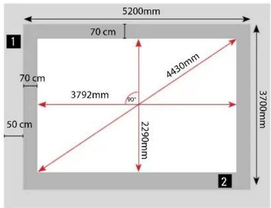
Pure electrical circuit lines without any symbolsEN The diagonal dimensions of the pool SHOULD BE verified. This is necessary to avoid problems later. Revise them several times until obtaining the dimensions indicated on the drawings.
ES Es IMPRESCINDIBLE verificar las medidas de las diagonales de las piscinas. De esta manera se evitarán problemas posteriormente. Revisar esto varias veces hasta obtener las medidas indicadas en los planos.
FR Il est INDISPENSABLE de vérifier les mesures diagonales des piscines. De cette façon, d'éventuels problèmes ultérieurs seront évités. Réviser cela plusieurs fois jusqu'à obtenir les mesures indiquées sur les plans.
DE Um spätere Probleme zu vermeiden, müssen die Diagonalmaße der Becken UNBEDINGT überprüft werden. Bitte solange wiederholt prüfen, bis die in den Zeichungen angegebenen Maße erzielt wurden.
IT E' FONDAMENTALE verificare le misure delle diagonali delle piscine, onde evitare problemi in seguito. Controllarle più volte al fine di ottenere le misure indicate negli schemi.
NL Het is van ESSENTIEEL belang dat u de maten van de zwembaddiagonalen controleert. Op deze manier voorkomt u latere problemen. Controleer dit enkele keren totdat u zeker weet dat u de juiste maten heeft zoals aangegeven op de plannen.
PT É IMPRESCINDÍVEL verificar as dimensões das diagonais das piscinas. Desta maneira, serão evitados problemas futuros. Rever isto várias vezes até obter as dimensões indicadas nos planos.
natural_image
3D rendering of a wooden mechanical part with cutouts and mounting holes (no text or symbols)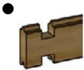
natural_image
3D rendered mechanical part with a black dot above it (no text or symbols)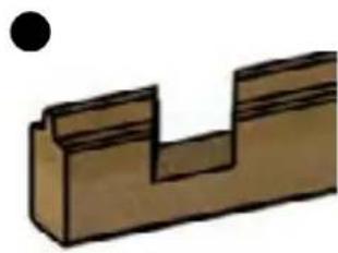
natural_image
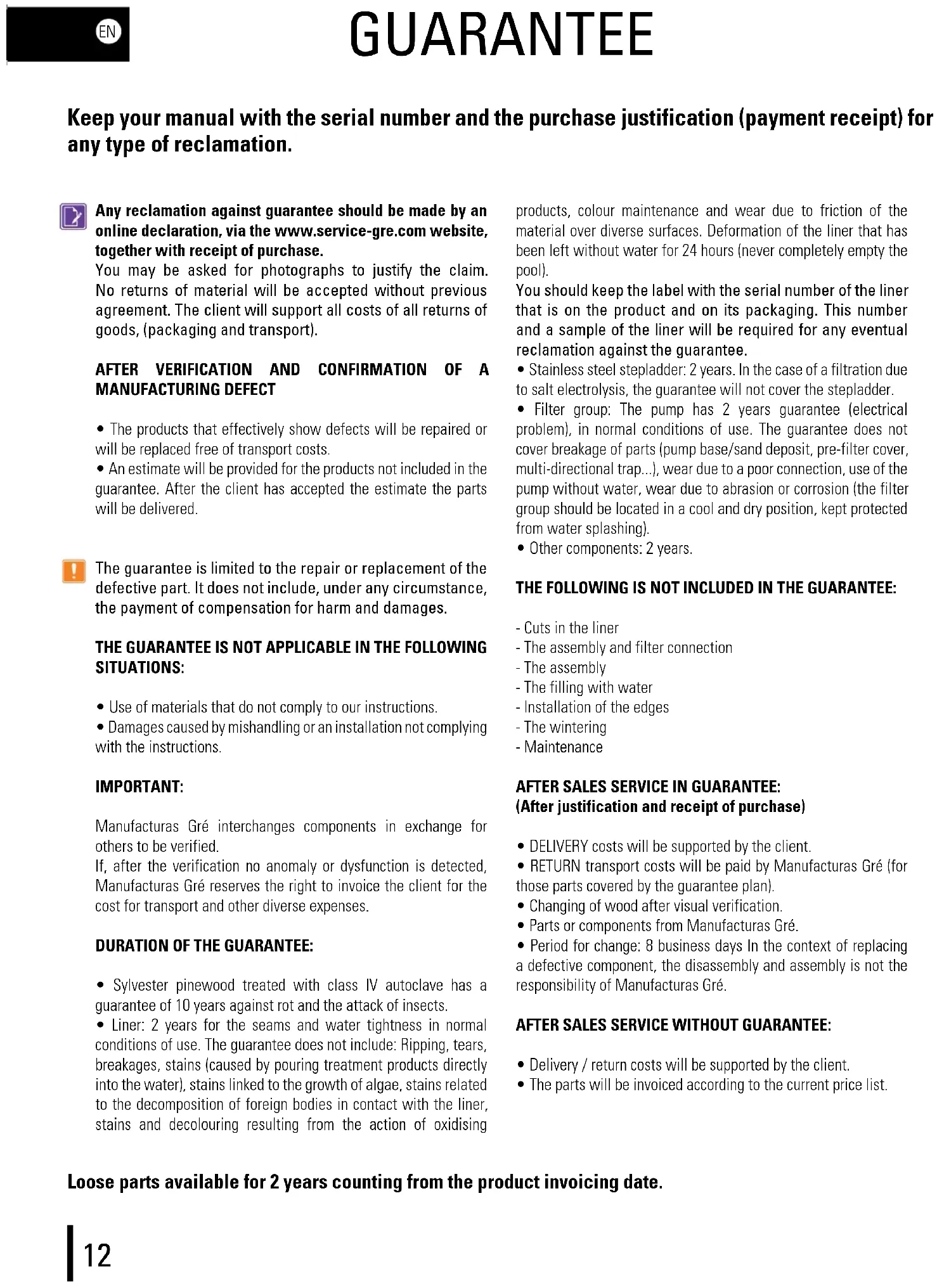
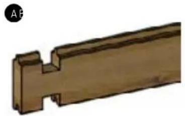
Simple 3D diagram of a stepped block with a black dot above it (no text or symbols)EN In the case of breakages and/or deformations of the wood, make a complete inventory of the state of the pieces before requesting them from after-sales. This way, the pieces will all arrive in the same delivery
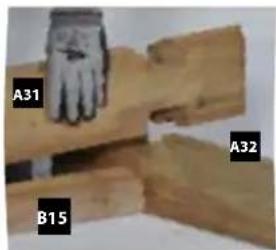
For the assembly, the tongue of the strip should always be facing upwards, (for pools with tongue and groove system). (A)
In the first line of strips, (at the base of the pool) it is normal that some strips have a groove at the bottom part and others do not have one, with a flat base (medium width strips). (B-C)
During the winter, metal finishes of the beaches can oxidise. You are responsible for the maintenance of these parts. If you use a winter cover, make sure it has correct ventilation.
Locate the maintenance section in the manual of your stainless-steel ladder (in the case this is included with the pool)
other
| Dimension | Value | | --------- | ----- | | Total Height | 4000 | | Vertical Width | 2500 | | Horizontal Height | 2290 | | Vertical Width | 2382 | | Horizontal Height | 4430 | | Vertical Width | 3884 | | Horizontal Height | 3792 | The chart contains multiple labeled dimensions (e.g., '4000', '2500') but contains specific numerical values for the layout.
Wooden blocks
Tacos de madera
Consoles
Konsolen
Tasselli
Console
Blocos de madeira

Big reinforcements
Refuerzos grandes
Grands renforts
Große Verstärkungen
Rinforzi grandi
Carefully read this information and keep it for later consultations
Congratulations on your choice. The model you have chosen has been especially designed for simple and rapid installation, but some precaution is necessary for the good use of your pool. Before starting with the installation and assembly of your pool, consider the current local regulation about on ground and in ground pools.
The use of the pool kit includes respecting the safety instructions described in the maintenance manual and instructions for use. If the safety regulations are not respected serious damage for your health and specially for that of children may occur. Carefully read this manual and pay attention to the illustrations before starting to assemble the pool. In the case that the assembly does not follow this manual the guarantee may be rejected in the case of failure.
The information appearing in this installation manual shows exactly how it should be done. Nevertheless, the illustrations in the same are to explain the assembly process. Contractual elements will not be considered regarding the shape, the colours and the aspects shown in the illustrations. Manufacturas Gré in its commitment to ongoing improvement of their products, reserves the right to modify at any time and without previous warning the features, the technical details, the standardized equipment and the options of its products.
ES ¡ATENCIÓN!
Keep your manual with the serial number and the purchase justification (payment receipt) for any type of reclamation.

Any reclamation against guarantee should be made by an online declaration, via the www.service-gre.com website, together with receipt of purchase.
You may be asked for photographs to justify the claim. No returns of material will be accepted without previous agreement. The client will support all costs of all returns of goods, (packaging and transport).
AFTER VERIFICATION AND CONFIRMATION OF A MANUFACTURING DEFECT
- The products that effectively show defects will be repaired or will be replaced free of transport costs.
- An estimate will be provided for the products not included in the guarantee. After the client has accepted the estimate the parts will be delivered.

The guarantee is limited to the repair or replacement of the defective part. It does not include, under any circumstance, the payment of compensation for harm and damages.
THE GUARANTEE IS NOT APPLICABLE IN THE FOLLOWING SITUATIONS:
- Use of materials that do not comply to our instructions.
- Damages caused by mishandling or an installation not complying with the instructions.
IMPORTANT:
Manufacturas Gré interchanges components in exchange for others to be verified.
If, after the verification no anomaly or dysfunction is detected, Manufacturas Gré reserves the right to invoice the client for the cost for transport and other diverse expenses.
DURATION OF THE GUARANTEE:
- Sylvester pinewood treated with class IV autoclave has a guarantee of 10 years against rot and the attack of insects.
- Liner: 2 years for the seams and water tightness in normal conditions of use. The guarantee does not include: Ripping, tears, breakages, stains (caused by pouring treatment products directly into the water), stains linked to the growth of algae, stains related to the decomposition of foreign bodies in contact with the liner, stains and decolouring resulting from the action of oxidising
products, colour maintenance and wear due to friction of the material over diverse surfaces. Deformation of the liner that has been left without water for 24 hours (never completely empty the pool).
You should keep the label with the serial number of the liner that is on the product and on its packaging. This number and a sample of the liner will be required for any eventual reclamation against the guarantee.
- Stainless steel stepladder: 2 years. In the case of a filtration due to salt electrolysis, the guarantee will not cover the stepladder.
- Filter group: The pump has 2 years guarantee (electrical problem), in normal conditions of use. The guarantee does not cover breakage of parts (pump base/sand deposit, pre-filter cover, multi-directional trap...), wear due to a poor connection, use of the pump without water, wear due to abrasion or corrosion (the filter group should be located in a cool and dry position, kept protected from water splashing).
- Other components: 2 years.
THE FOLLOWING IS NOT INCLUDED IN THE GUARANTEE:
- Cuts in the liner
- The assembly and filter connection
- The assembly
- The filling with water
- Installation of the edges
- The wintering
- Maintenance
AFTER SALES SERVICE IN GUARANTEE: (After justification and receipt of purchase)
- DELIVERY costs will be supported by the client.
- RETURN transport costs will be paid by Manufacturas Gré (for those parts covered by the guarantee plan).
- Changing of wood after visual verification.
- Parts or components from Manufacturas Gré.
- Period for change: 8 business days In the context of replacing a defective component, the disassembly and assembly is not the responsibility of Manufacturas Gré.
AFTER SALES SERVICE WITHOUT GUARANTEE:
- Delivery / return costs will be supported by the client.
- The parts will be invoiced according to the current price list.
Loose parts available for 2 years counting from the product invoicing date.
PROLOGUE
STORAGE PRECAUTIONS
While the pool is disassembled, it is sensitive to variations of temperature and humidity. Therefore, certain precautions should be taken for storage.
When you receive the packets, store the pieces of wood in horizontal position on a flat surface, shielding them from humidity and sunlight to avoid any risk of deformation.
ESSENTIAL:
- Do not store the wood in sunlight, to avoid excessive sags or cracks in the wood.
- Do not store the pool outside protected by a watertight cover, because the condensation emanating from the wood will make it even more humid and will subject to changes of shape.
COMPULSORY:
- Assemble the structure only once.
- Store the wood of your pool on a flat surface, shielding it from humidity and sunlight.
- Remove the protective film so the wood can «breathe».
DURATION OF THE INSTALLATION
The installation of this pool needs the intervention of at least two persons and takes two days (besides the preparation of the land and the filling).
BEFORE BUILDING YOUR POOL MAKE SURE
- You have the assistance of a qualified person for the electrical connections.
- There is sufficient water supply to fill the pool.
- That you have carefully read the manual, step by step, to fully understand the installation of your pool.
IN GROUND POOLS AND SPECIFIC REGULATIONS
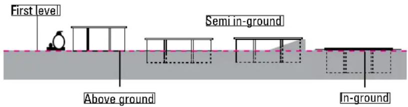
For on ground pools, we recommend protecting access to the pool by one standardized protection element.
For semi in-ground and fully in ground pools, the French law no. 2003-9 of 3rd January 2003. related to pool safety, as well as French decree no. 2003-1398 of 31st December 2003, related to pool safety, require protecting the pool by at least one element of standardized protection, like:
- Protection fence
- Pool alarm
- Pool cover
- Pool hut

INSTALLATION SUGGESTION
The land should be prepared as indicated in the «installation» chapter of this manual.
DO NOT SITUATE YOUR POOL
• Under overhead electricity cables
- Under branches of trees
- On non-stable land
A good location allows you to save time and avoid limitations. The pool should be in a sunny spot and easily reached.
The location of the pool should be free of tubes or electrical connections.
Take into account that the best is to assemble the pool on a sunny day and avoid high winds.
PACKAGING, CLASSIFICATION AND RECYCLING
- Some pool components are packed in plastic bags. To avoid all risk of asphyxia, never allow babies or children to play with these.
- Thanks for respecting the European Union Laws and collaborating in protecting the environment.
When you have installed your pool and all the components are assembled, we thank you for classifying and recycling all the packaging.
PROLOGUE
SAFETY INSTRUCTIONS
The filter kit (filter + pump) should be installed at least 3.5 metres from the pool to avoid the risk of electrocution.
There should be a special differential electricity protection device for pools with electric filter pumps, according to the regulation.
Never leave children without surveillance near the pool.
After each bath, remove the external stepladder to avoid accidental falling into the pool of children or of pets (Regulation EN-P90-317).
This pool is exclusively designed for family use. Walking on the edges or diving or jumping from them is strictly forbidden.
SAFETY ADVICES
Carefully read, understand, and follow all information in this user manual before installing and using the swimming pool.
These warnings, instructions, and safety guidelines address some common risks of water recreation, but they cannot cover all risks and dangers in all cases. Always use caution, common sense, and good judgment when enjoying any water activity. Retain this information for future use.
Non Swimmers safety
Continuous, active, and vigilant supervision of weak swimmers and non-swimmers by a competent adult is required at all times (remembering that children under five are at the highest risk of drowning).
- Designate a competent adult to supervise the pool each time it is being used.
- Weak swimmers or non-swimmers should wear personal protection equipment when using the pool. - When the pool is not in use, or unsupervised, remove all toys from the swimming pool and its surrounding
to avoid attracting children to the pool.
Safety devices
- It is recommended to install a barrier (and secure all doors and windows, where applicable) to prevent unauthorized access to the swimming pool.
- Barriers, pool covers, pool alarms, or similar safety devices are helpful aids, but they are not substitutes for continuous and competent adult supervision.
Safety equipment - It is recommended to keep rescue equipment (e.g. a ring buoy) by the pool.
- Keep a working phone and a list of emergency phone numbers near the pool.
Safe use of the pool - Encourage all users especially children to learn how to swim
- Learn Basic Life Support (Cardiopulmonary Resuscitation - CPR) and refresh this knowledge regularly.
This can make a life-saving difference in the event of an emergency. - Instruct all pool users, including children, what to do in case of an emergency
- Never dive into any shallow body of water. This can lead to serious injury or death.
- Do not use the swimming pool when using alcohol or medication that may impair your ability to safely use the pool.
- When pool covers are used, remove them completely from the water surface before entering the pool.
- Protect pool occupants from water related illnesses by keeping the pool water treated and practicing good hygiene. Consult the water treatment guidelines in the user's manual.
- Store chemicals (e.g. water treatment, cleaning or disinfection products) out of the reach of children.
- Signage is to be displayed in a prominent position within 2 m of the pool.
- Removable ladders shall be placed on a horizontal surface.

Loose parts available for 2 years counting from the product invoicing date.


WARNING:
Every electrical appliance fed in 220 V, has to be located at least at 3,50 m from the edge of the pool. The equipment should be connected to a voltage, with earth connection, protected by a residual current device (RCD) having a rated residual operating current not exceeding 30 mA.
Read the instructions carefully and keep for future reference.
IF YOU HAVE ANY PROBLEM, ..; CONTACT US!
www.gre.es

ATENCIÓN:

ATTENTION:

WICHTIGER HINWEIS

ATTENZIONE:
VOORSCHRIFTEN VOOR OPSLAG
VERPAKKING, AFVALSCHEIDING EN RECYCLING

BELANGRIJK:

ATENÇÃO:
Wood is a natural product, the fissures visible on the edges of the wood are completely normal and do not modify the resistance characteristics of the same.
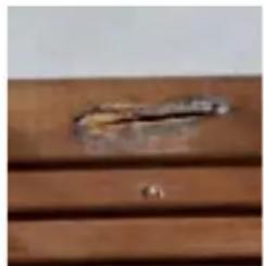
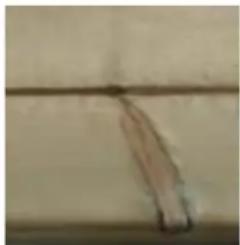
Wood is always a malleable material (from 3% to 4% of dimensional variations) with humidity and temperature oscillations. Therefore, small cracks can appear and in order to limit later deformations, the technical criteria have been respected regarding the design, the choice of sections, and of packaging and the fixing methods. Knots are natural elements of wood: their aspect and their size vary from one product to another. The secretion of resin is a natural phenomenon of resinous wood. Just as no tree is like another tree, the following photographed elements cannot be considered as defects:
ES LA MADERA: UN MATERIAL VIVO
natural_image
Close-up of a wooden plank with visible grain and a dark horizontal line (no text or symbols)Cracks/Grietas/Fente/Risse/Crepe/Barsten/Fendas
natural_image
Close-up of a wooden door handle with a small metallic clip and screw base (no text or symbols visible)Resin/Resina/Résine/Harz/Resina/Hars/Resinas
natural_image
Close-up of a thin, curved object against a plain background (no text or symbols visible)Nerves and long knots Nervios y nudos alargados Nervures et noeuds longs Geäder und lange knoten Nervature e nodi ingranditi Houtnerf en verlengde kwasten Nervuras e nós alongados
natural_image
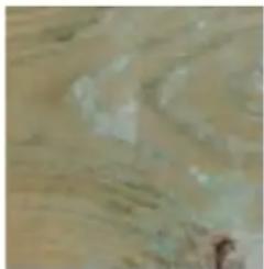
Close-up of a textured surface with indistinct light and dark patches (no visible text or symbols)Retention of sterilization products Retención de productos de esterilización Rétention de produits détuve Rückstände von Sterilisationsprodukten Ritenzione di prodotti per la sterilizzazione Vasthouden van impregnatiemiddelen Retenção de produtos de esterilização
natural_image
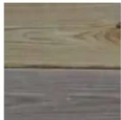
Close-up of a wooden surface with visible grain and texture (no text or symbols)Differences in shades of colour Diferencias de tonalidad Différences de teinte Unterschiede im Farbton Differenze di tonalità Kleurverschillen Diferenças de tonalidade
natural_image
Close-up of a textured brown surface with small white specks (no visible text or symbols)Surface mould/Moho superficial/Moisissures superficielles/Oberflächlicher moder/Muf fa superficialc/Oppervlakte-schimmel/Bolor superficial
natural_image
Two abstract, textured surfaces on a wooden surface (no text or symbols visible)Round knots/Nudos redondos/ Noeuds ronds/Runde knoten / Nodi rotondi/ Ronde kwasten/ Nós redondos
EN Mould can appear on the surface of wood, although not penetrating into it and not degrading it. After being treated with UV radiation, wood turns greyish with time without this affecting its durability. In addition to protection, varnish contributes to the beauty and long-life of wood.
SYLVESTER PINE TREATED IN AUTOCLAVE
The wood we use is select pine and dried to 2.5% before treatment in class IV autoclave. It has a 10-year guarantee against insect attack and against rot for the parts in the ground.
natural_image
Isometric illustration of a wooden cabin with slatted roof, ladder, and door (no text or symbols)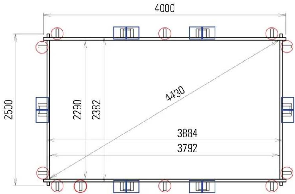
other
| Dimension | Value | | --------- | ----- | | Width | 4000 | | Height | 2500 | | Top Width | 2290 | | Bottom Width | 2382 | | Top Height | 4430 | | Bottom Height | 3884 | | Bottom Width | 3792 |

You should respect all these dimensions to perfectly adjust the liner and the edges.

The filter group and especially the electric pump should necessarily be located at a distance of at least 3.5 metres from the bowl (electricity regulation NFC-100).
WATER EVACUATION
2 Maintenance and wintering of the filter requires water evacuation. The evacuation should be foreseen when installing the filter group.
FILTER TUBE
3 In the case you want to bury the filter tubes, these should be protected against risk of deterioration, by protecting them with a cover before burying them.
POOL ORIENTATION
4 The pool should be positioned so the skimmer is facing the prevailing winds. The skimmer is a very important element in the filter system and is always installed facing the prevailing winds. The optimum filtering of the pool water depends on the suction capacity and position of the skimmer.

The filter group should be located below the level of the pool and ideally at floor level of the pool, otherwise there is a risk of the pump becoming deactivated. The filter pump should be protected from splashing of water, from floods, and from humidity, in a dry, well ventilated place. Otherwise,
the metallic pieces and the pump motor may become deteriorated.
GRUPO DE FILTRACIÓN
Advices to chose the best location for your pool:
- Select a place where you'll have to realize the least excavation to levelled the ground.
• Non easily inundated area in case of rain. - Where there is not any underground convection (water, gas, electricity...)
- Do not install it underneath electric line.
- Protected from wind and without any trees because the pollen and the leaves make the pool dirt.
- Sunny area, where the most sun is during the morning
- Close to a water and power supply and drainage system.
UNACCEPTABLE LOCATION: Sloping, uneven ground. Sandy, rocky or soggy ground.
There are two options to assemble this pool: A- Install the pool directly on the ground B- Prepare a concrete base of the dimensions indicated in the table. WE RECOMMEND OPTION B
Your pool can be installed in these three ways: Fig. 2
Whatever type of installation you choose, you should excavate and prepare the land for levelling.
Attention: in the case that the land is sloping, you need to excavate it for levelling. Do not add soil to level it.
In the case of assembling your pool above ground, you can use either a bed of sand or a concrete slab. If you choose the bed of sand, use fine and clean sand, otherwise you could stain the liner due to there being algae in the sand. In the case that the pool is semi-in-ground or completely in-ground, the installation should be using a concrete foundation slab. If a foundation concrete slab is used this should be at least 15 centimetres thick. The pool is assembled after the concrete foundation slab has completely dried (3 weeks).
The filter group should be located below the level of the pool and ideally at floor level of the pool.
A
PREPARING THE LAND
Levelling:
When levelling the ground, always remove material from the top of the slope rather than filling in the bottom: this will ensure greater ground stability and firmness. Always remove all grass, roots, stones, etc. Levelling is extremely important: devoting the necessary time and effort to ensuring that your pool sits properly on the ground will avoid problems later. How to level: thanks to a large mason rule (aluminium or wood) and a level, level out the ground forming rectangles (or squares), locating this rule in the selected and cleaned area. When all the areas are on level and when the excess of ground is removed, you may fill in the small areas which are left to level out (with clean ground or sand) but always compacting and levelling again afterwards. It is very important the installation area is well compressed and firm in order the ground do not subside when the pool will be full of water. Please ask a professional: builder, gardener.
natural_image
Black-and-white photo of a construction site with a large rectangular object and a tool, no visible text or symbols.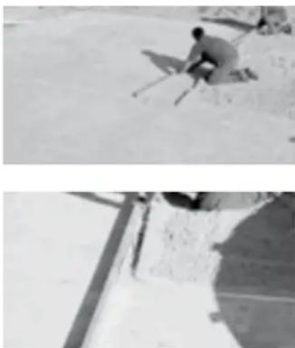
natural_image
Two black-and-white photos showing a person on a slope and another with a shadow on a wall (no text or symbols visible)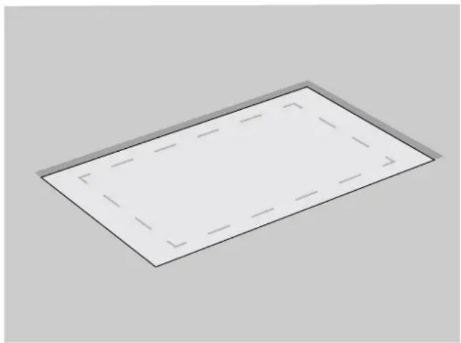
natural_image
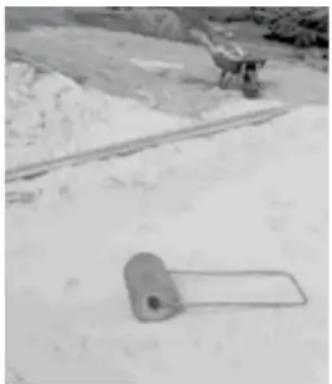
Simple 3D rectangular shape with dashed internal lines, no text or symbols presentFinishing:
On the cleaned and levelled ground, spred a light coat of sieved sand (max 1cm). Water and compact it (with a garden roller)
. Check that is well levelled. Do not use the sand to level the ground. The finishing has to be perfect. To install the pool properly, it has to be levelled. If it is not the case, the pressure differences on the contour might deform the stakes, or even make them split. Then, the water which would fall may damage the environment, or even cause accident.
Check again all the area level before beginning the following process: the assembling success depends on that phase.
A DIRECTLY ON THE GROUND
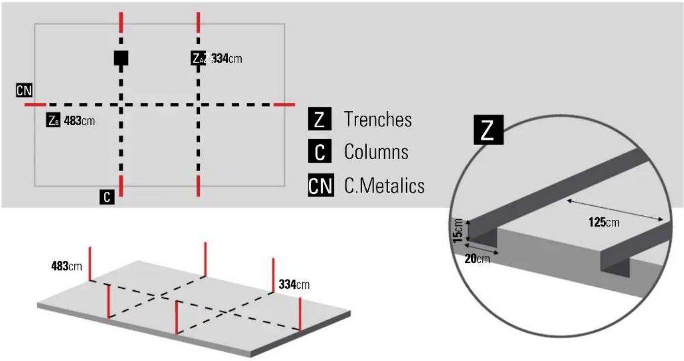
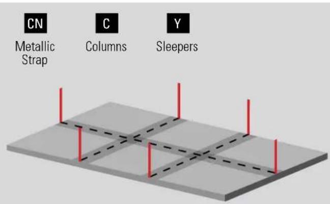
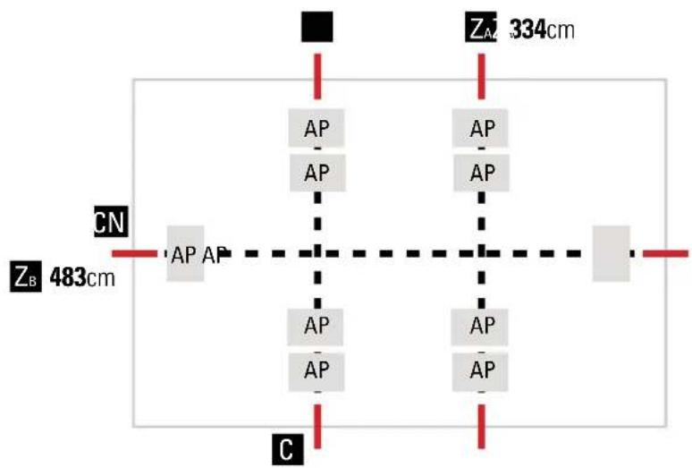
We recommend you assemble the pool between two or three persons and on a wind-free day. The use of gloves for the installation is recommended for safety. THE ENTIRE PROCESS SHOULD BE CARRIED OUT ON FIRM AND LEVEL GROUND, BEFORE EXCAVATING THE TRENCHES EXCAVATION OF THE TRENCHES (Z) FOR THE COLUMNS (C) AND METALLIC STRAPS (CN).
Dimension of the foundations: ZA = 334 cm ZB = 483 cm
The distance between them is 125 cm.
IMPORTANT: When excavating the foundations, the rectangular space reserved for situating the AP that should be buried 5 cm and transversally fixed with their respective PG should be excavated(*). All the structural system should be perfectly levelled (columns and internal structure, beams).
natural_image
Two outdoor construction site photos showing concrete foundation and soil dington with tools (no visible text or symbols)B CONCRETE BASE
B1 INSTALLATION OF POOL ON CONCRETE FLOOR
The floor should be perfectly horizontal and flat.
Lightly draw a rectangular surface according to the dimensions indicated in the table.
Before pouring the concrete, the structural system (columns and internal structure, beams) should be perfectly levelled), The distance between the centres of the columns is 1400 mm.
After building the structure, the framework can be placed over it.
Make sure that the structure is well fixed to avoid its movement when pouring the concrete. The base of the structure should be completely covered, with 2 cm of concrete over the PEAO base.
If you are going to use a concrete slab, the flanges should not be installed (AP).
Important:
In the case of being non-stable land, you should make a concrete slab instead of a bed of sand.
The bag should be perfectly flat and smooth, to avoid any imperfection.

We recommend to ask a professional to prepare the foundation slab.
1- Surrounding area
2- Concrete slab
The concrete slab is not included.
Dosing 350 kg/m ^3 (standardized type C125 430)
Ref. 790096
L: 5,20 x W: 3,70 x H: 0,15 m - 2,88 m3 concrete.
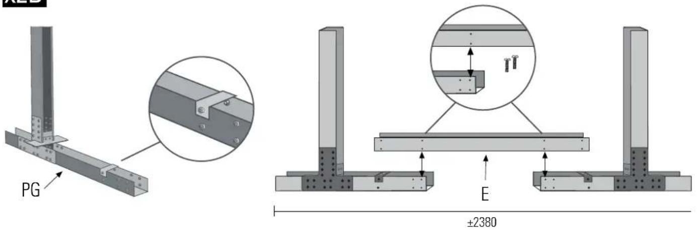
B2 INSTALLATION ON CONCRETE SLEEPERS
Always that the terrain is stable, the concrete slab can be replaced by concrete sleepers. This way, there is no need to build a complete concrete slab as indicated in point B1. You will need less time to build the sleepers and will save a considerable amount of concrete. If you are not sure about the stability of your terrain, we recommend that for safety reasons, you build a complete concrete slab.
Two sleepers at the centre of the pool at (90cm), and one perpendicular sleeper. The last sleeper is the longest because it is placed in longitudinal length of the pool.
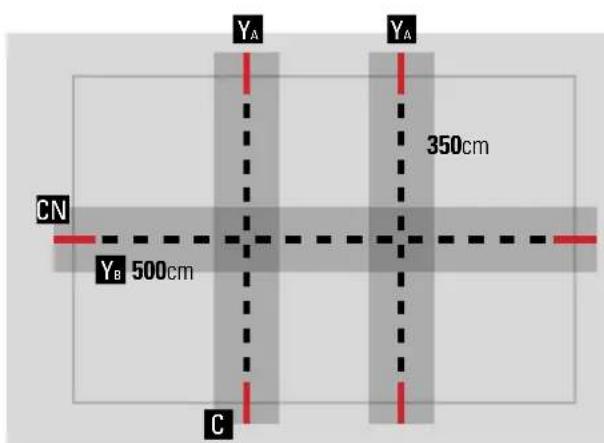
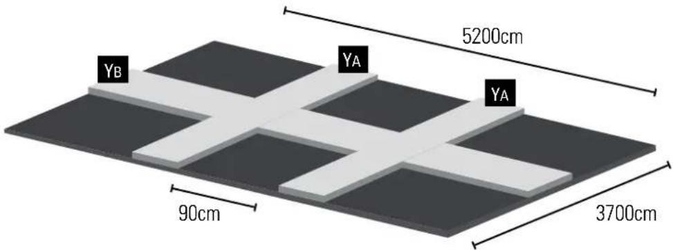
The (Y) concrete sleeper should have the following dimensions: Y_A=370×50×15cm Y_B=520×50×15cm .
All the sleepers must be levelled with each other for the pool to be perfectly level. The indicated dimensions and distances must be respected for correct assembly.
When the concrete is dry, the pool structure can be placed on top. The distance between the centres of the columns is 1400 mm. To do that, follow the next pages of this manual.
When the structures have been assembled on top of the concrete slabs, the entire structure must be fully covered with soil/sand. The terrain must be well-compacted for correct assembly of the pool. Pieces (AP) must be covered by at least 2cm of sand.
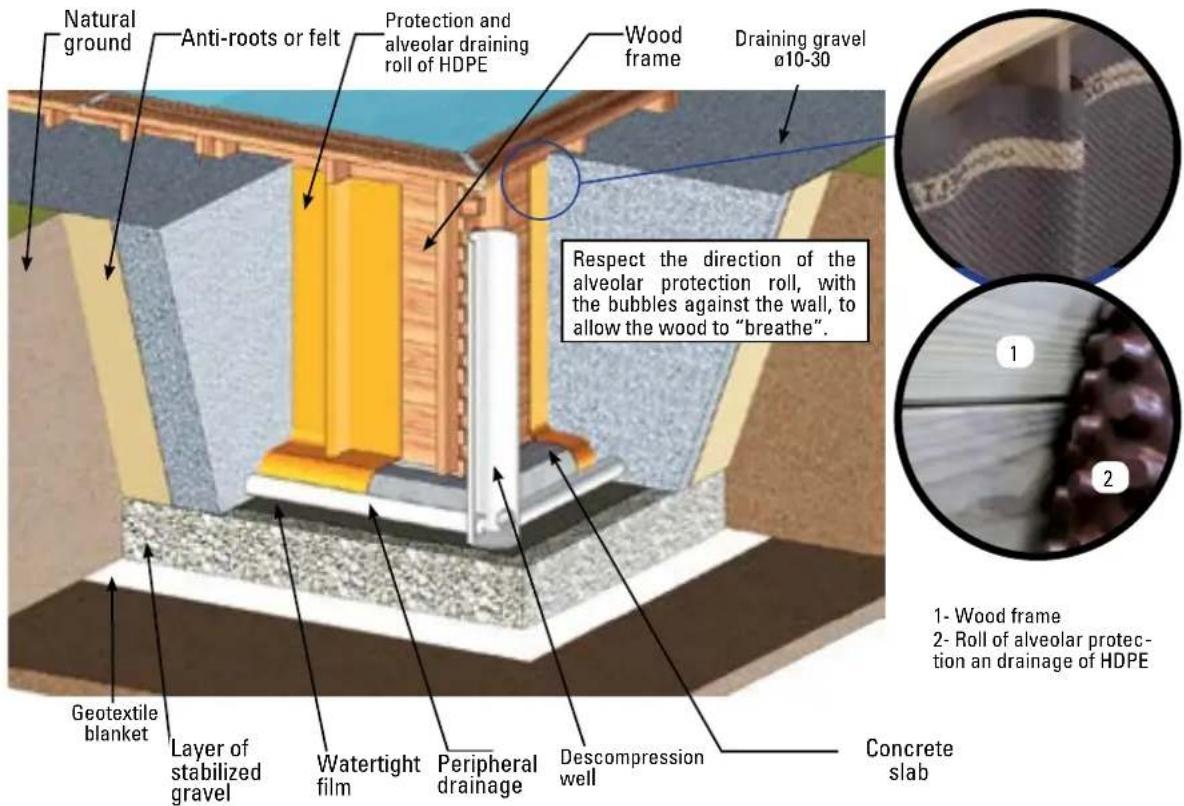
PARTIAL OR COMPLETELY IN-GROUND INSTALLATION
According to the nature of the land, you should install a peripheral drainage and connect it to a decompression well. The well will be excavated before the construction of the pool to avoid that the excavations fill with water during the works. It should be near the pool, a few centimetres lower than the deepest point of the same and reach up to the surface. The decompression well is located at the most humid point. It acts as an overflow in the case of water infiltrations or clay soil, starting from the fact that water rises quicker through a tube than through the soil.
ASSEMBLY OF THE COLUMNS
natural_image
Close-up of a metal L-shaped bracket with bolt holes, mounted on a concrete surface (no text or symbols visible)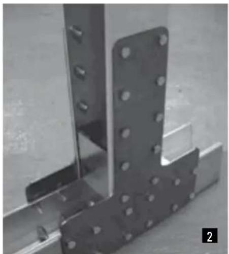
natural_image
Close-up of metal structural components with bolt holes and flange (no visible text or symbols)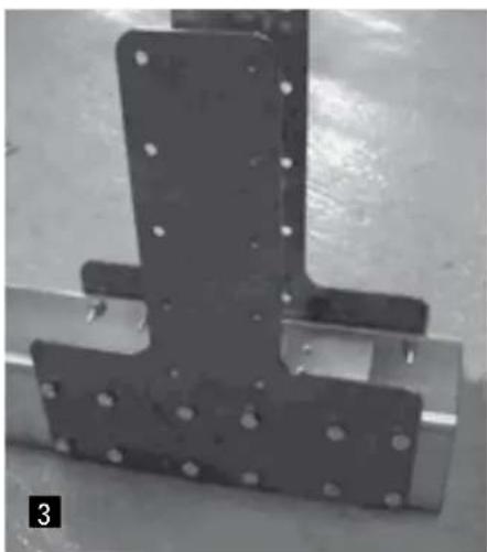
natural_image
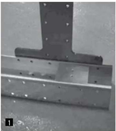
Close-up of a metal bracket with bolt holes and mounting holes (no text or symbols visible)- Assemble the six columns with parts 1PV1185 + 1 PG + 4 PEAO using the TV bolts.
NOTE: THE NUTS SHOULD ALWAYS BE LOCATED ON THE INSIDE. THE ENTIRE PROCESS SHOULD BE CARRIED OUT ON FIRM AND LEVEL GROUND, BEFORE EXCAVATING THE FOUNDATIONS. WE RECOMMEND ASSEMBLING THE PARTS IN A LARGE AND LEVEL SPACE, TO MAKE IT EASIER.
1
- Place the part PEU2 so that the four open holes on the sides with the second and third line of holes of the PG (see diagram 1b) and that the side where the holes are rests on the upper part. Bolt the TV bolts when the PEAO parts have been installed.
2
- Bolt the two PEA0 parts on each side of the PG crossbar, using the TV bolts and a spanner no. 13.
3
- Place the other PEU2 part on the lower part of the PV1185. Fix the column PV1185 to the PG beam bolt the TV bolts across the PEA0.
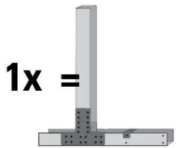
1 PV1185 + 1 PG + 4 PEA0 + 2 PEU2 + 1PEU
Z
Trenches
C
Columns
CN
C.Metalic
ASSEMBLY OF THE METALLIC STRIPS
x1A
IMPORTANT:
Install in the following order:
1- Metallic belt (x1A) lengthwise, so that the belt is supported on the bottom of trench.
2- Install the other 2 elements (x2B) as indicated by the drawing.
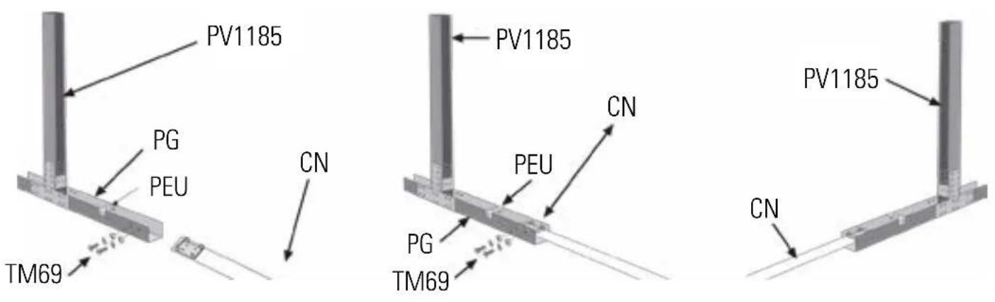
ASSEMBLY OF THE METALLIC STRAPS (CN) ON THE COLUMNS (C)
Bolt the part PEU with two upper holes in the centre of the PG part.
Bolt the end of each strap (CN) into the two upper holes of the end of the PG with the four TM& bolts and the two nuts TM69, very tight. Repeat this operation with all the straps (CN) according to the pool model.
Lastly, bolt the other ends corresponding to the PG of the column C (PV1185).
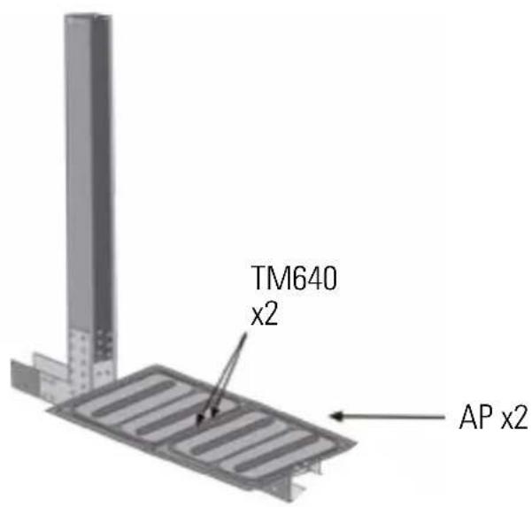
Place the flap AP so that it coincides with its two holes with those of the PEU part.
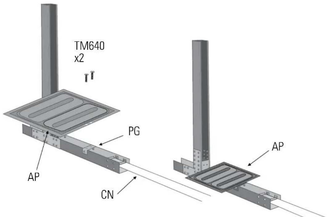
ASSEMBLY OF THE CROSSBASE AND THE COLUMNS
x2B

- Take the crossbar Part type E and fix the PG crossbar and the TV bolts. NOTE: there is only one crossbar between the PG crossbars (Part E).
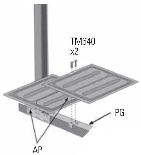
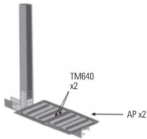
Place the flap AP so that it coincides with its two holes with those of the PEU part (the closest to the part PV1185). Then, place the other AP flap and fix them with two bolts TM640 (place the AP flaps after having introduced the support into the previously prepared ditch).
natural_image
Black-and-white photo of a construction site with a large tool and a rectangular component, no visible text or symbols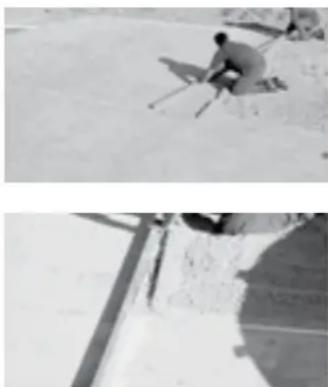
natural_image
Two black-and-white photos showing a person sitting on a seesaw and another with a shadow on a slope (no text or symbols visible)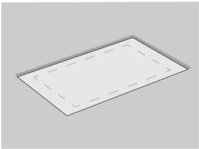
natural_image
Simple 3D rectangular plate with dashed inner lines, no text or symbols presentAcabado:
natural_image
Construction site with concrete foundation and metal framing, showing exposed soil and rebar grid (no text or symbols visible)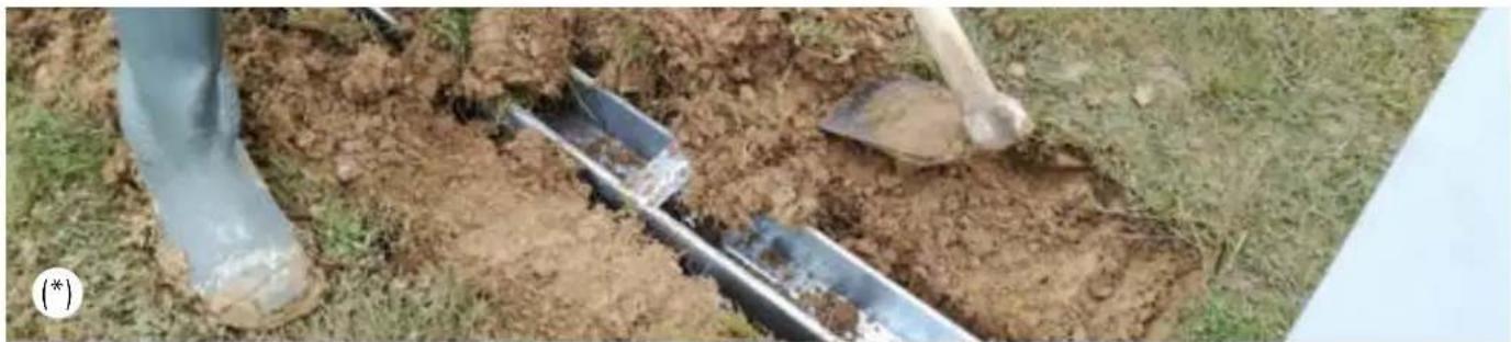
natural_image
Outdoor scene showing a person digging with shovels and a metal tool, surrounded by grass (no visible text or symbols)natural_image
Close-up of a metal L-shaped bracket with bolt holes, mounted on a concrete surface (no text or symbols visible)
natural_image
Close-up of metal structural components with bolt holes and flange (no visible text or symbols)
natural_image
Close-up of a metal bracket with bolt holes and mounting holes (no text or symbols visible)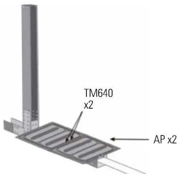
natural_image
Simple 3D diagram of a rectangular plate with dashed internal lines, no text or symbols present.
natural_image
Exterior view of a construction site with concrete foundations and a large tool (no signage or text visible)
natural_image
Two black-and-white photos showing a skier on a snowy slope and a close-up of the ground with a shadow (no text or symbols visible)Finition :
natural_image
Construction site with concrete foundation and metal framing, showing exposed soil and rebar grid (no text or symbols visible)
natural_image
Person digging with a metal tool in a muddy field, no visible text or symbolsB1 INSTALLATION DE LA PISCINE SUR UN SOL EN BÉTON
natural_image
Close-up of a metal L-shaped bracket with bolt holes, mounted on a concrete surface (no text or symbols visible)
natural_image
Close-up of metal structural components with bolt holes and flange (no visible text or symbols)
natural_image
Close-up of a metal bracket with bolt holes and mounting holes, no visible text or symbolsnatural_image
Simple 3D rectangular shape with dashed internal lines, no text or symbols present
natural_image
Exterior view of a construction site with excavator and concrete slab (no signage or text visible)
natural_image
Two black-and-white photos showing a person sitting on a seesaw and another with a long pole, both against a snowy landscape (no text or symbols visible)Finish:
natural_image
Construction site with concrete foundation and metal framing, showing exposed soil and rebar grid (no text or symbols visible)
natural_image
Person digging with shovels in a muddy field, no visible text or symbolsnatural_image
Close-up of a metal L-shaped bracket with bolt holes, mounted on a concrete surface (no text or symbols visible)
natural_image
Close-up of metal structural components with bolt holes and mounting brackets (no visible text or symbols)
natural_image
Close-up of a metal bracket with bolt holes and mounting holes, no visible text or symbolsnatural_image
Exterior view of a construction site with a concrete slab and a metal tool (no signage or text visible)
natural_image
Two black-and-white photos showing a person sitting on a slope and another with a shadow on a ground (no text or symbols visible)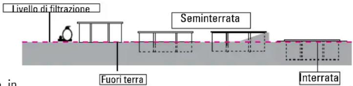
natural_image
Simple 3D diagram of a rectangular plate with dashed lines indicating hidden edges (no text or symbols)Finitura:
natural_image
Two outdoor construction site photos showing concrete foundation and soil dington with tools (no visible text or symbols)B1 MONTAGGIO DELLA PISCINA SU UNA SOLETTA IN CEMENTO ARMATO
natural_image
Close-up of a metal L-shaped bracket with bolt holes, mounted on a concrete surface (no text or symbols visible)
natural_image
Close-up of metal structural components with bolt holes and mounting brackets (no visible text or symbols)
natural_image
Close-up of a metal bracket with bolt holes and mounting holes (no text or symbols visible)
natural_image
Simple 3D rectangular shape with dashed internal lines, no text or symbols present
natural_image
Aerial view of a mining site with a large tool and a rectangular equipment component (no visible text or symbols)
natural_image
Person skiing on a snowy slope with another person visible in the background (no text or symbols)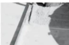
natural_image
Close-up of a textured surface with diagonal lines and a small dark object (no visible text or symbols)Afwerking:
natural_image
Two outdoor construction site photos showing concrete foundation and soil dington with metal framing (no visible text or symbols)B1 HET ZWEMBAD OP EEN BETONNEN ONDERGROND PLAATSEN
natural_image
Close-up of a metal L-shaped bracket with bolt holes, mounted on a concrete surface (no text or symbols visible)
natural_image
Close-up of metal structural components with bolt holes and mounting brackets (no text or symbols visible)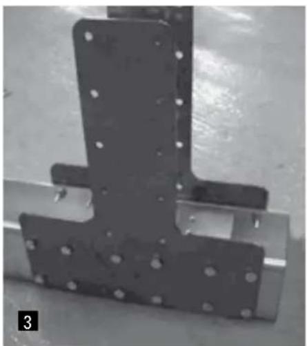
natural_image
Close-up of a black metal bracket with bolt holes, mounted on a metal frame (no visible text or symbols)- Monteer de zes staande balken aan de onderdelen 1 PV1185 + 1 PG + 4 PEAO met behulp van de bouten TV. LET OP: DE MOEREN MOETEN ZICH ALTIJD AAN DE BINNENZIJDE BEVINDEN. DIT HELE PROCES MOET WORDEN UITGEVOERD OP EEN STEVIGE EN GEËFFENDE ONDERGROND VOORDAT DE GEULEN WORDEN GEGRAVEN. OM DIT PROCES TE VERGEMAKKELIJKEN, IS HET BELANGRIJK OM DE ONDERDELEN TE MONTEREN OP EEN PLEK DIE GOED GEËFFEND IS EN RUIMTE BIEDT.
1

natural_image
Simple 3D rectangular panel with dashed internal lines, no text or symbols present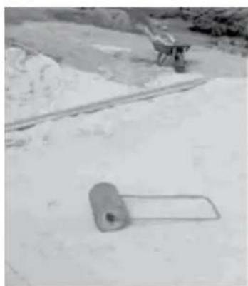
natural_image
Exterior view of a construction site with a concrete structure and a tool (no signage or text visible)
natural_image
Person skiing on a snowy slope with another person visible in the background (no text or symbols)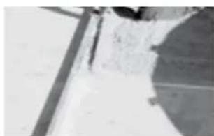
natural_image
Close-up of a metallic surface with visible cracks and texture (no text or symbols)Acabamento:
natural_image
Two outdoor construction site photos showing concrete foundation and soil dington with tools (no visible text or symbols)MONTAGEM DAS COLUNAS

natural_image
Close-up of a metal L-shaped bracket with bolt holes, mounted on a concrete surface (no text or symbols visible)
natural_image
Close-up of metal structural components with bolt holes and mounting brackets (no visible text or symbols)
natural_image
Close-up of a metal bracket with bolt holes and mounting holes (no text or symbols visible)MONTAGEM DAS CORREIAS METÁLICAS (CN) NAS COLUNAS (C)
MONTAGEM DAS TRAVESSAS E DAS COLUNAS
x2B
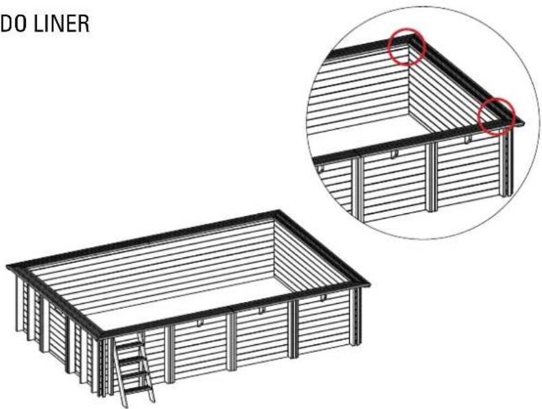
EN • Unroll the blanket and cut each piece. (It is better to use scissors instead of a cutter)
- Cut 3 pieces of 630~cm from the roll, of 1,30m width.
Dimensions of the final blanket: 630x390 cm. Unroll the blanket taking into account how the pool is oriented. The pool will be situated over the blanket as shown in Fig. 12.
natural_image
Simple illustration of a white sheet with orange stripes and a small orange ring on top (no text or symbols)EN After having done the installation and preparation of the ground you can start with assembling the pool. Start by laying the protective blanket, which should be cut from the roll included, on the floor.
Scrupulously respect the indicated measures to cut the roll.
• Join the pieces without them overlaying. • Do not have any folds.
- Join the pieces by the edges using single-face adhesive tape.
natural_image
Close-up of two wooden blocks arranged in an L-shape on a plain background (no text or symbols visible)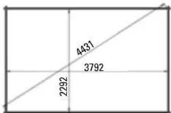
geo
| Dimension | Value | |---|---| | Top Right | 4431 | | Bottom Left | 2292 | | Bottom Right | 3792 | The chart displays a single rectangular area with three equal side lengths (3792 and 2292) and a diagonal line extending from the bottom-left to the top-right corner. There is no explicit numerical labels or axes provided in the image.Prepare the boards «as trial» • Coloque las tablas «de prueba» • Disposez les madriers «à blanc» • Platzieren Sie die „Test“-Bretter • Posizionare le tavole «di prova» • Plaats de planken in «proefopstelling» • Coloque as tábuas «de prova»

LAYOUT OF THE BOARDS: Prepare the boards «as trial», forming the silhouette of the pool.
INSTALLATION OF THE FIRST LAYER OF BOARDS: • Build the first layer placing borads (A38) and (B15) as shown by figure 2. • Adjust the shape of the pool using the inside dimensions indicated in the installation diagram (see page 42-43). • The drawing shows the inside dimensions of the pool for the different opposing diagonals. After having installed de first layer, you should check the inside dimensions of the pool.

EN After having installed the first layer, you should check the inside dimensions of the pool. For a perfect assembly, the diagonals should be equal, and in conformity with the assembly drawing at the end of this manual. Take special care when installing this first layer of boards. The precision of this assembly decides the final quality of your pool.
natural_image
Person using a tool to block wood on a wooden beam (no text or symbols visible)Using a mallet, hit the wooden wedge so it fits deeply into the boards•Con ayuda de un mazo, golpee la cuña de madera para encajar en profundidad las tablas•A l'aide d'un maillet, frappez sur le cale en bois pour emboîter à fond les madriers•Schlagen Sie mit Hilfe eines Holzhammers auf den Holzkeil, um die Bretter voll und ganz einzupassen•Con l'aiuto di una mazza, colpire il cuneo di legno per incastrare le tavole in profondità•Sla de houten wig met behulp van een rubberhamer op zijn plek om de planken zo stevig mogelijk in elkaar te laten passen•Com a ajuda de um maço, bata no calço de madeira para encaixar as tábuas em profundidade
Layout of the boards • Disposición de las tablas • Positionnement des madriers • Anordnung der Holzbretter • Disposizione delle tavole • Plaatsing van de planken • Disposição das tábuas
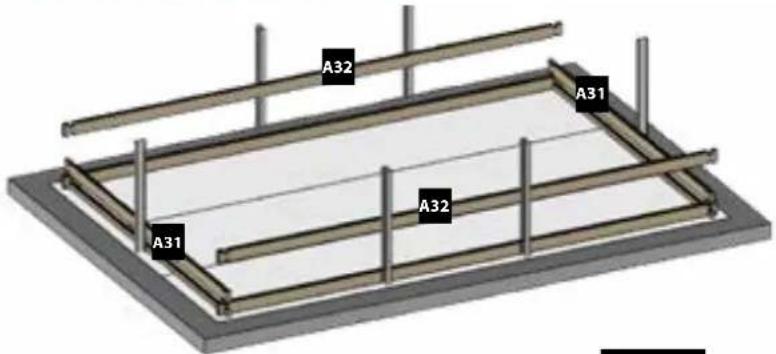
Fig. 3
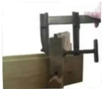
EN 2nd LAYER OF BOARDS: • Install the second layer of boards as shown in figure 3. • There is a wooden wedge in the structure packet to correctly assemble the boards. • Never directly hit against the boards. You would damage the pegs and would weaken the structure. Do not hit them with anything metallic. This would inevitably damage the wood. • Try to correctly assemble the boards right from the start. There should not be any space between each layer of boards to avoid maladjustment of the higher boards.
natural_image
Close-up of a hand operating a wooden clamping device (no text or symbols visible)Loose board • Tabla suelta • Madrier voilé • Loses Brett • Tavola libera • Losse plank • Tábua solta
natural_image
Close-up of a mechanical clamping device with no visible text or symbolsRedirected board • Tabla redirigida • Madrier redressé • neu ausgerichtetes Brett • Tavola riposizionata • Rechtgebogen plank • Tábua redirigida
EN 3rd LAYER OF BOARDS: Install the third layer of boards as shown in figure 4. The position of the refilling fitting with the key and the skimmer should be defined at the start of the assembly (read the specific paragraphs).
4th AND FOLLOWING LAYERS OF BOARDS: Place the boards and the following layers repeating the alternations of the second and of the third layer.
SPECIFIC BOARDS: Refilling fitting with key: place the specific board for the refilling with key (E15) situating the larger diameter on the external side of the pool.
natural_image
Simple circular diagram with a central cylindrical object and a horizontal line, no text or symbols present.larger diameter on exterior
refrentado lado exterior
WOODEN BLOCKS, REINFORCEMENTS AND TRIMMINGS
TACOS, REFUERZOS Y EMBELLECEDORES
CONSOLES, RENFORTS ET CACHES
Assemble the wooden stepladder and use it as a template to define the separation of the wooden blocks that support it.
ES LEA DETENIDAMENTE EL APARTADO COMPLETO ANTES DE ATORNILLAR NINGUNA PIEZA A SU PISCINA
EN The position of the wooden blocks and of the reinforcements is indicated in the drawing (See page 42-43). The wooden stepladder can also be used for positioning the wooden blocks, see stepladder chapter.
WOODEN BLOCKS
A • Align the upper part of the wooden blocks with the level of the last board. Maintain the wooden blocks in their place.
B- Drill the boards with a ∅ 6 mm bit for wood. Tighten the screws in 2 times, from inside the pool.
- First tighten the upper screws into the wooden blocks and the lower ones (in the 1st and 2nd boards). Systematically check that the upper part of the wooden block.
- Make sure that the head of the screw is level with the surface of the wood. The wooden blocks are designed to support the edges.
natural_image
Close-up of a green wooden block joint with visible mortar and rebar (no text or symbols)Align the wooden block with the upper part of the board
natural_image
Close-up of a blue electric drill bit on wooden surface, no visible text or symbolsFix the wooden blocks with the 6 x 90 screws (1 screw per board)
- Align the upper part of the reinforcements with the level of the last board. Maintain the reinforcements in their place. - Drill the boards with a 0.6mm bit for wood. Tighten the screws in 2 times, from inside the pool. - First tighten the upper screws into the reinforcements and then the lower ones (in the 1st and last boards). - Check the verticality of the reinforcements. - Finish assembling the reinforcements using 1 screw per board and correct possible deformations of the wood (boards). Systematically check that the upper part of the reinforcement is well aligned with that of the board and that the head of the screw is level with the surface of the wood.
ES REFUERZOS
natural_image
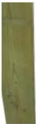
Close-up of a wooden door and textured floor surface (no visible text or symbols)The reinforcement need not necessarily touch the ground El refuerzo no toca obligatoriamente el suelo Le renfort ne touche pas obligatoirement le sol Die Verstärkung berührt nicht zwangsweise den Boden Il rinforzo non deve toccare obbligatoriamente il suelo De versteviging hoeven niet persé de grond te raken O reforço não toca obligatoriamente no solo
natural_image
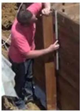
Person in red shirt installing or adjusting a wooden door panel outdoors (no visible text or symbols)Check the verticality of the reinforcements Compruebe la verticalidad de los refuerzos Contrôlez l'aplomb des renforts PrüfenSiedievertikaleAusrichtungderVerstärkungen Accertarsi della verticalità dei rinforzi Controleer of de verstevigingen lodrecht zijn Verifique a verticalidade dos reforços
natural_image
Close-up of a wooden plank with visible grain and knots (no text or symbols)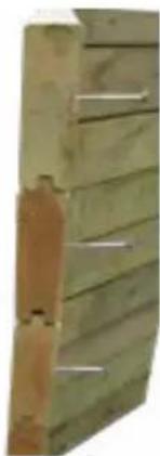
natural_image
Close-up of a wooden fence with metal bars, no visible text or symbols
TRIMMINGS L
- Position the L trimming on the ends of the boards. - Cut off the excess part of the trimming according to the height of the pool if necessary (figure 6). - Fix trimming L using 3 screws 4 × 60 uniformly distributed over the height of the piece (figure 7).
This finishes the assembly of the structure. Now all that needs doing is to position the edges (see the edges chapter).
At this time of the assembly:
- The skimmer is positioned facing the prevailing winds. - The panel of the structure on which the removable stepladder will be located has been decided.

EMBELLECEDORES L
The trims are complementary reinforcements that allow you to hide the visible sections of the metal parts. They are attached to the pool like the rest of the reinforcements and have a cross member (figure 8) that hides the outside face of the frame.
EMBELLECEDORES DEL BASTIDOR METÁLICO
The wooden stepladder is included for access to the pool. Do not use for anything else.
Assemble the wooden stepladder and use it as a template to define the separation of the wooden blocks that support it. In the case that the pool ahs an elongated shape, the stepladder will be positioned on a small side.
Centre the external stepladder in relation to the side.
Drill with a ∅ 10 mm bit for wood the 2 support and the 2 wooden blocks.
Do not use the stepladder for other needs different to those indicated in this manual.
Admitted maximum weight = 150 kgs.
Its is COMPULSORY to remove the stepladder after using the pool.
According to the height of the pool, the stepladder may need adjusting.
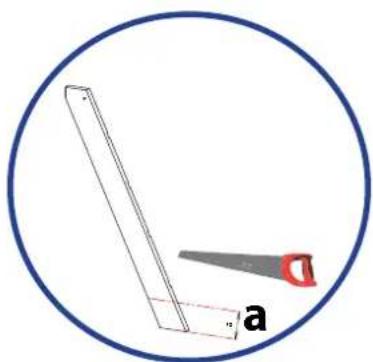
- Cut the supports of the ladder checking the dimensions as shown in (figure 9) at the bottom part of the stepladder support and saw off the part you do not need.
- Assemble the stepladder and position it as shown in figure 10.

natural_image
Architectural detail showing wooden beams and structural components (no text or symbols)Fig. 9/ Abb. 9 / Afb. 9
natural_image
Simple line drawing of a saw and a rectangular object inside a circle (no text or symbols)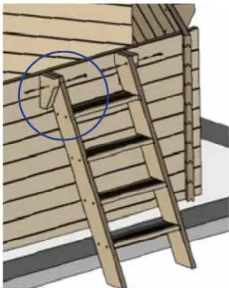
natural_image
Architectural detail showing wooden ladder and ladder assembly (no text or symbols)Fig. 10/ Abb. 10 / Afb. 10

EN In the case that the pool is partially in-ground the stepladder should be cut to adapt it to the pool. For safety reasons, if the space between the floor and the first step is between 80 and 230mm (dimension A) close this space using the step of the ladder you have removed so that dimension B is less than 89mm . To do that, follow these steps:
1- Reduce the length of the step by 12 mm.
2- If dimension A is less than 140 mm, reduce the width of the step so that when the step is installed the space below its is completely closed.
3- Assemble the modified step in the stepladder as shown in the upper diagram, trying to pre-cut the stepladder support.
natural_image
Silhouette of a person holding a tool near a wall, labeled 'Fig. 11' (no other text or symbols)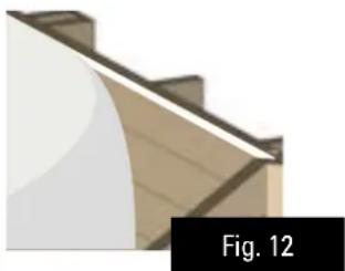
natural_image
Close-up of a wooden roof corner with visible grain and construction details (no text or symbols)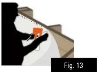
natural_image
Silhouette of a person holding an orange object, with no visible text or symbols
There are two possibilities to install the wall protecting blanket
TWO FACED ADHESIVE TAPE (NOT INCLUDED)
- Stick the two-faced adhesive tape panel by panel, aligning it with the upper part of the top boards (figure 11). If the wood is slightly humid and dusty, it can be smoothened using sandpaper to facilitate adherence.
- Check that the walls and floor are clean.. Remove screws, bark, shavings, sawdust...
- Unroll the blanket aligning it to the upper edge of the top boards (figure 12).
- Cut of the excess blanket and eliminate any folds.
STAPLER (NOT INCLUDED)
- Staple the end of the blanket starting from a corner.
- Unroll the blanket aligning it to the upper edge of the top boards.
Use one staple every 20 cm. (figure 13)
- Cut of the excess blanket and eliminate any folds.

ADHESIVO DE DOBLE CARA (NO INCLUIDO)
natural_image
Technical line drawing of a mechanical component with two views (top and side), no visible text or symbolsFixing of the skimmer joint
The skimmer is the water suction point from the pool to the filter. Its position facing the prevailing
winds allows recovery of all the possible residues floating on the surface of the water (dust, leaves...)
INSTALLATION
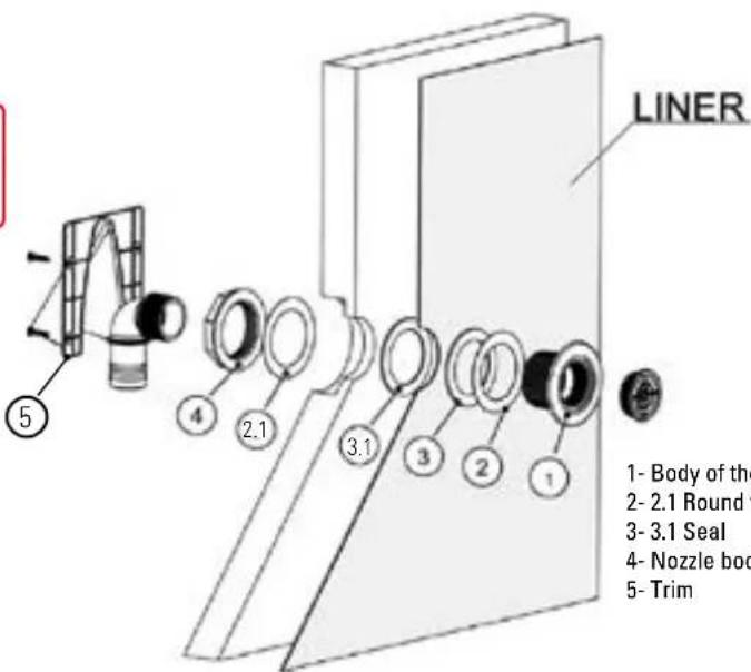
- Fix the first watertight seal (flat joint) to the body of the skimmer using the 4 round-head screws, respecting the illustrated position.
ES
EN The refilling fitting with key is for introducing water into the pool. It goes through the wall through the hole made in the pre-cut board. INSTALLATION
- Locate the position of the hole for the nozzle.
- Male a cross-shaped cut in the blanket from inside the pool.
- Cut the blanket with a cutter.. The cut will be larger than the hole (hole radius + 2 cm).
- Cut the blanket with a cutter.. The cut will be larger than the hole (hole radius + 2 cm). The automatic cleaner connection of the skimmer is only used for pool maintenance.
natural_image
Technical line drawing of a mechanical bracket or housing component (no text or symbols)EN -Only if the pieces are included in the pool
ES - Unicamente si las piezas están incluidas en su piscina
FR - Seulement si les pièces sont incluses dans le bassin
DE - Nur wenn das Schwimmbad die Teile dabei hat
IT - Solamente se i pezzi sono inclusi nella sua piscina
NL - Alleen als de stukken zijn inbegrepen bij het zwembad
PT - Somente se as peças estiverem incluídas na sua piscina
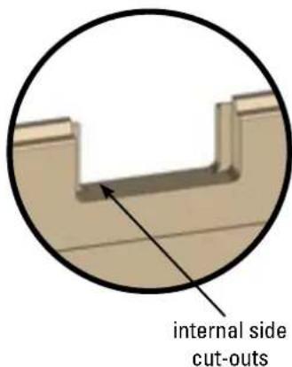
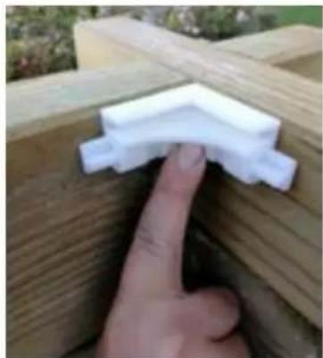
EN·Locate some white parts in the bag. Present the piece in the joint of two boards as shown in the photograph and in the following photo.
ES Localice unas piezas blancas en la bolsa. Presente la pieza en la unión de dos maderas como se muestra en la foto y el el siguiente dibujo.
- Utilisez les pièces blanches du sachet. Présentez la pièce dans l'union des deux bois comme cela est indiqué sur la photo et sur le dessin suivant.
DE. Suchen Sie in der Packung nach mehreren weißen Teilen. Halten Sie ein Teil entsprechend dem Foto und der nachfolgenden Zeichnung an die Stoßstelle zweier Holzteile.
IT. Individuare i pezzi bianchi nel sacchetto. Posizionare il pezzo nella giuntura di due parti in legno come mostrato nell'immagine e nel disegno riportato a continuazione.
NL Haal de witte stukken uit de zak. Plaats het stuk op de verbinding van de twee houten balken zoals u op de volgende foto's en afbeelding kunt zie.
- Localize as peças brancas na saqueta. Coloque a peça na união das madeiras, tal como se observa na fotografia e no seguinte desenho.
EN - Screw in the piece using two screws 4x40 mm.
ES · Atornille la pieza utilizando dos tornillos 4x40 mm.
FR - Vissez la pièce avec deux vis 4x40 mm.
DE - Schrauben Sie das Teil mit zwei Schrauben 4x40 mm fest.
IT · Avvitare il pezzo con due viti 4x40 mm.
NL · Schroef het stuk vast en gebruik daar twee schroeven voor van 4x40 mm.
PT · Aparafuse a peça com dois parafusos 4x40 mm.
natural_image
Close-up of a hand touching a white PVC component on a wooden deck (no text or symbols visible)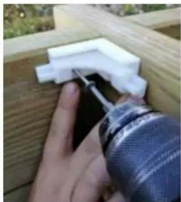
natural_image
Close-up of a hand using a tool to apply plastic components on a wooden deck (no text or symbols visible)natural_image
Close-up of a wooden deck with a white plastic clip attached, next to a brick wall and concrete structure (no text or symbols visible)EN. The piece should be fixed at both ends.
ES · La pieza debe quedar fijada por ambos extremos
FR · La pièce doit être correctement fixée par les deux extrémités.
DE · Das Teil muss später von beiden Seiten fixiert sein.
IT - Il pezzo deve essere fissato ad entrambe le estremità
NL · Het stuk moet aan beide uiteinden worden vastgezet
PT · A peça deve ficar corretamente fixada em ambos os extremos
natural_image
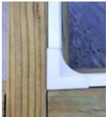
Close-up of wooden panel corner with vertical bracing and a curved wall detail (no text or symbols visible)Note: these parts are for aesthetics. Probably not all the corners are perfectly fixed. It will depend on the temperature of the liner and your ability for its installation. If the liner is not perfectly distributed around the pool, not all the corners will be fixed. In that case, there is not any problem, you must not worry, because it is only an aesthetic part.
natural_image
3D rendering of a saw cutting through a metal frame structure (no text or symbols visible)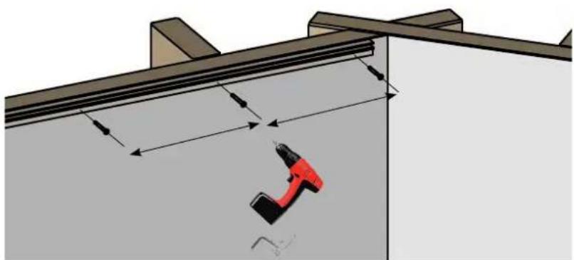
natural_image
Diagram of a mechanical assembly with a red tool inserted into a wall, showing dimension arrows (no text or symbols)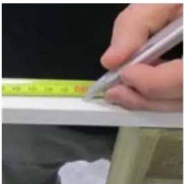
natural_image
Close-up of a hand using a pen to mark a white object on a surface, with a yellow ruler partially visible (no text or symbols)Take the measurement
natural_image
Close-up of a hand holding a tool, no visible text or symbolsand cut the liner profile • y corte el perfil del liner • et découpe de la baguette de liner • und schneiden Sie das Profil des Liners ab • e tagliare il profilo del liner • en zaag het klemprofiel van de liner op maat • e corte o perfil do liner
natural_image
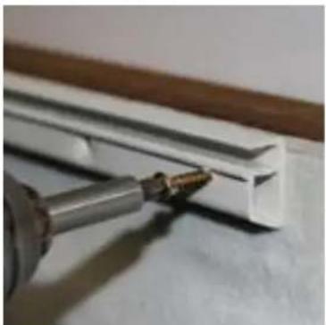
Close-up of a metallic tool interacting with a white plastic bracket (no visible text or symbols)natural_image
Exterior view of a white wall corner with a vertical seam, no visible text or symbolsInstallation of the profiles in the same panel • Colocación de los listones en un mismo panel • Positionnement des baguettes sur un même pan • Positionierung der Leisten an demselben Paneel • Posizionamento dei profili su uno stesso pannello • Plaatsing van de Klemprofielen in een enkel paneel • Colocação dos perfis num mesmo painel
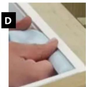
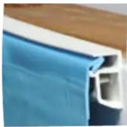
EN The liner should be introduced as shown in the following image.
natural_image
Close-up of a hand inserting a white plastic component into a wooden drawer (no text or symbols visible)EN PREVIOUS CHECK BEFORE INSTALLING THE LINER
- Clean the inside structure of the pool (grains of sand, screws...) use a vacuum cleaner if necessary.
- Check that the skimmer seal is in its place.
- Position the trap door inside the skimmer.
- Check that there are no screw heads protruding above the surface of the wood.
ES
EN The liner should have been at least 24 hours at a room temperature of at least 20 °C before being installed. The dimension of the liner are a few centimetres shorter than the inside dimensions of the pool, so the liner is tensely installed. The liner should be installed at an external temperature of at least 15 °C. We extremely recommend putting the liner in the sun a few hours before assembly, so it is flexible and easy to install. The sticker with the serial number of the liner should be kept for future reference. This number will be required for any eventual reclamation against the guarantee.
INSTALLATION
To do this, you should take off your shoes to not damage the liner.
A Enter the pool, without wearing shoes.
B Place the liner in the centre of the pool (figure 14) and unfold it starting from there (figure 15) Uniformly distribute the space between the dimensions of the liner and those the structure all round.
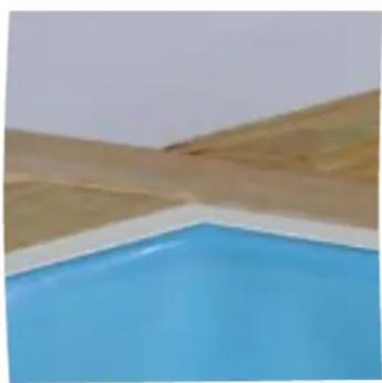
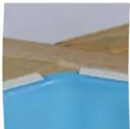
C Correctly align the lower angles of the liner (angles of the floor closures) with the corners of the pool (figure 16).
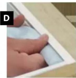
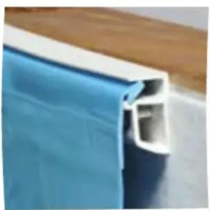
D Insert the hooking profile of the liner into the profile (figure 17).
The liner should have been at least 24 hours at a room temperature of at least 20^ C before being installed. The liner should be installed at an external temperature of at least 15^ C.
natural_image
Person in a blue shirt standing inside a light blue rectangular container, with wooden crates and red equipment in the background (no visible text or symbols)Fig. 16
natural_image
Close-up of a hand holding a white cylindrical object inside a wooden frame (no visible text or symbols)Fig. 17

natural_image
Person in blue jacket standing inside a large blue container at a construction or excavation site (no visible text or symbols)Fig. 16 / Abb. 16 / Afb. 16
natural_image
Close-up of a hand holding a white cylindrical object inside a wooden box (no visible text or symbols)Abb. 17 / Afb. 17

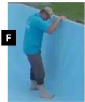
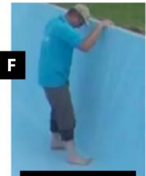
E To move the already installed liner, slide it along the profile. If this is difficult the liner can be removed by lifting it not to damage it. Make sure that the liner is well positioned both on the floor as on the walls, uniformly adjust the tension of the same (with your foot, push the liner by its angles towards the corners of the walls) (figure 18).
F Fit the pool with about two centimetres of water (figure 19). To facilitate installing the liner, this water should be very cold.
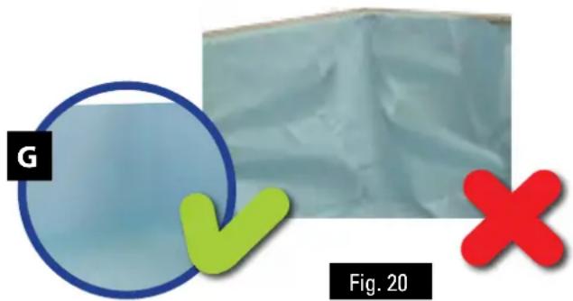
G Flattern the bottom of the liner to avoid folds starting from the centre towards the edges. Continue filling the pool. If there are still folds, correct the tension of the liner at the walls by sliding it along the hooking profile. (Oblique folds in the wall indicate incorrect positioning) (figure 20).
The angles of the liner should necessarily correspond to the corners of the pool structure.
Once the liner is installed, continue filling the pool up to 10 cm below the refilling fitting with key.
Some weeks after filling the pool, the liner will show a different colour between the submerged part and that in the air. This decolouration is normal and does not risk the sturdiness and/or characteristics of the liner. To avoid that a dark mark appears due to atmospheric contamination between the submerged part and the part of the liner in the air, (called water line), we recommend regularly cleaning the liner in this area with a specific cleaner.

natural_image
Person in blue shirt and gray pants walking on a large white tarp outdoors (no visible text or symbols)Fig. 18 Fi
natural_image
Person in blue shirt and gray pants climbing a blue wall (no visible text or symbols)The Ground Truth image displays a single, solid horizontal line. According to Rule 2 (UNDERSCORE & LINE RULES), this is a stylistic or background line, not a placeholder underscore. Therefore, the OCR result must ignore it. The provided OCR content is "____", which consists of four underscores. This is an incorrect interpretation of the line as a placeholder, violating the rule that stylistic lines must be ignored. The OCR has hallucinated underscores where none should exist based on the GT's visual context. Hence, the OCR result is inconsistent with the Ground Truth.
natural_image
Close-up of a blue and white plastic panel with a hollow cutout, placed on a wooden surface (no text or symbols visible)This transversal view shows the liner placed in the angle. Esta vista transversal muestra el liner colocado en el ángulo. Cette vue en coupe mantre le liner en place dans la cornière
natural_image
Exterior view of a modern office building (no signage)Tense the liner well at the corners Tense bien el liner en las esquinas Tendez bien le liner dans les angles

natural_image
Person in a light blue shirt and brown pants walking on a large white tarp outdoors (no visible text or symbols)Fig. 18 / Abb. 18 / Afb. 18
natural_image
Person in blue shirt and gray pants climbing a blue wall (no visible text or symbols)Abb. 19 / Afb. 19
natural_image
Close-up of a blue plastic panel with white cutouts, no visible text or symbolsDiese Querschnittansicht zeigt den im Anschlusswinkel positionierten Liner
Questa vista trasversale mostra il liner posizionato nell'angolo
Deze zijaanblik toont de in een hoek geplaatste liner
Esta vista transversal mostra o liner colocado no ângulo

natural_image
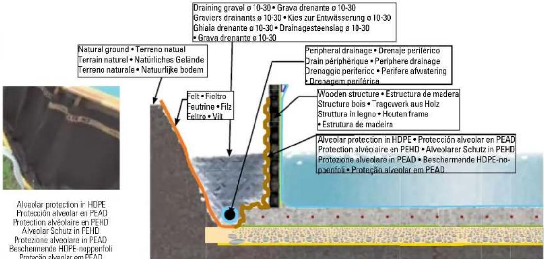
Exterior view of a modern office building (no signage)EN In fully or partially in-ground pools, a gravel landfill is necessary to favour perfect draining. The landfill of a pool can seem a mere formality, because a first sight there are no special technical difficulties. Nevertheless, it is a more delicate operation than what it seems, for which certain precautions are necessary. An incorrect landfill can give way to later deterioration of the pool and its surroundings. It is necessary to consider the type of material being used and to perform all the necessary verifications. Before performing the landfill, you should:
- Check that all the hydraulic and electrical equipment is well connected. - Check the water tightness of the connections of the channelling, especially regarding those sealed parts. - Protect, if applicable, the peripheral
draining tube covering it with geotextile. It is important to fill the pool in parallel to the landfill in order to balance the pressures and that way avoid deformations of the structure during the operation. We recommend following the landfill technique by thirds (1/3 of water and 1/3 of landfill). During the landfill, we recommend processing by successive layers around the entire perimeter of the pool to not run the risk of damaging the structure. • Position the alveolar HDPE protection (not included) around the pool.. The alveolar protection, should, likewise continue over the slab and all round the outside of the same. • To avoid draining obstruction, you should place felt on the natural soil (not included) to retain the soil. • Install the peripheral draining over the protection and connect it to the decompression well (if applicable). Otherwise, leave the draining extended over the land. • Now, make the landfill against the walls with compacted gravel (10/30 calibre) that will facilitate drainage. This landfill should be done at the same time that you fill the pool. Land-filling with vegetable soil is prohibited.

INFORMATION: The drainage allows the continuous evacuation of water, at the foot of the pool and, therefore limits the rising of water by capillary attraction towards the upper part of the works, where air and soil interact to produce fungi or rot (lower diagram). The absence of draining causes water to ascend by capillary action that can be important and permanent, which favours the attacks of air / water interaction (lower diagram). In the case of an attack and if no draining exists, the guarantee cannot be applied to the deterioration.

natural_image
Exterior view of a blue pool with wooden deck and gravel on the ground (no signage or text visible)Drainage gravel
Grava drenante
Gravier drainant
Kies zur Entwässerung
natural_image
Close-up of a dark concrete structure with yellow and gray layers, partially covered by green grass (no text or symbols visible)Peripheral drainage
Drenaje periférico
Drain périphérique
Periphere Drainage
Drenaggio periferico
Perifere afwatering
Drenagem periférica
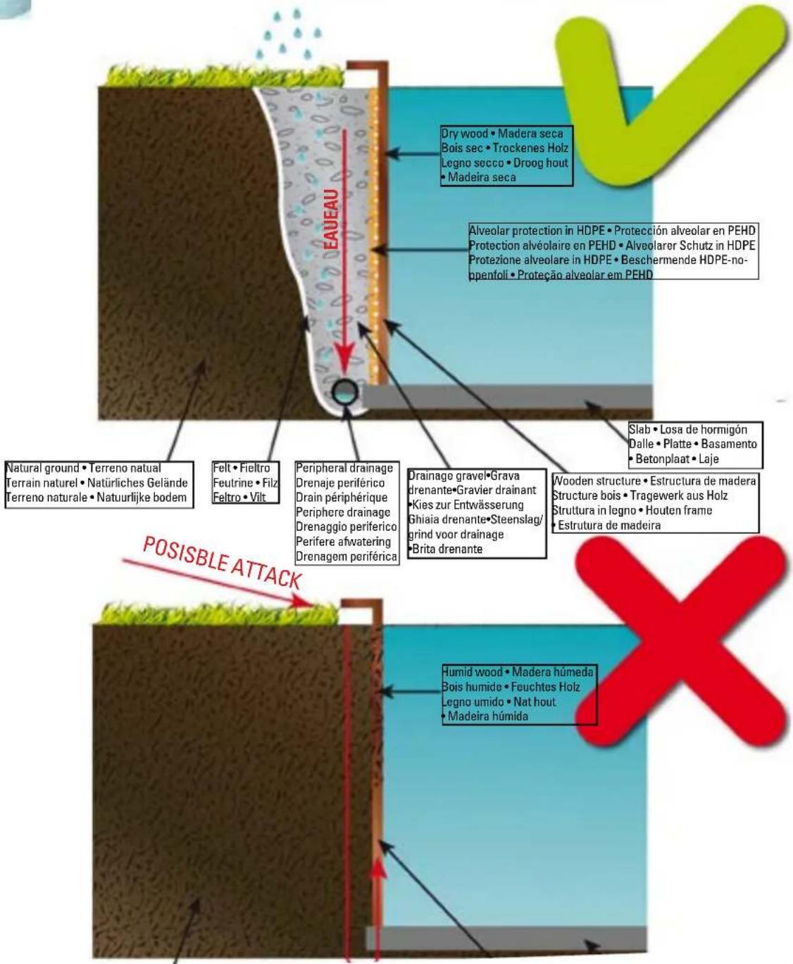
Natural ground • Terreno natural
Terrain naturel • Natürliches Gelände
Terreno naturale • Natuurlijke bodem
Wooden structure • Estructura de madera
Structure bois • Tragewerk aus Holz
Struttura in legno • Houten frame
Estrutura de madeira
Slab • Losa de hormigón
Dalle • Platte • Basamento
- Betonplaat • Laje
POSITIONING OF THE SEALING PIECES

natural_image
Close-up of a hand using a tool to apply white material to a circular object (no visible text or symbols)
natural_image
Close-up of hands using a tool to spread a white cylindrical object (no text or symbols visible)
natural_image
Close-up of two hands holding a small object, possibly a tool or wire (no text or symbols visible)
natural_image
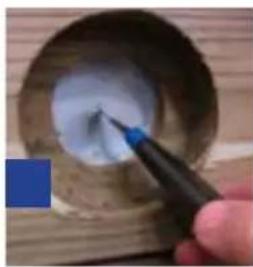
Two colored circles, one blue and one beige, on a plain white background (no text or symbols)REFILLING FITTING WITH KEY
Start filling the pool with water, up to 4 cm. from the lower edge of the valve hole.
Mark the hole with a felt tip pen (A) and cut a cross in the centre of the opening (B) with a cutter (BLADE), without going over the hole of the die cut.
From inside the pool, insert through the cut (C), the return valve (No. 1) with one of the friction rings (No. 2) and one of the seals (No. 3). The pieces of liner that stick out through the outer part of the pool, should be cut cleanly and accurately.
The other gasket (No 3.1) is placed from the outside, folding it, so that it is in contact with the liner and the panel.
Place the other friction ring (No 3.1) and tighten firmly with the nut. Thread the connector tube previously prepared with Teflon into the body of the nozzle, from outside of the pool.
Insert the return hose which goes from the outlet of the treatment unit to the return valve, and secure it with the clamp.
Important: Before placing the hose, insert the trim. (No 5)
Make sure that the filter apparatus valve is in the CLOSED position.
Look for us in our YouTube channel to help you with the assembly.
You
Tube

Install the filter before continuing with cutting the liner.
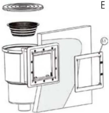
SKIMMER
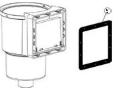
ASSEMBLING THE SKIMMER
Before installing the skimmer to the pool, the gate unit must be installed in the skimmer opening.
Then place the seal (No. 5) as indicated in A
ANCHORING THE SKIMMER
Continue filling the pool with water until it reaches a level of 4 cm. under the die-cut of the skimmer of the pool wooden.
Cut the liner using the cutter (blade) following the line of the die cut.
SKIMMER
EN
ABC
natural_image
Technical line drawing of a mechanical component with a separate view showing a square frame and a circular housing (no text or symbols)
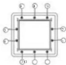
flowchart
graph TD
    A["①"] --> B["Square"]
    C["②"] --> B
    D["③"] --> B
    E["④"] --> B
    F["⑤"] --> B
    G["⑥"] --> B
    H["⑦"] --> B
    I["⑧"] --> B
    J["⑨"] --> B
    K["⑩"] --> B
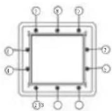
- Before continuing, make sure that the skimmer flap is well positioned.
- Mark the position of the fixing screws on the liner with a felt-tip pen.
• (B) Position the second square flat seal (5.1) and the flange (6) against the liner, aligning the holes with the position marks of the screws. - Fix the flange (6) on the liner with 10 screws (7) starting at the bottom(C). The pressure of fixing points on the liner should be constant, (fixing in cross
- Screw slightly at first to make sure they fit properly, then fully tighten them, following the order indicated in (C)
- Press on the trim cover No. 6.1, taking care to place the level mark in the correct position (D).
- Use Teflon to bolt the hose adapter (11) to the lower hole of the skimmer body, and then connect the suction hose and tighten with a clamp. (E)
- Cut the liner with a cutter from the inside of the skimmer.
- Now you should install the filter.
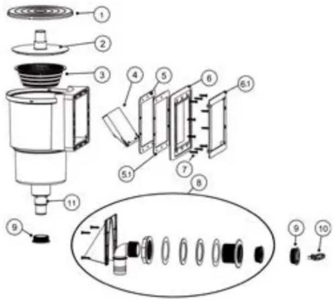
1- Skimmer cover
2- Suction cover
3- Basket
4- Gate unit
5- Adhesive joint
6- Flange 6.1- with trim cover
7- Bag of screws (2 DIN 7981 4,2X16 and 10DIN 7983 4,8X25)
8- Retum valve
9- Winter storage plug
10- Key
11- Hose adapter
Look for us in our YouTube channel to help you with the assembly.

D
natural_image
Technical line drawing of a mechanical device with labeled component E (no text or symbols beyond label)E
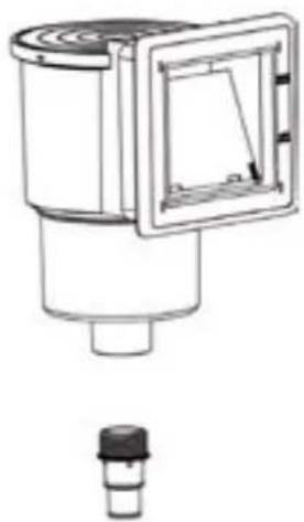
natural_image
Technical line drawing of a mechanical component with a square frame and a small cylindrical base (no text or symbols)
natural_image
Close-up of a hand using a pen to apply white substance into a wooden bowl (no text or symbols visible)
natural_image
Close-up of hands using a tool to apply material to a white cylindrical component (no text or symbols visible)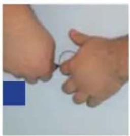
natural_image
Close-up of two hands holding a small object, possibly a wire or tool, against a plain background (no text or symbols visible)
natural_image
Two small objects on a plain background: a blue square and a beige circle (no text or symbols)natural_image
Technical line drawing of a mechanical component with a separate view showing a square frame and a circular housing (no text or symbols)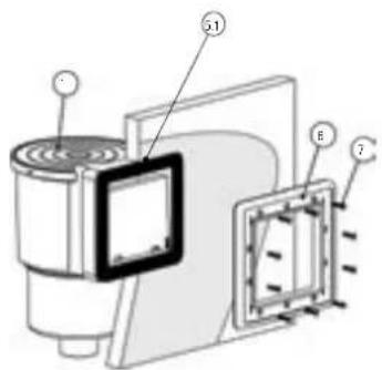
flowchart
graph TD
    A["1"] --> B["2"]
    C["3"] --> D["4"]
    E["5"] --> F["6"]
    G["8"] --> H["9"]
    I["10"] --> J["11"]
    K["12"] --> L["13"]
natural_image
Technical line drawing of a mechanical device with labeled parts (no text or symbols present)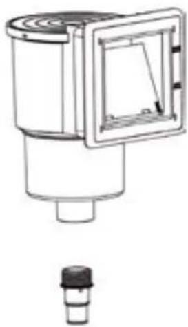
natural_image
Technical line drawing of a mechanical component with a square frame and a small cylindrical base (no text or symbols)FR
natural_image
Close-up of a hand using a tool to apply blue liquid onto a circular object (no text or symbols visible)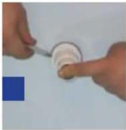
natural_image
Close-up of hands using a tool to dispense a white cylindrical object onto a surface (no text or symbols visible)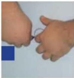
natural_image
Close-up of two hands holding a small object, possibly a wire or tool, against a plain background (no text or symbols visible)
natural_image
Two small objects on a plain background: a blue square and a light orange circle (no text or symbols)BUSE DE REFOULEMENT
natural_image
Technical line drawing of a mechanical component with a separate view showing a square frame and a circular housing (no text or symbols)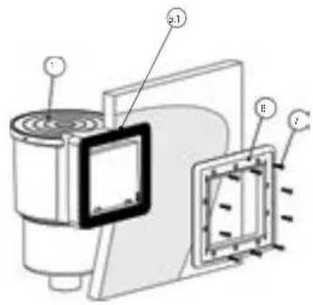
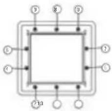
flowchart
graph TD
    A["①"] --> B["Square"]
    C["②"] --> B
    D["③"] --> B
    E["④"] --> B
    F["⑤"] --> B
    G["⑥"] --> B
    H["⑦"] --> B
    I["⑧"] --> B
    J["⑨"] --> B
    K["⑩"] --> B
    L["⑪"] --> B
    M["⑫"] --> B
    N["⑬"] --> B
    O["⑭"] --> B
    P["⑮"] --> B
    Q["⑯"] --> B
    R["⑰"] --> B
    S["⑱"] --> B
    T["⑲"] --> B
    U["⑳"] --> B
    V["㉑"] --> B
natural_image
Technical line drawing of a mechanical device with labeled parts (no readable text or symbols)E
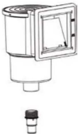
natural_image
Technical line drawing of a mechanical component with a square frame and a small cap (no text or symbols)natural_image
Technical line drawing of a mechanical component with a separate view showing a square frame and a circular housing (no text or symbols)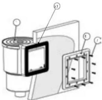
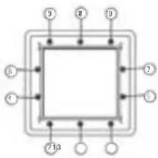
D
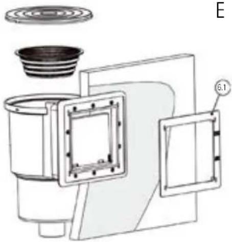
natural_image
Technical line drawing of a mechanical device with labeled parts (no text or symbols present)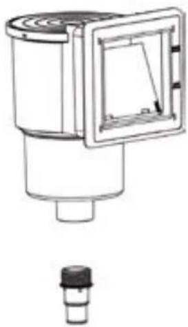
natural_image
Technical line drawing of a mechanical component with a square frame and a small cylindrical base (no text or symbols)natural_image
Close-up of a hand using a tool to apply blue ink on a wooden surface (no text or symbols visible)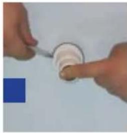
natural_image
Close-up of hands using a tool to apply material to a white cylindrical component (no text or symbols visible)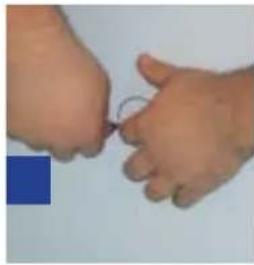
natural_image
Close-up of two hands holding a small object, possibly a tool or wire (no text or symbols visible)
natural_image
Two small objects on a plain background: a blue square and a light orange circle (no text or symbols)UGELLO DI MANDATA
natural_image
Technical line drawing of a mechanical component with a separate view showing a square frame and a circular housing (no text or symbols)
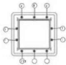
D
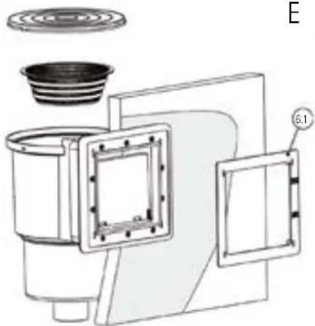
natural_image
Technical line drawing of a mechanical device with labeled components (no readable text or symbols)E
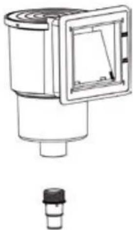
natural_image
Technical line drawing of a mechanical component with a square frame and a small cap (no text or symbols)natural_image
Close-up of a hand using a tool to apply white material to a small bowl (no text or symbols visible)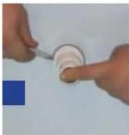
natural_image
Close-up of hands using a tool to apply material to a white cylindrical component (no text or symbols visible)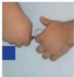
natural_image
Close-up of two hands holding a small object, possibly a tool or wire (no text or symbols visible)
natural_image
Two small objects on a plain background: a blue square and an orange circle (no text or symbols)UITSTROOMMONDSTUK
natural_image
Technical diagram of a mechanical component with labeled section A and part 5, showing internal structure and mounting detail (no text or symbols beyond labels)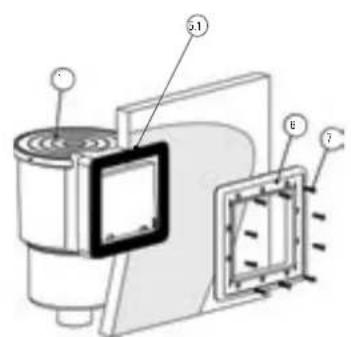
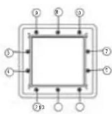
natural_image
Technical line drawing of a mechanical device with labeled component (E), showing internal components and mounting features (no text or symbols beyond label)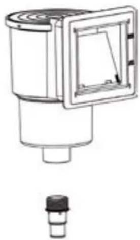
natural_image
Technical line drawing of a mechanical component with a square frame and a small cylindrical base (no text or symbols)natural_image
Close-up of a hand using a tool to apply white material to a circular object (no text or symbols visible)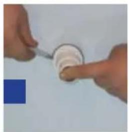
natural_image
Close-up of hands using a tool to apply material to a circular component (no visible text or symbols)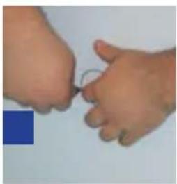
natural_image
Close-up of two hands holding a small object, possibly a tool or wire (no text or symbols visible)
natural_image
Two small colored circles on a plain background: a blue square and a light orange circle (no text or symbols)natural_image
Technical line drawing of a mechanical component with a separate view showing a square frame and a circular housing (no text or symbols)

flowchart
graph TD
    A["①"] --> B["Square"]
    C["②"] --> B
    D["③"] --> B
    E["④"] --> B
    F["⑤"] --> B
    G["⑥"] --> B
    H["⑦"] --> B
    I["⑧"] --> B
    J["⑨"] --> B
D
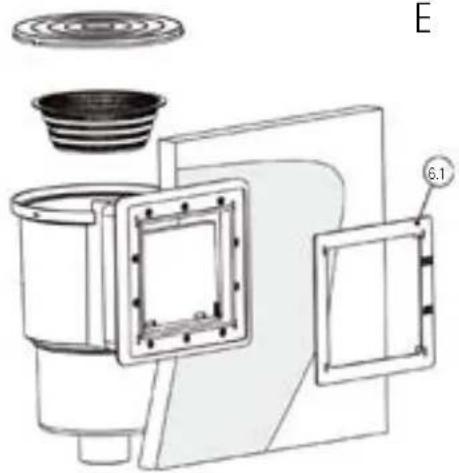
natural_image
Technical line drawing of a mechanical device with labeled parts (no text or symbols present)E
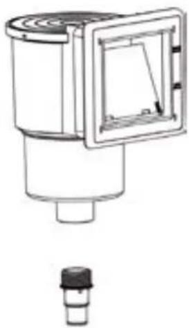
natural_image
Technical line drawing of a mechanical component with a square frame and a small cylindrical base (no text or symbols)ASSEMBLY SUGGESTIONS: • The filter should be located at least 3.50 m from the pool.
The following diagrams explain the movement direction of the water. Check the manual that comes with the filter group for the assembly instructions. Note: Fill the filter with 2/3 of clean, calibrated sand: only one calibration is supplied guaranteeing good use of the filer. (1) The colours and connections of the filter can vary according to models. Check the specific manual
The multi-directional flap determines the flow direction. The marks "PUMP", "RETURN", "WASTE" are engraved on the inlets and outlets of the pump. The installation of all the electrical systems should comply with the NF-C15-100 regulation. Check with the manufacturer for any modification of one or several filter system components. The suction pump should not be situated above the water level, because there is a risk of becoming deactivated.
All the threaded connections should be assembled with the watertight Teflon tape included *, except the connection with O rings. The Teflon should be wound round the thread in a counter clockwise direction.
LAND-FILLING: Finish filling the pool The water level should be situated between the upper third part and the second half of the skimmer mouth.
EN This is the oldest of filtering systems. The filtered water passes through the sand (calibrated silicon) that retains all impurities. This type of filter is equipped with a multi-directional flap that allows easy manipulations and cleaning.
DIFFERENT POSITIONS OF THE MULTI-DIRECTIONAL FLAP (4 OR 6)*: When you perform changes the position of the multi-directional flap that pump should always be stopped, without risking seriously damaging the filter and cancelling the guarantee.
- FILTERING POSITION (OR FILTER): Usual position of the flap that allows the water coming from the pump to enter through the upper part of the filter and circulate through the sane, where all its impurities are trapped. The water is collected in the mesh at the bottom and returned to the pool. The pressure gauge situated at the upper part of the filter allows controlling the pressure. In the case that the pressure increase 0.2 bar regarding the starting pressure, you will need to clean the filter.
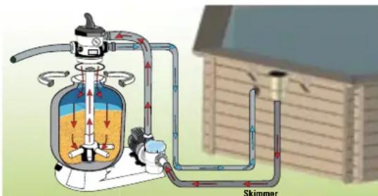
EN 2. WASHING POSITION (OR BACKWASH): Sand washing position. Allow the water to circulate in reverse direction in the filter. The water enters through the lower part of the filter elevates the filtering mass and therefore collects all its impurities and because they are lighter than sand, they area evacuated through the upper part of the filter towards the drain. This operation should last between 2 and 3 minutes.
ES 2. POSICIÓN LAVADO (O BACKWASH): Posición de limpieza de la arena. Permite que el agua circule en sentido inverso en el filtro. El agua entra por la parte inferior del filtro y hace que se levante la masa filtrante y por lo tanto se recojan sus impurezas que, al ser más ligeras que la arena, se evacuan por la parte alta del filtro hacia el desagüe. Esta operación deberá durar entre 2 y 3 minutos.
2. POSITION LAVAGE (OU BACKWASH) : Position de nettoyage du sable. Elle permet de faire circuler l'eau en sens inverse dans le filtre. L'eau entre par le bas du filtre et vient soulever la masse filtrante et ainsi débarrasser de ses impuretés qui, plus légères que le sable, sont évacuées par le haut du filtre vers l'égout. Cette opération devra se faire pendant 2 à 3 minutes.
DE 2. POSITION RÜCKSPÜLEN (ODER BACKWASH): Position der Reinigung des Sandes. Ermöglicht, dass das Wasser in umgekehrter Richtung in den Filter fließt. Das Wasser tritt durch das untere Teil des Filters ein und sorgt dafür, dass die Filtermasse steigt und folglich seine Verunreinigungen gesammelt werden, die durch das obere Teil des Filters Richtung Abfluss entsorgt werden, da sie leichter sind als der Sand. Dieser Vorgang muss 2 bis 3 Minuten dauern.
2. POSIZIONE LAVAGGIO (O BACKWASH): Posizione di pulizia della sabbia. Permette che l'acqua circoli nel senso contrario nel filtro. L'acqua entra nella parte inferiore del filtro e fa sollevare la massa filtrante e quindi le impurità si raccolgono, essendo più leggere della sabbia, ed escono dalla parte alta del filtro fino allo scarico. Questa operazione ha una durata di 2-3 minuti.
NL 2. STAND WASSEN (OF BACKWASH): Stand voor schoonmaken van het zand. Zorgt ervoor dat het water in omgekeerde richting door het filter circuleert. Het water komt binnen via de onderkant van het filter en dit zorgt ervoor dat de gefilterde vuil omhoog komt waardoor de onzuiverheden die veel lichter zijn dan het zand worden verzameld en via het bovenste deel kunnen worden afgevoerd naar de waterafvoer. Deze handeling zou tussen de 2 en 3 minuten moeten duren.
2. POSIÇÃO LAVAGEM (OU BACKWASH): Posição de limpeza da areia. Permite que a água circule em sentido inverso no filtro. A água entra pela parte inferior do filtro e faz com que a massa filtrante se levante e, portanto, com que sejam recolhidas as suas impurezas, que, sendo mais leves do que a areia, são evacuadas pela parte alta do filtro para o esgoto. Esta operação deverá durar entre 2 e 3 minutos.
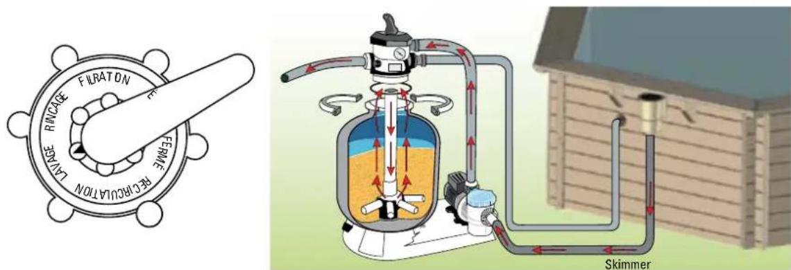
EN 3. RINSE POSITION / DRAINING OF THE FILER** (OR RINSE): Operation that follows washing the filter. When you have cleaned the filter, you should rinse and re-compress the filtering mass. In this position the water circulates through the filter as in the filtering position but is evacuated through the drain at the filter outlet. This operation should be performed between 20 and 30 seconds.
ES 3. POSICIÓN ACLARADO / DESAGÜE DEL FILTRO** (O RINSE): Operación que sigue al lavado del filtro. Cuando se ha limpiado el filtro, es imprescindible aclarar y volver a apretar la masa filtrante. En esta posición el agua circula por el filtro como durante la filtración pero se evacua por el desagüe en la salida del filtro. Esta operación se debe efectuar entre 20 y 30 segundos.
3. POSITION RINÇAGE / FILTRE ÉGOUT** (OU RINSE) : Opération qui suit le lavage du filtre. Lorsque le filtre a été nettoyé, il est indispensable de rincer et de retasser la masse filtrante. Dans cette position, l'eau chemine dans le filtre comme en filtration mais est évacuée à l'égout en sortie du filtre. Cette opération devra se faire pendant 20 à 30 secondes.
DE 3. POSITION AUSSPÜLEN / DRAINAGE DES FILTERS** (ODER RINSE): Vorgang, der auf die Reinigung des Filters folgt. Wenn der Filter gesäubert worden ist, muss er ausgespült und die Filtermasse erneut festgedrückt werden. In dieser Position fließt das Wasser durch den Filter wie während der Filtration, doch am Filterausgang wird es durch den Abfluss abtransportiert. Dieser Vorgang muss 20 bis 30 Sekunden durchgeführt werden.
IT 3. POSIZONE CHIARIFICAZIONE/SCARICO DEL FILTRO** (O RINSE): Operazione che segue il lavaggio del filtro. Dopo aver pulito il filtro, è necessario chiarificare e comprimere la massa filtrante. In questa posizione l'acqua circola per il filtro come durante la filtrazione però esce tramite lo scarico all'uscita del filtro. Questa operazione ha una durata di 20-30 secondi.
NL 3. STAND TERUGSPOELEN / AFVOEREN VAN HET FILTER** (OF RINSE): Handeling die volgt op het wassen van het filter. Wanneer het filter is gewassen, is het van het grootste belang dat het gefilterde vuil wordt nagewassen en het filtervuil wordt verzameld. In deze stand circuleert het water door het filter zoals tijdens het filteren maar gaat naar buiten via de afvoer in de uitlaat van het filter. Deze handeling moet tussen de 20 en 30 seconden worden uitgevoerd.
PT 3. POSIÇÃO ENXAGUADELA / ESCOAMENTO DO FILTRO ** (OU RINSE): Operação que se segue à lavagem do filtro. Quando o filtro já foi limpo, é imprescindível enxaguar e apertar novamente a massa filtrante. Nesta posição, a água circula pelo filtro como durante a filtração, mas evacua-se pelo esgoto na saída do filtro. Esta operação deve ser efetuada entre 20 e 30 segundos.
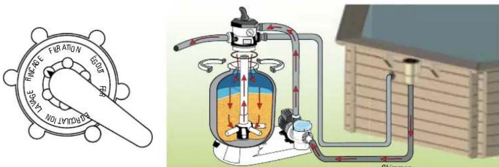
EN 4. EMPTYING POSITION / DRAIN (OR WASTE): Position to evacuate the water of for emptying the pool. In this case, the water does not pass through the filter, it goes directly to the drain.
ES 4. POSICIÓN VACIADO / DESAGÜE (O WASTE): Posición para evacuar el agua o para vaciar el vaso. En este caso, el agua no pasa por el filtro, sale directamente por el desagüe.
4. POSITION VIDANGE / ÉGOUT (OU WASTE): Position pour évacuer l'eau ou vidanger le bassin. Dans ce cas, l'eau ne passe pas par le filtre, elle est évacuée directement à l'égout.
DE 4. POSITION LEEREN / ABFLUSS (ODER WASTE): Position, in der das Wasser abgelassen oder das Becken entleert wird. In diesem Fall fließt das Wasser nicht durch den Filter, sondern direkt durch den Abfluss.
IT 4. POSIZIONE SVUOTAMENTO / SCARICO (O WASTE): Posizione per far uscire l'acqua o per svuotare la vasca. In questo caso, l'acqua non passa per il filtro, esce direttamente dallo scarico.
NL 4. STAND LOZEN / WATERAFVOER (OF WASTE): Stand voor de afvoer van water of om het bassin leeg te laten lopen. In dit geval passeert het water niet door het filter, maar gaat meteen naar de waterafvoer.
PT 4. POSIÇÃO ESVAZIAMENTO / ESCOAMENTO (OU WASTE): Posição para evacuar a água ou para esvaziar o tanque. Nesse caso, a água não passa pelo filtro, sai diretamente pelo esgoto.
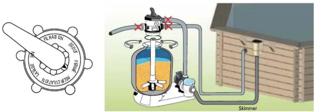
EN 5. CLOSED POSITION (OR CLOSED): This position does not allow the water to pass and is used to put the pool into complete wintering when the filtering stops.
ES 5. POSICIÓN CERRADA (O CLOSED): Esta posición no permite que el agua pase y se utiliza para poner la piscina en invernaje completo cuando se detiene la filtración.
5. POSITION FERMÉE (OU CLOSED) : Cette position ne permet aucun passage d'eau et est utilisée pour mettre la piscine en hivernage complet lorsque l'on arrête la filtration.
DE 5. POSITION GESCHLOSSEN (ODER CLOSED): Diese Position verhindert, dass Wasser durchfließt, und wird für die komplette Überwinterung des Pools verwendet, wenn die Filtration gestoppt wird.
IT 5. POSIZIONE CHUSA (O CLOSED): Questa posizione non permette all'acqua di passare e si utilizza per mettere la piscina in invernaggio completo quando si ferma la filtrazione.
NL 5. STAND GESLOTEN (OF CLOSED): Deze stand voorkomt dat het water passeert; deze stand wordt gebruikt om het zwembad totaal winterklaar te maken wanneer de filtering wordt gestopt.
PT 5. POSIÇÃO FECHADA (OU CLOSED): Esta posição não permite que a água passe e é utilizada para colocar a piscina em hibernação completa quando a filtração é detida.

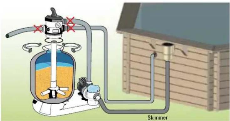
EN 6. RECIRCULATION POSITION / CIRCULATION**: Position used so the water circulates through the hydraulic network without passing through the filter. This possibility is used to move the water if you want to add a product to the pool or if you should perform any operation in the filter, because in this case the filter is isolated and the water coming from the pump is directly expelled.
* Some models are delivered with 4-way flap (available options: Filtering, Washing, Emptying/drain Closed or wintering).
** These positions refer exclusively to the 6-way flap.
You should never manoeuvre the multi-directional flap when the pump is working.
EN EDGES: the edge consists of 2 pieces, an inside one and an outside one. Check the drawings (See page 42-43).
PREPARATION
- Before fixing the edge, position all the pieces as a trial, checking the installation drawings at the end of the manual, without screwing them, to uniformly distribute the sets.
- Let the edge overlap towards the inside to create a «breakwater».
FIXING
- You should previously drill the edges with a 0.4mm bit for wood to obtain a firm and long-lasting fixing. Use 0.4× 60mm stainless steel screws for the assembly, these should be obliquely screwed in (in the case of the exterior ones) to the bottom of the slits.
- When all the edges have been adjusted, continue with levelling the blocks of wood.
natural_image
Close-up of a corrugated metal structure with vertical rods and four black nail pins (no text or symbols visible)Fixing of the edges Colocación de las playas Fixation des margelles Befestigung der Ränder Fissaggio dei bordi Bevestiging van de randen Fixação dos bordos
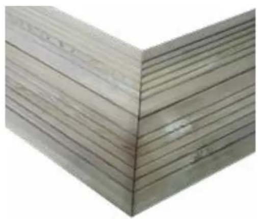
natural_image
Stack of wooden slats arranged in a V-shape (no text or symbols visible)Fixing of the edges Colocación de las playas Position des margelles Positionierung der Ränder Posizionamento dei bordii Plaatsing van de randen Colocação dos bordos
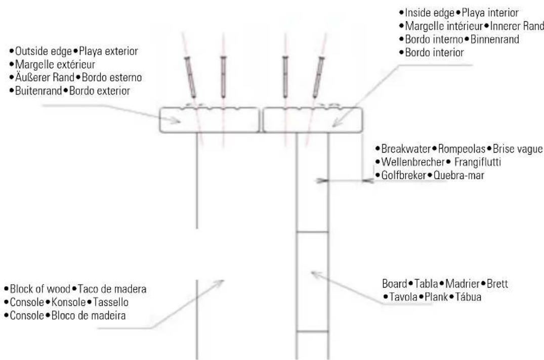
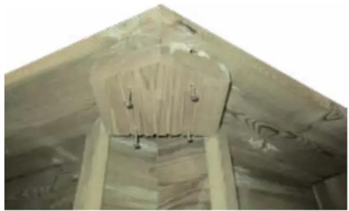
natural_image
Interior ceiling view of a building with exposed structural beams and fixtures (no text or symbols visible)Fixing of the plates
Fijación de los tacos bajo las placas
Fixation de la plaque sous margelles
Befestigung der Platten unter den Rändern
Fissaggio delle piastre sotto i bordi
Bevestiging van de platen onder de randen
Fixação das placas sob os bordos
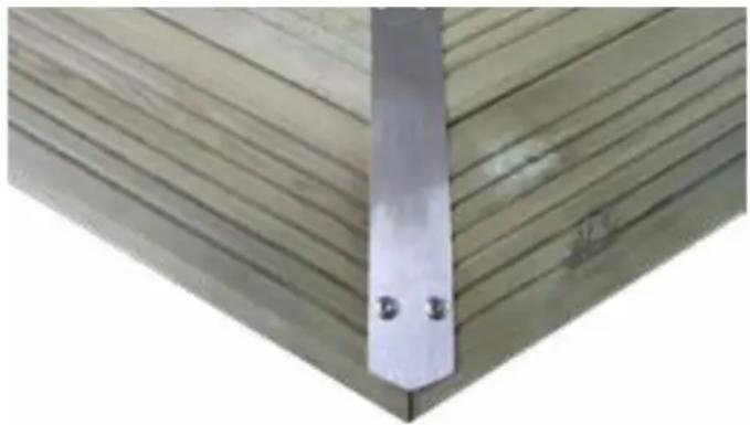
natural_image
Close-up of a metal bracket with two small holes, mounted on a wooden deck (no text or symbols visible)Fixing of the corner trimmings
Colocación de los embellecedores de esquinas
Position des cache-angles
Positionierung der Zierleisten für die Ecken
Posizionamento della coperture degli angoli
Plaatsing van de sierlijsten voor hoeken
Colocação dos embelezadores de esquinas
EN PIECE UNDER THE EDGES: position the pieces of wood under the edges at the angles and fix them with 4 screws (4x40). CORNER TRIMMING
- To improve the aesthetics of the edges, you will find corner trimmings together with your pool.
- The stainless steel trimmings are fixed by means of 4 round-head screws (6x30).
natural_image
Black-and-white photo of a wooden table with a white cylindrical object and a metal tool, no visible text or symbols.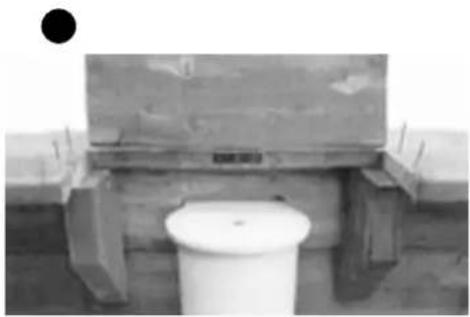
natural_image
Exterior view of a concrete structure with a white cylindrical container on a wooden platform (no visible text or symbols)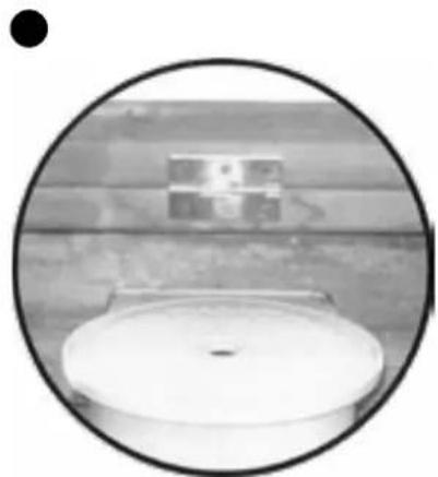
natural_image
Circular cropped photo of a white toilet with a small rectangular object on the wall, set against a wooden surface (no text or symbols visible)EN SKIMMER ACCESS EDGE
- In the panel where the skimmer is located, cut only the outer edge with a measure corresponding to the distance between the blocks (image 1). The hatch should be midway between the consoles (image 2).
- Secure the skimmer access hatch with the hinge included.
- To fit the hinge, place the hatch against the interior edge.
ES PLAYA ACCESO SKIMMER
- Assemble the upper handrail (1) and lower (7) introducing one into the other (figure 20). Fix the steps (6) into the handrails using the bolts (8), the washers (4) and the nuts (9).
- Position plugs (10) into the handrails to avoid the stepladder damaging the wall of the pool.
- When you have assembled the stepladder, place it on the edge with the handrail support (5) as a template
- Fix the handrail supports (5) using the screws (3) and the washers (4) (figure 21).
Insert the trimmings (2).

EN A salt filter can cause degradation of your stainless steel stepladder and this is not covered by the guarantee.
Do not use the stepladder for other needs different to those indicated in this manual. Admitted maximum weight: 150 kg.
During the first use, you should wash the filter (check the filer system maintenance). Filtering is a mechanical treatment that allows cleaning the pool water by means of eliminating the impurities and contaminating particles. The hydraulic circuit and water purifying group is an essential element for the optimal operation of the filtering system. The filtering system should be coherent: The filter dimensions should be proportionate to the volume of water in the pool and to the pump performance. The filtering is not anti-bacteria. Therefore, you should add a product (or a system) for disinfection of the water.
FILTERING TIME:
During the period of use of the pool kit, the filtering system should be used every day, for sufficient time to guarantee a complete renovation of the entire volume of water. Theoretically, this the calculation:
(Water Temp / 2) = equals the filtering hours
Often, it is more practical to filter 4 hours before and 4 hours after use.
We do not recommend intermittent operation (stopping and starting every hour) because not all the water volume will be renovated.
OPERATION PRINCIPLE:

The skimmer sucks the water from your pool (this element and especially the basket that collects leaves and other large impurities, should be very clean).
The water is then sent through the tubes to reach a pump with pre-filter * (there another basket filters medium impurities, therefore its cleanliness is essential for good operation).
| 15 to 18°C 8 hours | |
| 19 to 21°C 10 hours | |
| 22 to 25°C 12 hours | |
| 26 to 28°C 14 hours | |
| 28 to 30°C 19 hours | |
| + than 30°C 24 hours |
The pump sends the water towards a filter that retains all the suspended impurities thanks to its filtering material. This is a sand filter. The filtered water returns to the pool. This unit can be manipulated, programmed and protected using an electrical unit (optional).
The water from your pool should be subject to physical and chemical treatment to keep its transparency and to guarantee a completely safe bath.
We do not recommend filling to the pool with well water, to avoid all types of chemical reaction and water colouring risks.
- The water level is correct: that is to say, slightly above half of the skimmer.
- The skimmer and pump pre-filer baskets are clean.
- The hydraulic circuit is controlled and the flap positions verified.
- The filter can be started and the pressure controlled with a pressure gauge (according to the type and the position of the technical location regarding the pool).
HAVING ACCESS TO THE POOL IS PROHIBITED IN THE CASE THAT THE FILTER SYSTEM IS DETERIORATED
* According to model
MAINTENANCE OF THE FILTERING SYSTEM
CLEANING THE FILTER
Perform this procedure each time you need to clean the filter. When the pressure increases 0.2 bar regarding the starting pressure you need to clean as follows. Make sure that you have correctly installed the emptying tube (not included) in the collector of the multi-directional flap, so that it allows water evacuation when the sand or filer is cleaned.
-
Stop the filtering.
-
Put the multi-directional flap to the WASH position.
-
Start the filter and let it work for at least 2 to 3 minutes.
-
Stop the filtering again, put the multi-directional flap into RINSE position and re-start the filter for 10 seconds.
-
Stop the filer and put the multi-directional flap into FILTERING position.
-
Re-start the filter and check that the pressure is correct.
CLEANING THE POOL
With a manual pool cleaner
- Connect the pool cleaner tube
- Introduce the pool cleaner into the water
- Fill the tube with water placing it before the refilling fitting with key.
- Place the other end in the pool cleaner outlet.
- You should slowly move the pool cleaner (to avoid moving the dust) and without taking it out of the water, to avoid deactivating the pump.
- When you have finished the cleaning, clean the filter before putting it into its normal position.
RECOMMENDATIONS:
- You should check that the suction holes are not blocked.
- You should stop the filtering during the maintenance operations of the filtering system.
- Periodically check the greasing level of the filter.

Maintenance and wintering of the filter requires water evacuation. The evacuation should be foreseen when installing the filter group.
WATER TREATMENT
Whichever is your filtering system, you will need to chemically treat the pool water to destroy the bacteria and the micro-bodies and to avoid development of algae.
Several sterilization products can be used, like chloride, bromine, oxygen, etc. Request the assessment of a pool treatment product sales person to take a decision.
First, you have to verify the pH level using an analysis kit. Pay attention that the test bottles are only valid for one year.
The ideal level is between 7.2 and 7.4 of pH and 1.5 regarding CHLORIDE. Rectify this level using pH correctors (increasers or reducers). The quantity of product is proportional to the cubic meters of your pools. To treat your pool, check the indications appearing on the product you have chosen for your pool.
pH (potential hydrogen) You should always maintain the water pH between 7.2 and 7.4 because below these values the water becomes corrosive (due to acidity)

and rapidly deteriorates the metal parts of your pool. Above these values the water is basic and greatly reduces the action of treatment. Never introduce chlorine tablets directly into the pool. The liner would be «burnt».
SAFETY SUGGESTIONS
Carefully read, understand, and follow all information in this user manual before installing and using the swimming pool.
These warnings, instructions, and safety guidelines address some common risks of water recreation, but they cannot cover all risks and dangers in all cases. Always use caution, common sense, and good judgment when enjoying any water activity. Retain this information for future use.
When your pool reaches the end of its useful life, it should be disassembled; the different materials (plastic and steel) should be separated and taken to the disposal point indicated by local authorities.
Non Swimmers safety
Continuous, active, and vigilant supervision of weak swimmers and non-swimmers by a competent adult is required at all times (remembering that children under five are at the highest risk of drowning).
- Designate a competent adult to supervise the pool each time it is being used.
- Weak swimmers or non-swimmers should wear personal protection equipment when using the pool.
- When the pool is not in use, or unsupervised, remove all toys from the swimming pool and its surrounding to avoid attracting children to the pool.
Safety devices
- It is recommended to install a barrier (and secure all doors and windows, where applicable) to prevent unauthorized access to the swimming pool.
- Barriers, pool covers, pool alarms, or similar safety devices are helpful aids, but they are not substitutes for continuous and competent adult supervision.
Safety equipment
- It is recommended to keep rescue equipment (e.g. a ring buoy) by the pool.
- Keep a working phone and a list of emergency phone numbers near the pool.
Safe use of the pool
- Encourage all users especially children to learn how to swim
- Learn Basic Life Support (Cardiopulmonary Resuscitation - CPR) and refresh this knowledge regularly.
This can make a life-saving difference in the event of an emergency. - Instruct all pool users, including children, what to do in case of an emergency
-Never dive into any shallow body of water. This can lead to serious injury or death. - Do not use the swimming pool when using alcohol or medication that may impair your ability to safely use the pool.
- When pool covers are used, remove them completely from the water surface before entering the pool.
- Store chemicals (e.g. water treatment, cleaning or disinfection products) out of the reach of children.
- Signage is to be displayed in a prominent position within 2 m of the pool.
- Removable ladders shall be placed on a horizontal surface.
- Protect pool occupants from water related illnesses by keeping the pool water treated and practicing good hygiene. Consult the water treatment guidelines in the user's manual.
WARNING:
Every electrical appliance fed in 220 V, has to be located at least at 3.50 m from the edge of the pool.
The equipment should be connected to a voltage, with earth connection, protected by a residual current device (RCD) having a rated residual operating current not exceeding 30 mA.
Read the instructions carefully and keep for future reference.
IF YOU HAVE ANY PROBLEM, ..;CONTACT US!
CONTACT:
web: www.service-gre.com

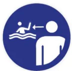
natural_image
Blue circular icon showing a person swimming and standing with an arrow indicating water movement (no text or symbols)
natural_image
Blue circular icon with a white human figure silhouette (no text or symbols)
natural_image
Blue circular sign with a crossed-out airplane and wave symbol (no text)PUESTA EN SERVICIO
natural_image
Blue circular icon showing a person swimming and standing on water, with an arrow indicating direction (no text or symbols)
natural_image
Blue circular icon with a white human figure silhouette (no text or symbols)
natural_image
Blue circular sign with a crossed-out airplane and wave symbol (no text)MISE EN SERVICE
natural_image
Blue circular icon showing a person swimming with an arrow indicating water movement (no text or symbols)
natural_image
Blue circular icon with a white human figure silhouette (no text or symbols)
natural_image
Blue circular sign with a crossed-out airplane and wave symbol (no text)INBETRIEBNAHME
natural_image
Blue circular icon showing a person swimming with an arrow indicating water movement (no text or symbols)
natural_image
Blue circular icon with a white human figure silhouette (no text or symbols)
natural_image
Blue circular sign with a crossed-out pictogram of a person crossing water, no text or symbols present.MESSA IN SERVIZIO
natural_image
Blue circular icon showing a person swimming with a stick and arrow, no text or symbols present.
natural_image
Blue circular icon with a white human figure holding a rectangular object (no text or symbols)
natural_image
Blue circular sign with a crossed-out airplane and wave symbol (no text)INGEBRUIKNAME
natural_image
Blue circular icon showing a person swimming with a wave and a person walking, no text or symbols present.
natural_image
Blue circular icon with a white human figure silhouette (no text or symbols)
natural_image
Blue circular sign with a crossed-out blue symbol and wave pattern below (no text)natural_image
Blue circular icon depicting a person swimming with a wave and a person walking, no text or symbols present.
natural_image
Blue circular icon with a white human figure silhouette (no text or symbols)
natural_image
Blue prohibition sign with crossed-out fish and wave symbols (no text)NORMAL MAINTENANCE
RESPECT THE ENVIRONMENT
DO NOT TAKE APART THE POOL UNLESS IT IS STRICTLY NECESSARY. IF YOU DO SO, PLEASE REUSE THE WATER. WATER IS A SCARCE GOOD.
MAINTENANCE AND USE:
- Switch on the filter system once a day in to insure a complete water volume renewal and never do it when somebody is in the pool (see filter manual).
- Check the filter's level of clogging regularly in summer when the pool kit is in use.
- Check screws, nuts and washers (for rust).
- The pool water level has always to be hold in a minimum of 15 cm from the pool superior edge.
- Never empty the pool completely. Low water levels may cause serious damage to the pool.
- Failure to comply with the maintenance instructions may lead to serious health risks, especially for children.
- The use of a swimming costume entails respect for the safety regulations set out in the maintenance and user guide.
- Never leave a pool kit empty on the ground, outdoors.
- Clean regularly the P.V.C liner and the water level mark with non-abrasive products. Regularly clean the fold joining the bottom to the side of the liner, as it is an area where
dirt accumulates. If you do by accident a small hole in the liner, you can repair it thanks to our rubber patches AR202 or V12. - The isothermic covers (for the summer) protect your pool from insects, dust, leaves,... and avoid to loose the water temperature. Do always set it in order the bubbles are in contact with the water.
WINTER-SEASON:
1- Clean the liner bottom and sides with a non-abrasive product.
2- Treat the water with a chemical product for wintering. We recommend using LIQUID WINTERISER instead of floats with solid product to avoid discolouring the liner.
3- Leave the pool full of water considering:
a) For pools with skimmer and refulling pipe, reduce the water level 5 cm underneath the skimmer and close the refulling pipe with the screw tap which is included with the filter.
b) For pools with exhaustion and refulling pipes, reduce the water level 20 cm from the superior edge of the pool and close the pipes using the screw system incorporated.
4- Disconnect the pipes. Do not dismount the skimmer and the refulling and exhaustion pipes.
5- Protect the pool with a winter cover, and put a floating element between the cover and the water, in order to protect it from frost.
6- Filter: disconnect it from the pool. Clean it, empty the sand or remove the cartridge, dry it and keep it in a covered and sheltered from dampness place.
7- Accessories: remove every accessories (ladder, alarm, spotlight, pole...), rinse them with soft water and tidy them away. TO RUN THE POOL AGAIN: Remove the winter cover, install the filter, change at least 1/3 of water and realize a chlorine treatment. Switch on the filter for at least 8
hours in an uninterrupted way, respecting the continuous working period indicated in the filter manuals.
CHIMICAL MEASURES:
Please read carefully the chemical product manufacturer instructions. WARNING: Keep chemical products in a clean, dry and out of children place. Important: Every products used have to be compatible with the P.V.C liner.
- First filling: Analyse the water pH and chlorine (Cl) and adjust them to the optimal levels: pH: 7,2–7,6; Chlorine: 0.5–2 ppm.
- Chlorine treatments: Consist in increasing the chlorine level until approximatively 20 ppm to eliminate germs and seaweeds. This process has to be done only when the pool water comes from rivers or ponds, ... or if it stayed a long time without any treatments.
- Checking: Check at least once a week the chlorine levels (use a chlorine and pH analyser). In the same way, we advise to add an algicid to prevent seaweeds appearance.
Never have a swim before the chlorine level stabilization. Do always use a floating dispenser for the chemical product (tablets) dissolution. The chemical product measuring out has to be done in accordance with: Your pool water volume, the bathe frequency, the climatic conditions, the water temperature and the location. Do always move the water and wait for the chemical product dissolution before adding another one. Wait approximatively 12 hours between any pH, chlorine or algicid adjustment using the filter
system.
MECHANICAL MEASURES:
Check the filter, the skimmer, the valves and the pipes are well connected to the pool. Do consider high water temperature will involved more time for the filtering. Theoretic filtering time = Water volume / Filter system discharge (generally 8h/day with water temperature of 21°C), (Ideal: 2h in the morning – 4h around midday – 2h in the afternoon). PLEASE RESPECT THE CONTINUOUS WORKING PERIOD INDICATED IN THE FILTER MANUALS.
VACUUM CLEANER (MANUAL OR AUTOMATIC):
Only for pools with skimmer. Connect an hose extremity to the brush head and immerse it into the water to make it fill in. Connect the other pipe extremity to the exhaustion adapter (TA) and place it above the skimmer basket. Switch on the filter in the FILTER position and begin to clean the bottom. Pay special attention to areas with folds where dirt accumulates.
BOTTOM CLEANER VENTURY STYLE:
Connect a garden hose to the bottom cleaner join and introduce it into the pool. Open the tap until a normal pressure to make the water flow out against the bottom of the pool, producing in that way an ascendant stream which leave the dirt into the filter (bag) which is adjust on the bottom cleaner.
| EFFECTS CAUSES SOLUTIONS | ||
| Cloudy waterGreen coloured | Dirty filterpH incorrectFormation of algae | Washing the filter.Re-adjustmentShock treatment |
| The pump does not start • Breaker discon | nectedFuse burntTurbine blocked | Re-startReplace itCheck that the fan at the rear of the motor turns |
| The pump turns but does not discharge • | Suction flaps closedThe skimmer sucks airPre-filter fullAir inlet in the coverDefective turbine | Open them againRectify water levelClean itCheck the seal and change the pre-fil-ter coverChange the turbine |
| The skimmer does not suck • Basket full | Flap not closed wellWater level too low | Empty itOpen itRe-adjust it |
| Dirty water returned to pool • Filter obstr | cted • Wash it, rinse it | |
| Pressure in pressure gauge too high • Fil | ter washing badly doneOutlet flap closed | Repeat itOpen the trap, check condition of sand(change it every 3 or 4 years) |
| The pool cleaner does not suck or does not suck enough | • Pre filter obstructedCorresponding flap closedTube worn or perforatedAir in the tubesOther flaps openDirty filter | Clean itOpen itReplace itPurge and wait for primingClose themClean it |
| Corrosion marks • pH very low • Increase | pH to 7,2-7,4 | |
| Sand in the pool • Mesh broken | Manipulation of the multi-directional flap with the pump workingFilter inversely connected The tubes have been inverted during assembly. | Change the meshChange the multi-directional flapCorrectly connect the filter |
natural_image
Circular logo with stylized 'Gre' lettering and flame-like design (no text or symbols beyond the logo design)DISTRIBUIDO POR
MANUFACTURAS GRE S.A. | ARITZ BIDEA 57, BELAKO INDUSTRIALDEA | 48100 MUNGIA (VIZCAYA) ESPAÑA


- COMPULSORY·OBLIGATORIO·IMPÉRATIF·OBLIGATORISC ·OBBLIGATORIO ·VERPLICHT ·OBRIGATÓRIO
- ES ¡ATENCIÓN!
- Keep your manual with the serial number and the purchase justification (payment receipt) for any type of reclamation.
- AFTER VERIFICATION AND CONFIRMATION OF A MANUFACTURING DEFECT
- THE GUARANTEE IS NOT APPLICABLE IN THE FOLLOWING SITUATIONS:
- IMPORTANT:
- DURATION OF THE GUARANTEE:
- THE FOLLOWING IS NOT INCLUDED IN THE GUARANTEE:
- AFTER SALES SERVICE IN GUARANTEE: (After justification and receipt of purchase)
- AFTER SALES SERVICE WITHOUT GUARANTEE:
- PROLOGUE
- STORAGE PRECAUTIONS
- ESSENTIAL:
- COMPULSORY:
- DURATION OF THE INSTALLATION
- BEFORE BUILDING YOUR POOL MAKE SURE
- IN GROUND POOLS AND SPECIFIC REGULATIONS
- INSTALLATION SUGGESTION
- DO NOT SITUATE YOUR POOL
- PACKAGING, CLASSIFICATION AND RECYCLING
- SAFETY INSTRUCTIONS
- WARNING:
- ATENCIÓN:
- ATTENTION:
- WICHTIGER HINWEIS
- ATTENZIONE:
- VOORSCHRIFTEN VOOR OPSLAG
- VERPAKKING, AFVALSCHEIDING EN RECYCLING
- BELANGRIJK:
- ATENÇÃO:
- ES LA MADERA: UN MATERIAL VIVO
- SYLVESTER PINE TREATED IN AUTOCLAVE
- WATER EVACUATION
- FILTER TUBE
- POOL ORIENTATION
- GRUPO DE FILTRACIÓN
- Advices to chose the best location for your pool:
- A
- PREPARING THE LAND
- Levelling:
- Finishing:
- A DIRECTLY ON THE GROUND
- B CONCRETE BASE
- B1 INSTALLATION OF POOL ON CONCRETE FLOOR
- In the case of being non-stable land, you should make a concrete slab instead of a bed of sand.
- B2 INSTALLATION ON CONCRETE SLEEPERS
- PARTIAL OR COMPLETELY IN-GROUND INSTALLATION
- ASSEMBLY OF THE COLUMNS
- ASSEMBLY OF THE METALLIC STRIPS
- ASSEMBLY OF THE METALLIC STRAPS (CN) ON THE COLUMNS (C)
- ASSEMBLY OF THE CROSSBASE AND THE COLUMNS
- Acabado:
- Finition :
- B1 INSTALLATION DE LA PISCINE SUR UN SOL EN BÉTON
- Finish:
- Finitura:
- B1 MONTAGGIO DELLA PISCINA SU UNA SOLETTA IN CEMENTO ARMATO
- Afwerking:
- B1 HET ZWEMBAD OP EEN BETONNEN ONDERGROND PLAATSEN
- Acabamento:
- MONTAGEM DAS COLUNAS
- MONTAGEM DAS CORREIAS METÁLICAS (CN) NAS COLUNAS (C)
- MONTAGEM DAS TRAVESSAS E DAS COLUNAS
- ES LEA DETENIDAMENTE EL APARTADO COMPLETO ANTES DE ATORNILLAR NINGUNA PIEZA A SU PISCINA
- EN The position of the wooden blocks and of the reinforcements is indicated in the drawing (See page 42-43). The wooden stepladder can also be used for positioning the wooden blocks, see stepladder chapter.
- WOODEN BLOCKS
- ES REFUERZOS
- TRIMMINGS L
- EMBELLECEDORES L
- EMBELLECEDORES DEL BASTIDOR METÁLICO
- TWO FACED ADHESIVE TAPE (NOT INCLUDED)
- STAPLER (NOT INCLUDED)
- ADHESIVO DE DOBLE CARA (NO INCLUIDO)
- INSTALLATION
- ES
- POSITIONING OF THE SEALING PIECES
- REFILLING FITTING WITH KEY
- SKIMMER
- ASSEMBLING THE SKIMMER
- ANCHORING THE SKIMMER
- BUSE DE REFOULEMENT
- UGELLO DI MANDATA
- UITSTROOMMONDSTUK
- EN EDGES: the edge consists of 2 pieces, an inside one and an outside one. Check the drawings (See page 42-43).
- PREPARATION
- FIXING
- EN PIECE UNDER THE EDGES: position the pieces of wood under the edges at the angles and fix them with 4 screws (4x40). CORNER TRIMMING
- EN SKIMMER ACCESS EDGE
- ES PLAYA ACCESO SKIMMER
- FILTERING TIME:
- (Water Temp / 2) = equals the filtering hours
- OPERATION PRINCIPLE:
- MAINTENANCE OF THE FILTERING SYSTEM
- CLEANING THE FILTER
- CLEANING THE POOL
- RECOMMENDATIONS:
- WATER TREATMENT
- First, you have to verify the pH level using an analysis kit. Pay attention that the test bottles are only valid for one year.
- SAFETY SUGGESTIONS
- Non Swimmers safety
- Safety devices
- Safety equipment
- Safe use of the pool
- PUESTA EN SERVICIO
- MISE EN SERVICE
- INBETRIEBNAHME
- MESSA IN SERVIZIO
- INGEBRUIKNAME
- NORMAL MAINTENANCE
- RESPECT THE ENVIRONMENT
- DO NOT TAKE APART THE POOL UNLESS IT IS STRICTLY NECESSARY. IF YOU DO SO, PLEASE REUSE THE WATER. WATER IS A SCARCE GOOD.
- MAINTENANCE AND USE:
- WINTER-SEASON:
- CHIMICAL MEASURES:
- MECHANICAL MEASURES:
- VACUUM CLEANER (MANUAL OR AUTOMATIC):
- BOTTOM CLEANER VENTURY STYLE:
Brand : GRE
Model : 790096
Category : Above-ground pool