
Magnum Pro 100SG - Welding machine LINCOLN ELECTRIC - Free user manual and instructions
Find the device manual for free Magnum Pro 100SG LINCOLN ELECTRIC in PDF.

| Brand | Lincoln Electric |
| Model | Magnum Pro 100SG |
| Product Type | Spool gun for MIG aluminum welding |
| Welding Process | GMAW (MIG) with 100% argon shielding gas |
| Wire Alloys | Aluminum 4043 or 5356 |
| Wire Diameters | 0.030 in (0.8 mm) or 0.035 in (0.9 mm) |
| Spool Size | 1 lb, diameter 4 in |
| Rated Current | 130 A at 30% duty cycle (10 min base) |
| Weight | 3.5 lb (1.6 kg) with cable, without spool or case |
| Cable Length | 10 ft (3.05 m) |
| Dimensions (Case) | 15.75 x 10.50 x 4.25 in (40 x 27 x 10.8 cm) |
| Cooling | Air cooled |
| Power Supply | Via connected welder (welding current and gas) |
| Guidance Method | Semi-automatic (manual guidance) |
| Main Functions | MIG welding of aluminum with spool wire, speed and voltage adjustment via the welder |
| Safety | Protection against electric shock, arc radiation, fumes, fire; mandatory grounding |
| Routine Maintenance | Cleaning of aluminum chips, inspection of cables and connections |
| Wear Parts | Contact tip, gas diffuser, nozzle, drive roll, liner |
| Repairability | Possible replacement of cable, tube, drive assembly, trigger by a qualified technician |
| Warranty | Refer to the full manual |
| Manual Available | French, English, Spanish (PDF format) |
Frequently Asked Questions - Magnum Pro 100SG LINCOLN ELECTRIC
User questions about Magnum Pro 100SG LINCOLN ELECTRIC
0 question about this device. Answer the ones you know or ask your own.
Ask a new question about this device
Download the instructions for your Welding machine in PDF format for free! Find your manual Magnum Pro 100SG - LINCOLN ELECTRIC and take your electronic device back in hand. On this page are published all the documents necessary for the use of your device. Magnum Pro 100SG by LINCOLN ELECTRIC.
USER MANUAL Magnum Pro 100SG LINCOLN ELECTRIC
Safety Depends on You
Lincoln arc welding and cutting equipment is designed and built with safety in mind. However, your overall safety can be increased by proper installation ... and thoughtful operation on your part. DO NOT INSTALL, OPzR-ATz OR RzPAIR THIS zQUIPMzNT WITHOUT RzADING THIS MANUAL AND THz SAFzTY PRzCAUTIONS CONTAINzD THROUGHOUT. And, most importantly, think before you act and be careful.

OPzRATOR'S MANUAL
LINCOLN ELECTRIC
Copyright © Lincoln Global Inc.
World's Leader in Welding and Cutting Products
Sales and Service through Subsidiaries and Distributors Worldwide
Cleveland, Ohio 44117-1199 U.S.A. TEL: 216.481.8100 FAX: 216.486.1751 WEB SITE: www.lincolnelectric.com
WARNING
CALIFORNIA PROPOSITION 65 WARNINGS
ForDieselEngines:Dieselengineexhaust and some of its constituents are known to the State of Californiatocausecancer,birthdefects,and otherreproductiveharm.
ForGasolineEngines:Theengineexhaustfrom this product contains chemicals known to the State of California to cause cancer, birth defects, orotherreproductiveharm.
ARC WELDING CAN BE HAZARDOUS. PROTECT YOURSELF AND OTHERS FROM POSSIBLE SERIOUS INJURY OR DEATH. KEEP CHILDREN AWAY. PACEMAKER WEARERS SHOULD CONSULT WITH THEIR DOCTOR BEFORE OPERATING.
Read and understand the following safety highlights. For additional safety information, it is strongly recommended that you purchase a copy of "Safety in Welding & Cutting - ANSI Standard Z49.1" from the American Welding Society, P.O. Box 351040, Miami, Florida 33135 or CSA Standard W117.2-1974. A Free copy of "Arc Welding Safety" booklet E205 is available from the Lincoln Electric Company, 22801 St. Clair Avenue, Cleveland, Ohio 44117-1199.
BE SURE THAT ALL INSTALLATION, OPERATION, MAINTENANCE AND REPAIR PROCEDURES ARE PERFORMED ONLY BY QUALIFIED INDIVIDUALS.

FORENGINE poweredequipment.
1.a.Turnthe engine off before troubleshooting and workunlessthemaintenanecwork requiresittoble

1.b. Operateenginesinopen,well-ventilated areasorventh e engine ex haustfumes outdoors.

1.c.Donotaddthefueln e aranopenflame wel ingarc or whenthe engineisrunnin the engine and allow wittocool before ingtopreventspilled fuelfromwap contactwithhot enginepartsandigniting. h notspillfuelwhenfillingtank.lffuelis wipeitupand do notstartengineuntilfumes havebeeneliminated.
1.1.d.Keepallequipmentsafety guards,coversanddevice- tionandingoodrepair.Keephands,hair,clodawayfromV-belts,gears,fansandallothermovingpartwhenstarting,operatingorrepairingequipment.
1.e.Insomecasesitmay benecessarytorem guards to perform required maintenance. Remove guards only when necessary and replace them when the maintenance requiring their removal is complete. Always use the greatest care when working near moving parts.

1.f.Donotput you hundsnear the eng Do not attempt to override the governor or idler by pushing on the throttle control rods whilethe engineis running.
1.g. Toppreventaccidentallystartinggasolineengineswhile turningthe eng i en w e l d ing g e n e r a t o r d u n work, disconnect the spark plug wires, distributor cap or magnetowiresappropriate.
1.h. To avoid scalding, do not remove the radiatorpressurecap when the engine hot.

ELECTRICAND MAGNETICFIELDS maybedangerous
Fig. 6. Stop
where electric current flowing through any conductor causes the polarization of electric and magnetic fields (EMF). Welding at 1000^ current creates EMF fields around welding cables and the spilling welding machines
2.b. EMF fields may interfere with some pacemakers, and
weldershavingapacemakersshouldconsulttheirphysician
in pəsī
beforewelding.
thingandtoʊls
^ 2 c. Exposure to EMF fields in welding may have other health effects which are known not known.
1.2d. All wfetdershould usethe following process minimize exposure to EMF fields from the welding circuit:
2.d.1. Routetheelectrodeandwork c a b l e s together-Secure themwithtapewhenpossible.
2.d.2. Never coil the electrode lead around your body.
2.d.3. Do not place your body between the electrode and workcables. If the electrode cable isonyourright side, the work cable should also be on you
2.d.4. Connect the work cable to the work piece possible to the area being welded.
2.d.5.Donot work next welding power source intention

ELECTRIC SHOCK can kill.
3.a. The electrode and work (or ground) circuits are electrically "hot" when the welder is on. Do not touch these "hot" parts with your bare skin or wet clothing. Wear dry, hole-free ties to insulate hands.
3.b. Insulate yourself from work and ground using dry insulation. Make certain the insulation is large enough to cover your full area of physical contact with work and ground.
In addition to the normal safety precautions, if welding must be performed under electrically hazardous conditions (in damp locations or while wearing wet clothing; on metal structures such as floors, gratings or scaffolds; when in cramped positions such as sitting, kneeling or lying, if there is a high risk of unavoidable or accidental contact with the workpiece or ground) use the following equipment:
- Semiautomatic DC Constant Voltage (Wire) Welder.
- DC Manual (Stick) Welder.
- AC Welder with Reduced Voltage Control.
3.c. In semiautomatic or automatic wire welding, the electrode, electrode reel, welding head, nozzle or semiautomatic welding gun are also electrically "hot".
3.d. Always be sure the work cable makes a good electrical connection with the metal being welded. The connection should be as close as possible to the area being welded.
3.e. Ground the work or metal to be welded to a good electrical (earth) ground.
3.f. Maintain the electrode holder, work clamp, welding cable and welding machine in good, safe operating condition. Replace damaged insulation.
3.g. Never dip the electrode in water for cooling.
3.h. Never simultaneously touch electrically "hot" parts of electrode holders connected to two welders because voltage between the two can be the total of the open circuit voltage of both welders.
3.i. When working above floor level, use a safety belt to protect yourself from a fall should you get a shock.
3.j. Also see Items 6.c. and 8.
ARC RAYS can burn.
4.a. Use a shield with the proper filter and cover plates to protect your eyes from sparks and the rays of the arc when welding or observing open arc welding. Headshield and filter lens should conform to ANSI Z87. I standards.
4.b. Use suitable clothing made from durable flame-resistant material to protect your skin and that of your helpers from the arc rays.
4.c. Protect other nearby personnel with suitable, non-flammable screening and/or warn them not to watch the arc nor expose themselves to the arc rays or to hot spatter or metal.

FUMES AND GASES can be dangerous.
5.a. Welding may produce fumes and gases hazardous to health. Avoid breathing these fumes and gases. When welding, keep your head out of the fume. Use enough ventilation and/or exhaust at the arc to keep
fumes and gases away from the breathing zone. When welding with electrodes which require special ventilation such as stainless or hard facing (see instructions on container or MSDS) or on lead or cadmium plated steel and other metals or coatings which produce highly toxic fumes, keep exposure as low as possible and within applicable OSHA PEL and ACGIH TLV limits using local exhaust or mechanical ventilation. In confined spaces or in some circumstances, outdoors, a respirator may be required. Additional precautions are also required when welding on galvanized steel.
- b. The operation of welding fume control equipment is affected by various factors including proper use and positioning of the equipment, maintenance of the equipment and the specific welding procedure and application involved. Worker exposure level should be checked upon installation and periodically thereafter to be certain it is within applicable OSHA PEL and ACGIH TLV limits.
5.c. Do not weld in locations near chlorinated hydrocarbon vapors coming from degreasing, cleaning or spraying operations. The heat and rays of the arc can react with solvent vapors to form phosgene, a highly toxic gas, and other irritating products.
5.d. Shielding gases used for arc welding can displace air and cause injury or death. Always use enough ventilation, especially in confined areas, to insure breathing air is safe.
5.e. Read and understand the manufacturer's instructions for this equipment and the consumables to be used, including the material safety data sheet (MSDS) and follow your employer's safety practices. MSDS forms are available from your welding distributor or from the manufacturer.
5.f. Also see item 1.b.
WELDING and CUTTING SPARKS can cause fire or explosion.
6.a. Remove fire hazards from the welding area. If this is not possible, cover them to prevent the welding sparks from starting a fire.
Remember that welding sparks and hot materials from welding can easily go through small cracks and openings to adjacent areas. Avoid welding near hydraulic lines. Have a fire extinguisher readily available.
6.b. Where compressed gases are to be used at the job site, special precautions should be used to prevent hazardous situations. Refer to "Safety in Welding and Cutting" (ANSI Standard Z49.1) and the operating information for the equipment being used.
6.c. When not welding, make certain no part of the electrode circuit is touching the work or ground. Accidental contact can cause overheating and create a fire hazard.
6.d. Do not heat, cut or weld tanks, drums or containers until the proper steps have been taken to insure that such procedures will not cause flammable or toxic vapors from substances inside. They can cause an explosion even though they have been "cleaned". For information, purchase "Recommended Safe Practices for the Preparation for Welding and Cutting of Containers and Piping That Have Held Hazardous Substances", AWS F4.1 from the American Welding Society (see address above).
6.e. Vent hollow castings or containers before heating, cutting or welding. They may explode.
6.1. Sparks and spatter are thrown from the welding arc. Wear oil free protective garments such as leather gloves, heavy shirt, cuffless trousers, high shoes and a cap over your hair. Wear ear plugs when welding out of position or in confined places. Always wear safety glasses with side shields when in a welding area.
6.g. Connect the work cable to the work as close to the welding area as practical. Work cables connected to the building framework or other locations away from the welding area increase the possibility of the welding current passing through lifting chains, crane cables or other alternate circuits. This can create fire hazards or overheat lifting chains or cables until they fail.
6.h. Also see item 1.c.
6.I. Read and follow NFPA 51B "Standard for Fire Prevention During Welding, Cutting and Other Hot Work", available from NFPA, 1 Batterymarch Park, PO box 9101, Quincy, Ma 022690-9101.
6.j. Do not use a welding power source for pipe thawing.
CYLINDER may explode if damaged.
7.a. Use only compressed gas cylinders containing the correct shielding gas for the process used and properly operating regulators designed for the gas and used. All hoses, fittings, etc. should be suitable for operation and maintained in good condition.
7.b. Always keep cylinders in an upright position securely chained to an undercarriage or fixed support.
7.c. Cylinders should be located:
- Away from areas where they may be struck or subjected to physical damage.
A safe distance from arc welding or cutting operations and any other source of heat, sparks, or flame.
7.d. Never allow the electrode, electrode holder or any other electrically "hot" parts to touch a cylinder.
7.e. Keep your head and face away from the cylinder valve outlet when opening the cylinder valve.
7.1. Valve protection caps should always be in place and hand tight except when the cylinder is in use or connected for use.
7.g. Read and follow the instructions on compressed gas cylinders, associated equipment, and CGA publication P-I, "Precautions for Safe Handling of Compressed Gases in Cylinders," available from the Compressed Gas Association 1235 Jefferson Davis Highway, Arlington, VA 22202.

FOR ELECTRICALLY powered equipment.
8.a. Turn off input power using the disconnect switch at the fuse box before working on the equipment.
8.b. Install equipment in accordance with the U.S. National Electrical Code, all local codes and the manufacturer's recommendations.
8.c. Ground the equipment in accordance with the U.S. National Electrical Code and the manufacturer's recommendations.
Refer to http://www.lincolnelectric.com/safety for additional safety information.
PRECAUTIONS DE SURETÉ
for selecting a QUALITY product by Lincoln Electric. We want you to take pride in operating this Lincoln Electric Company product … as much pride as we have in bringing this product to you!
CUSTOMER ASSISTANCE POLICY
The business of The Lincoln Electric Company is manufacturing and selling high quality welding equipment, consumables, and cutting equipment. Our challenge is to meet the needs of our customers and to exceed their expectations. On occasion, purchasers may ask Lincoln Electric for advice or information about their use of our products. We respond to our customers based on the best information in our possession at that time. Lincoln Electric is not in a position to warrant or guarantee such advice, and assumes no liability, with respect to such information or advice. We expressly disclaim any warranty of any kind, including any warranty of fitness for any customer's particular purpose, with respect to such information or advice. As a matter of practical consideration, we also cannot assume any responsibility for updating or correcting any such information or advice once it has been given, nor does the provision of information or advice create, expand or alter any warranty with respect to the sale of our products.
Lincoln Electric is a responsive manufacturer, but the selection and use of specific products sold by Lincoln Electric is solely within the control of, and remains the sole responsibility of the customer. Many variables beyond the control of Lincoln Electric affect the results obtained in applying these types of fabrication methods and service requirements.
Subject to Change - This information is accurate to the best of our knowledge at the time of printing. Please refer to www.lincolnlectric.com for any updated information.
Please Examine Carton and Equipment For Damage Immediately
When this equipment is shipped, title passes to the purchaser upon receipt by the carrier. Consequently, Claims for material damaged in shipment must be made by the purchaser against the transportation company at the time the shipment is received.
Please record your equipment identification information below for future reference. This information can be found on your equipment nameplate.
Model Name and Sales Spec Number (K-xxx)
Date of Purchase
Whenever you request replacement parts for or information on this equipment always supply the information you have recorded above.
On-Line Product Registration
- Register your machine with Lincoln Electric either via fax or over the Internet.
- For faxing: Complete the form on the back of the warranty statement included in the literature packet accompanying this machine and fax the form per the instructions printed on it.
- For On-Line Registration: Go to ouWEB SITE at www.lincolnelectric.com. Choose "Support" and then "Register Your Product". Please complete the form and submit your registration.
Read this Operators Manual completely before attempting to use this equipment. Save this manual and keep it handy for quick reference. Pay particular attention to the safety instructions we have provided for your protection. The level of seriousness to be applied to each is explained below:

WARNING
This statement appears where the information must be followed exactly to avoid serious personal injury or loss of life.

CAUTION
This statement appears where the information must be followed to avoid minor personal injury or damage to this equipment.
V
TABLz OF CONTzNTS
Page
Installation Section
Technical Specification- -A-1
Unpacking the Spool Gun- -A-1
Safety Precautions A-2
Locating Spool Gun Components And Features- -A-2
Assembly of Items Inside the Magnum Pro Spool Gun
Welding Machines A-4
Recommended Welding Machines-A-5
Spool Gun / Wire Drive Selector Switch Installation-A-6 thru A-9
Routine Welding Machine Preparation-A-10
Preparing the Spool Gun-A-10
Loading Aluminum-A-10 thru A-13
Connecting the Gun to the Welding Machine-A-13
OPzRation Section B
SafetyPrecaution- B-1
Product Description- B-1
Machine Speed and Voltage tap Settings B-1, B-2
Welding Procedures B-3
Maintenance Section D
Safety Precautions- D-1
Routine and Periodic Maintenance- D-1
Recommended Tools- D-1
Cleaning and Inspections- D-1
P6 Connector Pin-Out- D-1
Gas Diffuser Replacement- D-1
Liner Assembly Replacement or Cleaning- D-2
Drive Roll Replacement- D-2
Idle Roll Assembly Replacement D-3
Gun Tube Assembly Replacement- D-3
Wire Drive Assembly Removal And Installation- D-4
Trigger Assembly Replacement- D-4
Welding Cable Assembly Replacement- D-4, D-5
Correcting Wire Shaving issues- D-5
TABZ OF CONTzNTS
Page
Troubleshooting Section
Safety Precautions-E-1
How To Use Trouble Shooting Guide
Troubleshooting E-2 to E-4
yiagrams Section
Wiring Diagrams- -F-1
Parts List- P-554 Series
INSTALLATION
TECHNICAL SPECIFICATIONS - MAGNUM® PRO100SG SPOOL GUN K3269-1
| MODEL | K3269-1 MAGNUM® PRO100SG Spool Gun |
| WELDING PROCESS | Aluminum GMAW (MIG), DC electrode positive polarity with 100% argon welding shielding gas. |
| WIRE ALLOYS | Aluminum only: alloys 4043 or 5356 |
| WIRE SIZES (DIAMETERS) | Solid wire 0.030 or 0.035 inches (0.8 or 0.9 mm) |
| SPOOL SIZE | 1 lb. weight, nominal 4 inch diameter spool |
| RATED WELDING CURRENT AND DUTY CYCLE | 130 amps at 30% for 10-minute basis |
| OVERALL WEIGHT | 3.5 lbs. with cable but without case or spool |
| CABLE LENGTH | 10.0±0.2 feet |
| OVERALL SIZE (BOUNDING BOX) | In inches: 15.75 long x 10.50 high x 4.25 thick max., without case or gun cable. |
| METHOD OF GUIDANCE | Semiautomatic (manually-guided) |
| METHOD OF COOLING | Air-cooled |
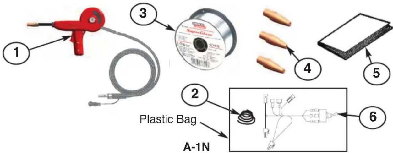
UNPACKING THE SPOOL GUN
The spool gun is factory-assembled and tested, and then packed in its own cushioned carrying case. It is shipped fully-equipped to weld with 0.035 inch diameter aluminum wire. After opening the case, check that it contains the following items:
- One fully assembled K3269-1 spool gun.
- One T11862-65 Conical Compression Spring for use with alloy 5356 wire (spool not included).
- One spool of 0.035 aluminum alloy 4043 wire
- Three S28172-1 contact tips
- One instruction manual (IMT10137)
- One M2182 electrical harness with toggle switch.
INSTALLATION SAFETY PRECAUTIONS
WARNING

ELECTRIC SHOCK CAN KILL.
- Turn the input power OFF at the welding power source before installation or changing drive rolls and/or guides.
- Do not touch electrically live parts.
- When inching with the gun trigger, electrode and drive mechanism are "hot" to work and ground and could remain energized several seconds after the gun trigger is released.
LOCATING SPOOL GUN COMPONENTS AND FEATURES
(See Figure 1.A for Items 1 thru 6)
- Gas Nozzle and Contact Tip.
- Straightened Gun Tube Assembly.
- 1/4-Turn Locking Collar.
- Trigger Assembly.
- Spool Cover: Provides easy, wide-open access to spool and wire drive.
- Locking Knob: Captive in spool cover.
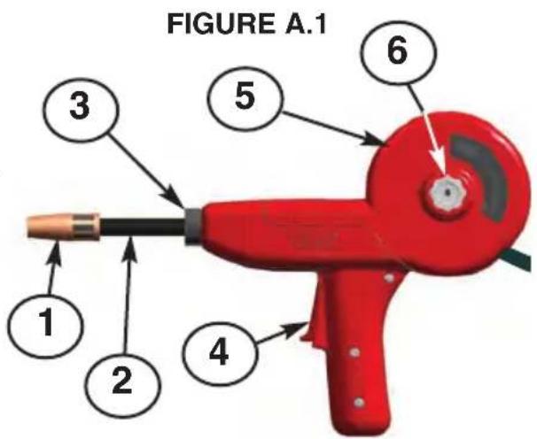
Left Side View
(See Figure A.2 for these following items)
- Integrated Single-Piece Cable: The Magnum® Pro design provides neat and clean appearance; simplifies cable management and reduces entanglements.
- Standard Durable Strain Relief Clamp.
- Three Captive Hex Nuts.
Right Side View
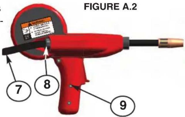
INSTALLATION ASSEMBLY OF ITEMS INSIDE THE MAGNUM® PRO SPOOL GUN FIGURE A.3
- Liner Assembly feeds all specified wire.
- Drive Roll: This Drive Roll feeds all specified wires.
- Idle Roll Assembly: Non-adjustable tension setting for all specified wires
- Incoming Wire Guide: Highly wear-resistant.
- P6 Connector Control Leads: Motor Power and Trigger. (See Maintenance Section for more details)
-
Welding Power and Shielding Gas Machine connection (Sealed with 2 o-rings).
-
Locking Knob: Independently retains the wire spool on the spindle.
- Liner Assembly: Includes a gas seal with the cable connector and is the outgoing wire guide.
- Only 4 sub-assemblies: gun tube; cable; wire drive; trigger.
- Conical spring (not shown) serves as the spool brake (use only with aluminum alloy 5356).
INSTALLATION
SAFETY PRECAUTIONS
WELDING MACHINES
CAUTION
- Read and understand the welding machine's instruction manual and all hazard warnings on equipment and in the manual.
- Wear Nthe Nproper Npersonal Nprotective Nequipment Nfor Nwelding, including but not limited to, safety glasses, hearing protection, welding helmet, welding gloves, and welding leathers.
SPOOL GUN
WARNING

ELECTRIC SHOCK CAN KILL.
- The spool of wire may fall out of the gun if the locking knob is not installed.
-
Metal parts may be at welding voltage (electrically "hot").
-
Metal Nparts Nremain Nat Nwelding Nvoltage Nfor Nseveral Nseconds Nafter Ntriggei released. Read warning label on gun.
- This product shall not be used in precipitation, or in wet or damp locations.
INSTALLATION
| RECOMMENDED WELDING MACHINES | |||
| MACHINE NAME | K-NUMBER | CODE NUMBER | INSTALLATION OF M21182 HARNESS AND SELECTOR SWITCH |
| POWER MIG 216 | K2816-2 | 11817 | NOT REQUIRED |
| POWER MIG 180C | K2473-2 | 11820 | REQUIRED |
| POWER MIG 140C | K2471-2 | 11804 | REQUIRED |
| POWER MIG 180 DUAL | K3018-2 | 11828 | NOT REQUIRED |
| POWER MIG 180C (AU) | K2668-1 | 11444 | REQUIRED |
| POWER MIG 180C (CE) | K2661-1 | 11442 | REQUIRED |
| PRO CORE 125T WELDER | K2479-1 | 11631 | SPOOL GUN USE NOT AVAILABLE |
| PRO MIG 140T WELDER | K2480-1 | 11634 | NOT REQUIRED |
| WELD PAK 125HD WELDER | K2513-1 | 11632 | SPOOL GUN USE NOT AVAILABLE |
| WELD PAK 140HD WELDER | K2514-1 | 11635 | NOT REQUIRED |
| MIG PAK 140 WELDER | K2658-1 | 11636 | NOT REQUIRED |
| EASY CORE 125 WELDER | K2696-1 | 11633 | SPOOL GUN USE NOT AVAILABLE |
| EASY MIG 140 WELDER | K2697-1 | 11637 | NOT REQUIRED |
| CORE PAK 125 WELDER | K2785-1 | 11639 | SPOOL GUN USE NOT AVAILABLE |
| PRO MIG 180T WELDER | K2481-1 | 11646 | REQUIRED |
| WELD PACK 180HD WELDER | K2515-1 | 11647 | REQUIRED |
| MIG PAK 180 WELDER | K2659-1 | 11648 | REQUIRED |
| SP-140T | K2688-2 | 11805 | REQUIRED |
| SP-180T | K2689-2 | 11822 | REQUIRED |
| EASY MIG 180 WELDER | K2698-1 | 11650 | REQUIRED |
INSTALLATION
NOTE: Installation of the M21182 harness and spool gun selector switch is not Nrequired Nfor Nall Nmachines. NIf Na Nspool gun Nswitch Nis pre-installed Nin the machine's wire Ndrive Ncompartment, Nthen Nthe NSPOOL NGUN / NWIRE NDRIVE SLECTOR SWITCH INSTALLATION SECTION can be disregarded.
SPOOL GUN / WIRE DRIVE SELECTOR SWITCH INSTALLATION
- Install the M21182 electrical adapter harness that came with the spool gun per the following instructions.
ELECTRIC SHOCK CAN KILL.
WARNING

- Disconnect Ninput power Nfrom Nthe machine.
OPEN THE MACHINE
- Remove two 5/16" hex hinge screws from door.
- Remove ten 5/16" hex screws from cover.
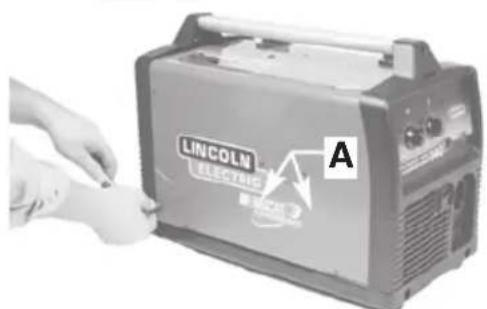
- Remove screws from cover. (A)Nis the location of two 3/4" long screws.
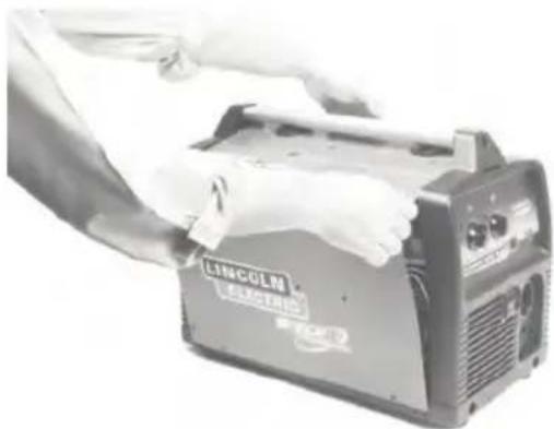
- Remove cover.
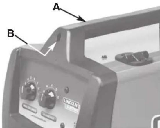
- If machine has a plastic handle (A), then remove screw (B).
INSTALLATION
ELECTRICAL CONNECTIONS
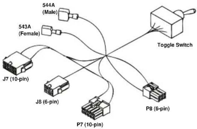
- Adapter harness. All 6 connections shown are used, and each one is unique. (Proceed as follows)
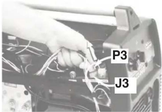
- A. Remove P3 (10-pin)Nfrom board J3 (10-pin).
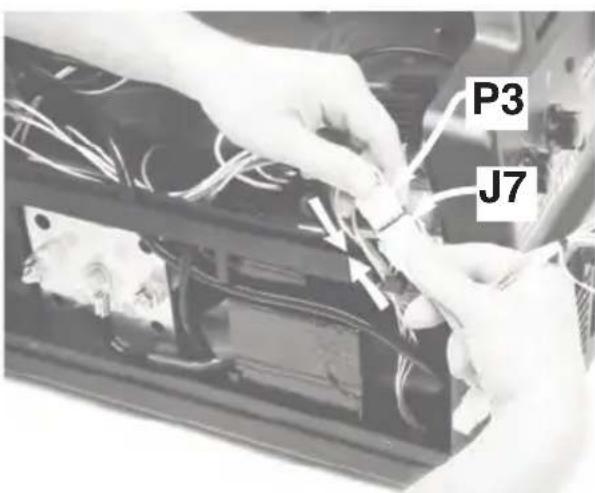
9.B. Connect P3 (10-pin)Nto harness J7 (10-pin).
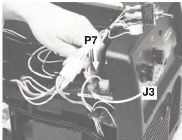
- Connect harness P7 (10-pin)Nto board J3 (10-pin).
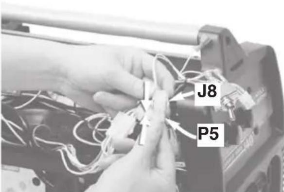
IF MACHINE DOES NOT HAVE OPTIONAL SPOT TIMER. (11.A. thru 11.D.)
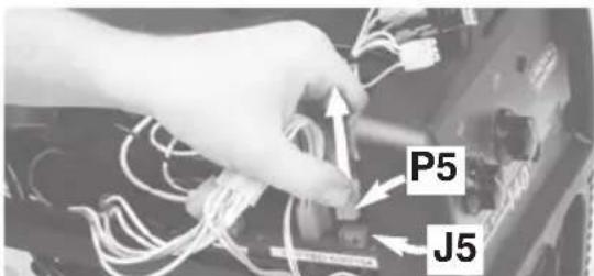
11.A. Remove P5 (6-pin)Nfrom board J5 (6-pin).
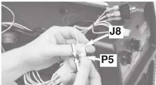
11.B. Connect P5 (6-pin)Nto harness J8 (6-pin).
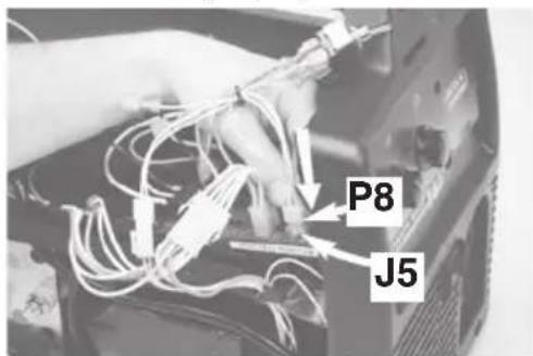
11.C. Connect harness P8 (6-pin) to board J5 (6-pin).
INSTALLATION
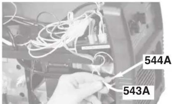
11.D. Find assembled pair of machine terminals (leads 543A & 544A) and disconnect. Go to step 13.
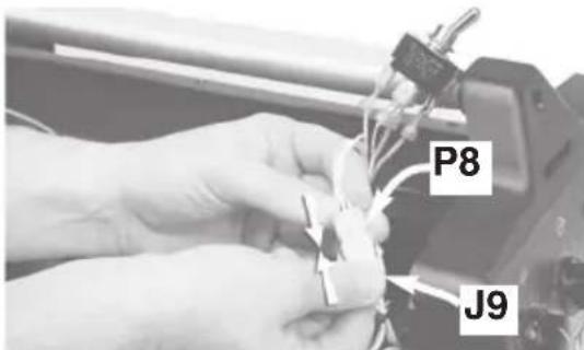
12.C. Connect adapter harness P8 (6-pin)Nto spot timer harness J9 (6-pin).
IF MACHINE DOES HAVE OPTIONAL SPOT TIMER.
(12.A.thru 12.D.)
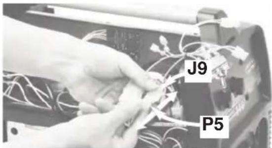
12.A. Remove P5 (6-pin)Nfrom spot timer harness J9 (6-pin).
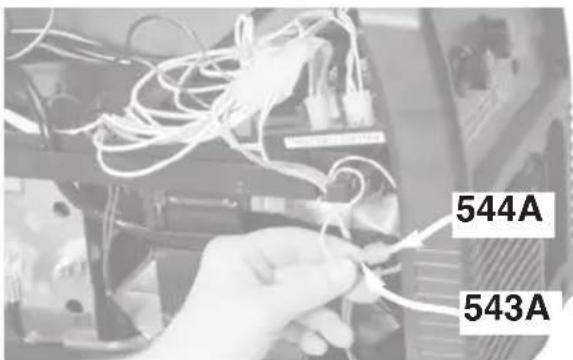
12.D. Find assembled pair of machine terminals (leads 543A & 544A) and disconnect.
12.B. Connect P5N(6-pin) to adapter harness J8 (6-pin).
- Connect terminals:
(A)Nconnect machine male (lead 543A) to adapter harness female (lead 543A).
(B)Nconnect machine female (lead 544A) to adapter harness male (lead 544A).
- Ensure that the locking tabs on all connectors are latched closed.
INSTALLATION
MOUNTING THE SWITCH

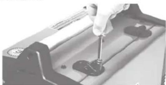
15. Remove the plug button from the panel hole.
16. Plug button is no longer needed. Discard.
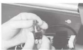
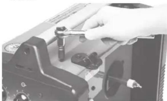
17. Remove mounting nut from switch. Keep mounting nut for installation.
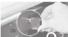
18. Install switch into panel hole, Ensure washer tab is fully seated into smaller hole.
19. Install mounting nut onto switch.
Wrench righthead.
RE-ASSEMBLE MACHINE AS FOLLOWS:
- Reinstall screw into plastic handle (if so equipped).
- Reinstall cover.
-
Reinstall door
-
Reconnect input power to the machine.
INSTALLATION
ROUTINz WzLyING MACHINz PRzPARATION
WARNING

zLzCTRIC SHOCK CAN KILL.
-
yisconnect input power to the machine.
-
Machine polarity setting: Set to DC electrode positive polarity per the machine's Instruction Manual.
- Gas selection and flow rate: Connect 100% welding grade argon gas supply to the machine's gas solenoid valve. Set the supply regulator to deliver a gas flow rate of 20 to 50 SCFH thru the spool gun.]
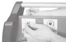
- Flip the machine's wire drive selector switch (behind the access door) to "MAGNUM PRO100SG". (See Figure A.4)
FIGURz A.4
PRzPARING THz SPOOL GUN

WARNING

zLzCTRIC SHOCK CAN KILL.
-
yisconnect input power to the machine.
-
The Conical Spring is used as the spool brake only when feeding the stronger and harder aluminum alloy 5356. The Conical Spring must be removed from the spool gun whenever using the softer aluminum alloy 4043.
INSTALLATION
LOAyING ALUMINUM WIRz
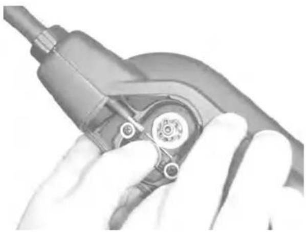
- Remove gas nozzle and contact tip. Remove spool cover by unscrewing captive locking knob.
FIGURz A.5
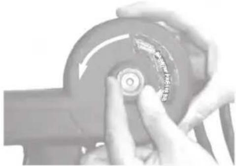
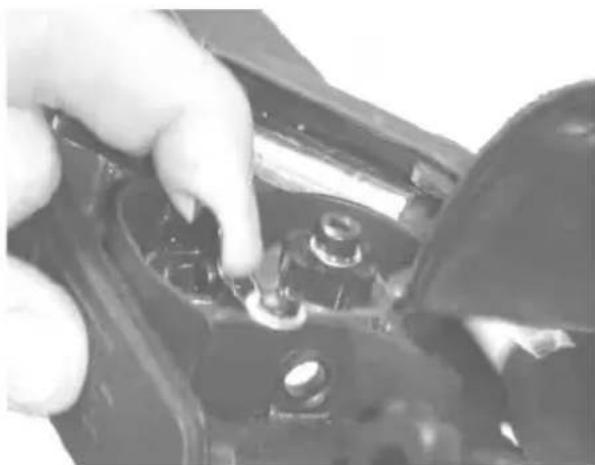
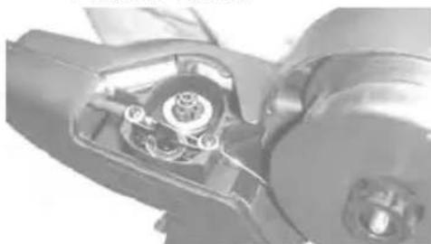
- Remove locking knob from spindle bolt by unscrewing it.
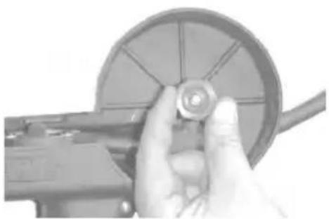
FIGURz A.6
- Select wire alloy and diameter needed. Alloy 4043 and 0.035 wire size shown. Remove packaging and data sheet from wire spool.
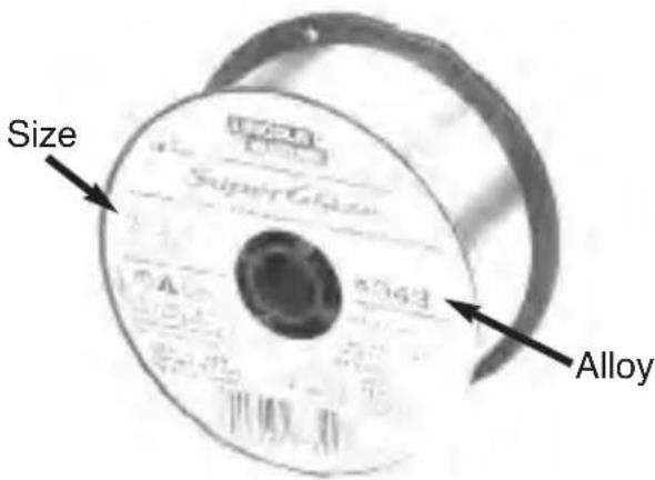
FIGURz A.7
- Extend approximately 12 inches of wire from spool. Straighten it out by back-bending it. Use care to prevent the wire from dereeling.
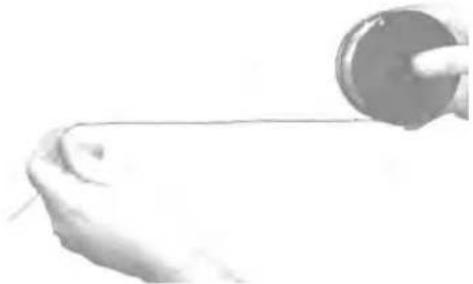
FIGURz A.8
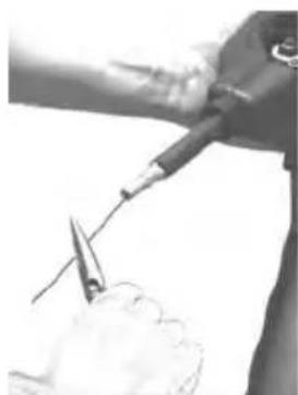
- Cut off bent end of wire, leaving straight section.
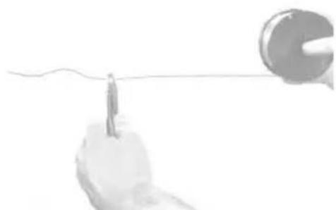
FIGURz A.9
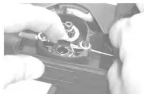
- Gently pull open the idle roll assembly to expose the drive roll groove.
FIGURz A.10
INSTALLATION
- Guide straightened wire through inlet wire guide and toward drive roll groove.
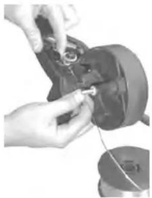
FIGURz A.11
- While holding open the idle roll, slide end of wire through drive roll's groove and toward gun tube liner.
FIGURz A.12
- Slide the wire into the liner until it extends approximately 1 inch beyond the end of the gas diffuser. Release idle roll tab without snapping it.
FIGURz A.13
10a. Alloy 4043: Roll up remaining wire back onto spool and place spool onto gun spindle. Install locking knob and finger-tighten. Go to step 11.
FIGURz A.14
10b. Alloy 5356: Install Conical Spring, small end first, onto gun spindle (A). Roll up remaining wire back onto spool and place spool onto gun spindle. Install locking knob and finger-tighten.
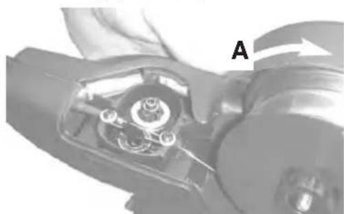
FIGURz A.15
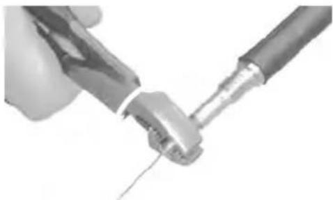
- Grasp the free end of the wire at the gas diffuser and slowly pull approximately 12 to 24 inches of wire through the spool gun. There should only be 1 to 2 lbs. of resistance. If force is greater than 2 lbs. wire is binding in the gun (also see Troubleshooting guide).
FIGURz A.16
INSTALLATION
- Cut off excess wire 1 to 2 inches from gas diffuser. Install properly-sized contact tip slightly past handtight. Install gas nozzle and handtighten.
FIGURz A.17
- Reinstall spool cover. 1: tuck cover's tab in place at arrow and hold with thumb. 2: swing cover closed. 3: finger-tighten locking knob. 4: check for uniform fit all around cover.
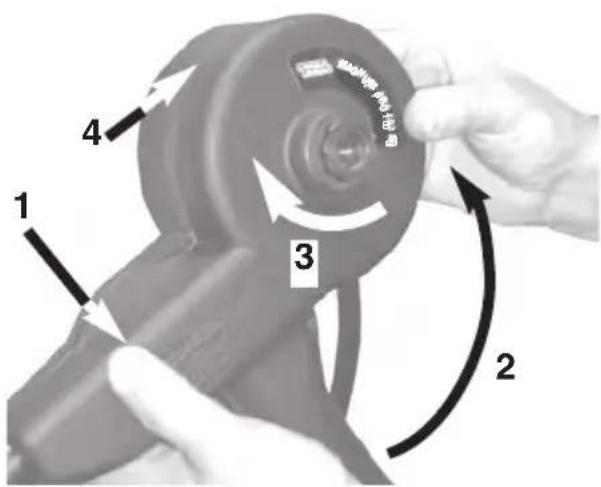
FIGURz A.18
CONNZCTING THz GUN TO THz WzLyING MACHINz
- Disconnect input power to the machine.
- Make sure that the gun locking knob is loosened. (See Figure 20).
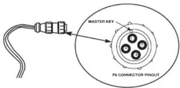
- Fully insert gun cable connection (welding power and gas supply) into machine. Note that the master Key way for P6 connector is located at the arrow.
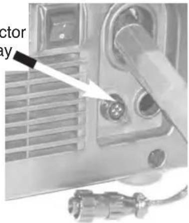
FIGURz A.19
P6 Connector Key way
- Check that the cable connector's end is flush with insulator at A. Tighten gun locking knob (B) onto cable connector.
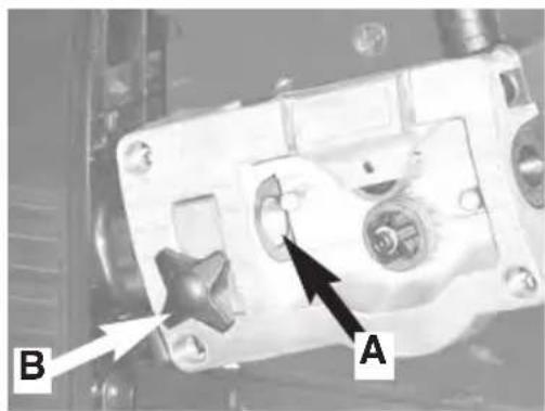
FIGURz A.20
NOTzS
OPERATION
SAFETY PRECAUTIONS
Read and understand this entire section before operating the machine.

WARNING

ELECTRIC SHOCK can kill.
-
Do not touch electrically live parts or electrode with skin or wet clothing.
-
NInsulate yourself from work and ground.
-NAways wear dry insulating gloves. - Read and follow "Electric ShockWarnings" in the Safety section if welding must be performed Nunder Nelectrically Nhazardous Nconditions such as welding in wet areas or on or in the workpiece.

FUMES AND GASES
can be dangerous.
-
Keep your head out of fumes.
-
Use Nventilation Nor Nexhaust Nto Nremove Nfumes from breathing zone.
WELDING SPARKS
can cause fire or explosion
- NKeep flammable material away.
- NDo Nnot Nweld Non Ncontainers Nthat Nhave Ncombustibles.
ARC RAYS
can burn.
- NWear eye, ear and body protection.
Observe Nadditional NSafety NGuidelines detailed in the beginning of this manual.
PRODUCT DESCRIPTION
- Reliable, low-price aluminum welding accessory for novice and experienced welders.
- Completely enclosed system.
- All combinations of specified aluminum alloys and wire diameters can be fed with the same drive roll and liner assembly.
-
Gun cable compactly integrates welding current and gas supplies with gun control functions.
-
Uses reliable gun and feeder hardware from Lincoln's Magnum® 100L Gun, Innershield guns, and small Power Mig products.
MACHINE SPEED AND VOLTAGE TAP SETTINGS
POWER MIG 180T MACHINE
| Alloy: | 4043 | |||
| Wire Size: | 0.030 | 0.035 | ||
| Weldment Thickness | Speed | Voltage Tap | Speed | Voltage Tap |
| 22 ga | 2 | A | 1.5 | A |
| 20 ga | 2.5 | A | 1.5 | A |
| 18 ga | 3.5 | A | 2 | A |
| 16 ga | 3.5 | B | 3 | B |
| 14 ga | 4.5 | D | 3.5 | D |
| 12 ga | 4.5 | E | 3.5 | D |
| 10 ga | 5 | E | 4 | E |
| 3/16 in. | 6.5 | E | 5 | E |
POWER MIG 180T MACHINE
| Alloy: | 5356 | |||
| Wire Size: | 0.030 | 0.035 | ||
| Weldment Thickness | Speed | Voltage Tap | Speed | Voltage Tap |
| 22 ga | 3 | A | 2 | A |
| 20 ga | 3 | A | 2 | A |
| 18 ga | 4 | B | 3 | B |
| 16 ga | 5 | B | 4 | B |
| 14 ga | 5.5 | D | 5 | C |
| 12 ga | 7.5 | E | 6 | E |
| 10 ga | 8 | E | 6.5 | E |
| 3/16 in. | 8 | E | 6.5 | E |
POWER MIG 180C MACHINE
| Alloy: | 4043 | |||
| Wire Size: | 0.030 | 0.035 | ||
| Weldment Thickness | Speed | Voltage Tap | Speed | Voltage Tap |
| 22 ga | 2 | D | 1.5 | D |
| 20 ga | 2 | D | 1.5 | D |
| 18 ga | 3 | E | 3 | E |
| 16 ga | 4 | F | 3.5 | F.5 |
| 14 ga | 4.5 | G | 4 | H |
| 12 ga | 4 | I | 3.5 | J |
| 10 ga | 5 | J | 4 | J |
| 3/16 in. | 5 | MAX | 5 | MAX |
OPERATION
POWER MIG 180C MACHINE
| Alloy: | 5356 | |||
| Wire Size: | 0.030 | 0.035 | ||
| Weldment Thickness | Speed | Voltage Tap | Speed | Voltage Tap |
| 22 ga | 3 | C | 2.5 | C |
| 20 ga | 3.5 | D | 3 | D |
| 18 ga | 5 | E | 3.5 | E |
| 16 ga | 6 | F | 4.5 | F |
| 14 ga | 7 | G | 5.5 | G |
| 12 ga | 8 | H | 6 | H |
| 10 ga | 8 | I | 6 | I |
| 3/16 in. | 9 | MAX | 7 | MAX |
POWER MIG 140C MACHINE
| Alloy: | 4043 | |||
| Wire Size: | 0.030 | 0.035 | ||
| Weldment Thickness | Speed | Voltage Tap | Speed | Voltage Tap |
| 22 ga | 3 | E | 2.5 | E |
| 20 ga | 3 | E | 2.5 | E |
| 18 ga | 5 | F | 4.5 | F |
| 16 ga | 6 | G | 5.5 | G |
| 14 ga | 6.5 | I | 5 | J |
| 12 ga | 7 | MAX | 5.5 | MAX |
| 10 ga | N/A | N/A | N/A | N/A |
| 3/16 in. | N/A | N/A | N/A | N/A |
POWER MIG 140T MACHINE
| Alloy: | 4043 | |||
| Wire Size: | 0.030 | 0.035 | ||
| Weldment Thickness | Speed | Voltage Tap | Speed | Voltage Tap |
| 22 ga | 2 | A | 1.5 | A |
| 20 ga | 2.5 | A | 2 | B |
| 18 ga | 3.5 | B | 2.5 | C |
| 16 ga | 4 | D | 3 | D |
| 14 ga | 4 | E | 3 | E |
| 12 ga | 4.5 | E | 3 | E |
| 10 ga | N/A | N/A | N/A | N/A |
| 3/16 in. | N/A | N/A | N/A | N/A |
POWER MIG 140C MACHINE
| Alloy: | 5356 | |||
| Wire Size: | 0.030 | 0.035 | ||
| Weldment Thickness | Speed | Voltage Tap | Speed | Voltage Tap |
| 22 ga | 2 | E | 1.5 | E |
| 20 ga | 2 | E | 1.5 | E |
| 18 ga | 3 | E.5 | 3 | F |
| 16 ga | 4 | G | 3 | G |
| 14 ga | 3 | I | 3 | J |
| 12 ga | 5 | MAX | 4 | MAX |
| 10 ga | N/A | N/A | N/A | N/A |
| 3/16 in. | N/A | N/A | N/A | N/A |
POWER MIG 140T MACHINE
| Alloy: | 5356 | |||
| Wire Size: | 0.030 | 0.035 | ||
| Weldment Thickness | Speed | Voltage Tap | Speed | Voltage Tap |
| 22 ga | 3 | A | 2.5 | A |
| 20 ga | 3 | A | 2.5 | A |
| 18 ga | 5 | B | 4 | B |
| 16 ga | 5 | D | 4.5 | D |
| 14 ga | 6 | D | 5 | D |
| 12 ga | 6 | E | 5 | E |
| 10 ga | N/A | N/A | N/A | N/A |
| 3/16 in. | N/A | N/A | N/A | N/A |
Weld-Pak 125 MACHINE
| Alloy: | 4043 | |||
| Wire Size: | 0.030 | 0.035 | ||
| Weldment Thickness | Speed | Voltage Tap | Speed | Voltage Tap |
| 22 ga | 2.5 | B | 2 | B |
| 20 ga | 2.5 | B | 2 | B |
| 18 ga | 3 | C | 2 | C |
| 16 ga | 3 | D | 2.5 | D |
| 14 ga | 3.5 | E | 3 | E |
| 12 ga | 3.5 | E | 3.5 | E |
| 10 ga | N/A | N/A | N/A | N/A |
| 3/16 in. | N/A | N/A | N/A | N/A |
OPzRATION
Weld-Pak 125 MACHINE
| Alloy: | 5356 | |||
| Wire Size: | 0.030 | 0.035 | ||
| Weldment Thickness | Speed | Voltage Tap | Speed | Voltage Tap |
| 22 ga | 2.5 | A | 2 | A |
| 20 ga | 2.5 | B | 2 | B |
| 18 ga | 4.5 | C | 4 | C |
| 16 ga | 5 | D | 4.5 | D |
| 14 ga | 6 | E | 5 | E |
| 12 ga | 7 | E | 5.5 | E |
| 10 ga | N/A | N/A | N/A | N/A |
| 3/16 in. | N/A | N/A | N/A | N/A |
After choosing the proper welding wire for your application, load the aluminum wire, connect the gun and cable to the welding machine. (See Installation Section).
WzLDING PROCzDURzS
- Read and understand Arc Welding Safety Precautions located throughout this manual and the Welding Machine's Instruction Manual. Also for helpful hints in welding see (LTW1) the Learn to Weld manual which is supplied with the welding machine.
- Obtain and use the proper personal protective equipment for welding. Connect the WORK (welding ground) cable(-) to piece(s) being welded. Make sure gas hose from cylinder's regulator is connected to welder's gas INLET. Open cylinder's gas valve.
- Connect input power to the machine.
- Turn the machine's power switch to "on". Set wire speed and voltage tap settings to tables which are provided in the beginning of this section.
-
Flip toggle selector switch inside of machine to "MAGNUM® Pro 100SG" position. Press and hold trigger for about 5 seconds to purge hose. Be sure the Gas flow rate is set to 20 to 50 SCFH thru the spool gun.
-
Cut off the aluminum wire so that it extends about 1/4 inches from the contact tip.
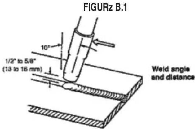
- CTWD (Contact Tip to Work Distance): Position the gun so that the contact tip is nominally 3/8 inches from the joint and tilted with a push angle toward it. The aluminum wire should not contact the workpiece. (See figure B.1)
- Protect the eyes and pull the trigger to begin welding.
- Adjust the hand travel speed of the gun to achieve a proper weld. The emerging wire should stay within the molten puddle and not overrun it. This speed also should not be so slow that either the workpiece excessively melts, or the weld bead becomes excessively large.
- Release the trigger to stop welding.
MAINTznANCz
SAFzTY PRzCAUTIONS
WARNING

zLzCTRIC SHOCK can kill.
-
Only qualified personnel should perform this maintenance.
-
Turn the input power OFF at the disconnect switch or fuse box before working on this equipment.
- Do not touch electrically hot parts.
ROUTINz AND PzRIODIC MAINTznANCz
RzCOMMzNDzD TOOLS
2 Phillips screw-driver
- Slotted screw-driver
- 5/16 inch nut driver
- Torque Wrench
- Adjustable-jaw pliers
- 7/16 inch open-end wrench (gas diffuser)
9/16 inch open-end wrench (gun tube nut)
Welding pliers (optional) - Wire cutter
Wire stripper - Needle nose pliers
- Terminal crimping tool
- Flashlight
- Hand-held electrical meter *
- 3.0 mm metric allen wrench (drive roll screw)
- Tape measure or 6-inch scale
- Tachometer (optional)
*Note: Two meters are used for simultaneously measuring drive motor's voltage and current.
CLZANING AND INSPZCTIONS
Vacuum out any aluminum shavings that may have accumulated inside of the gun. (See Correcting Wire Shaving Issues in this section).
Wipe off dust and debris.
- Check that the gun tube and its lock nut are properly tightened to the cable connector.
- Replace any warning or product identification decals that have become illegible.
P6 CONNZCTOR PIN-OUT TABLz D.1
| Pin No. | Function | Gun Cable Lead Colo |
| 1 | Trigger | White |
| 2 | Trigger | White |
| 3 | + Motor | Red |
| 4 | - Motor | Black |
GAS DIFFUSzR RzPLACzMzNT
This part may need to be replaced if it has accumulated excessive spatter and cannot be cleaned:
- Remove gas nozzle and contact tip.
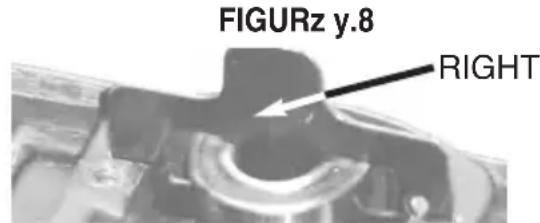
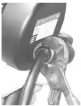
- Carefully grasp gun tube with pliers to prevent accidentally loosening gun tube. Gas diffuser has right-hand threads. Loosen gas diffuser with wrench. (See Figure D.1)
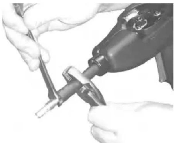
FIGURz D.1
- Install gas diffuser and thread into place in gun tube. Tighten diffuser to 41 to 47 in.-lbs. with Torque Wrench.
MAINTzNANCz
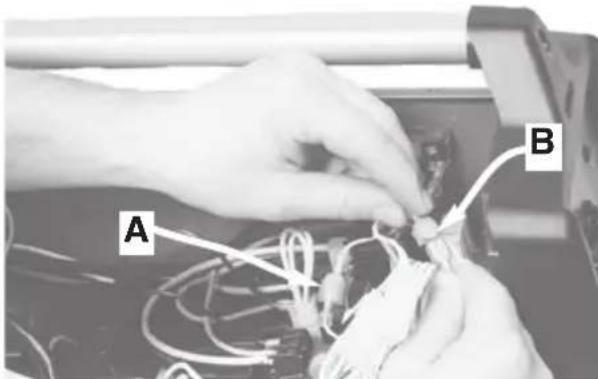
LINzR ASSzMBLY RzPLACzMzNT OR CLzANING
- Replacement liner assemblies are factory-made to the correct length. No cutting is required. The same liner fits all specified wire sizes and alloys:
- Remove gas nozzle, contact tip, and gas diffuser (see Gas Diffuser Replacement in this Section). Remove spool cover.
- Liner removal: Grasp liner with Needle nose pliers at point A. Gently work liner toward cable connector until the liner is loose in it. Be careful not to scrape liner's gas-tight seal (point B) on connector. Withdraw liner out of gun tube (arrow C). (See figure D.2)
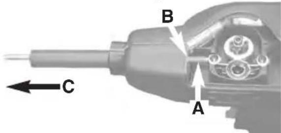
FIGURz y.2
3a. Clean out old liner by blowing out with shop air or obtain a new replacement liner.
4. Slide liner, seal-end first, into gun tube. Grasp liner with pliers at
A. Gently push liner into connector.
B. Check that liner passes through slot in wire feeder.
C. Stop pushing when liner is 1.00 to 1.25 inches from end of gun tube. (See figure D.3)
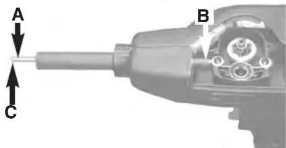
FIGURz y.3
-
Liner installation: See step 4 above.
-
Reinstall gas diffuser (see Figure D.1) and thread into place. Allow the diffuser to push the liner into its final position. Tighten to 41 to 47 in.-lbs. with a torque wrench.
- Reinstall contact tip and gas nozzle.
yRIVz ROLL RzPLACzMzNT
- The same drive roll fits all specified wire sizes and alloys (See Table D.1).
- Replace the drive roll if its feeding groove has become worn or cannot be cleaned of galled aluminum.
- Drive roll removal: Remove wire from the wire drive. Unlock drive roll by rotating twist-lock in either direction. (See figure D.4 and figure D.5).
- Twist-lock is rotated to the locked position, securing drive roll in place.
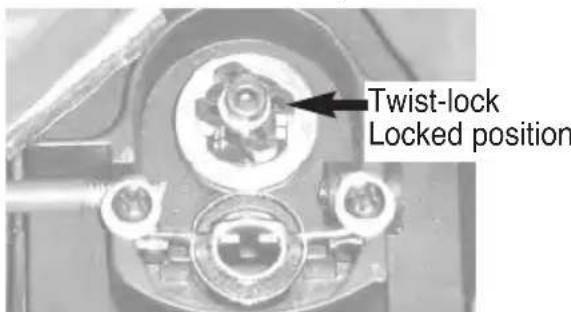
FIGURz y.4
- Twist-lock is rotated to the unlocked position, allowing drive roll removal.
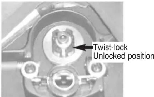
FIGURz y.5
MAINTznANCz
- Drive roll may be removed with pliers, as shown in figure D.6. It may be helpful to relieve the idle roll tension during this step.
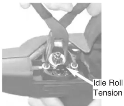
FIGURz y.6
- Clean the drive roll's groove or obtain a new replacement drive roll (if needed).
- Install the drive roll by reversing the above steps 1 thru 7. Either side of the drive roll may be face-up.
IyLz ROLL ASSzMBLY RzPLACzMzNT
- Replace if it is degraded from use; for example, it is becoming galled with aluminum deposits.
- Remove drive roll. (See Maintenance Section)
- Remove both idle roll assembly retaining screws and washers.(See figure D.7)
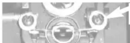
FIGURz y.7
Retaining screws and washers
- Using Needle nose pliers, slowly pull the idle roll assembly out of the wire drive by equally working both sides of the tabbed idle roll spring.
- Insert the new idle roll assembly into the wire drive with the correct orientation, (See figures D.8 and D.9).
Correct orientation. Note that lower spring is not visible in bore of idle roll bearing at arrow.
Incorrect orientation. Note that lower spring is visible in bore of idle roll bearing at arrow.

FIGURz y.9
- Using Needle nose pliers, push the new idle roll assembly into the wire drive until it is fully seated.
- Reinstall the retaining screws and washers. Do not use the screws to draw the idle roll into place. Reinstall the drive roll and wire into the wire drive.
GUN TUBz ASSzMBLY RzPLACzMzNT
- Replace if it is degraded from use; for example, its insulating tube is breaking down.
- Remove liner assembly. (See Maintenance Section)
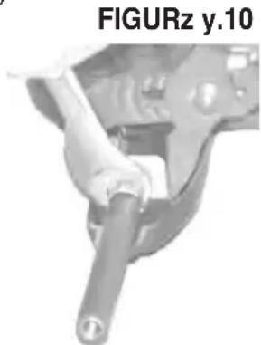
- Remove left side of handle. Loosen gun tube nut with wrench. Nut has right-hand threads. Use adjustable pliers on gun tube mounting plate to prevent cable assembly from rotating in gun handle. (See figure D.10)
MAINTznANCz
- Obtain a new replacement gun tube (if needed). Remove locking nut from old gun tube and install onto new gun tube. Nut should be fully threaded finger-tight against the insulating tube.
- Slide gun tube's external threads through gun tube mounting plate and screw the gun tube by hand into the cable connector until the nut pulls the mounting plate snug against the connector.
- Tighten the nut and mounting plate to the connector with Torque Wrench 10 to 12 ft.-lbs.
- Reassemble gun. Be careful not to pinch any leads between gun handle halves.
WIRz yRIVz ASSzMBLY RzMOVAL ANY INSTALLATION
- There are no serviceable or maintainable parts inside of the wire drive.
- Remove liner assembly (See Maintenance Section figures D.2 and D.3).
- Remove left side of handle.
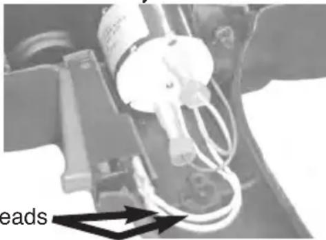
- Disconnect black and red leads from drive motor. Use care to prevent damage to motor's fast-on electrical tabs.
- Slide wire drive out of right handle half.
- When reinstalling wire drive, note the proper motor lead connection in the figure. Reconnect red motor lead to positive (+) terminal, marked with red dot at arrow. Reconnect black lead to other motor terminal. (See figure D.11)
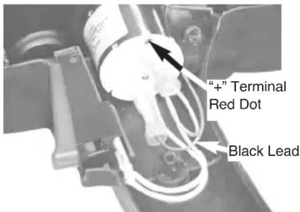
FIGURz y.11
- Reassemble gun. Be careful not to pinch any leads between gun handle halves.
TRIGGzR ASSzMBLY RzPLACzMzNT
- There are no serviceable or maintainable parts inside of the trigger.
- Remove spool cover and left side of handle.
- Slide trigger out of right handle half. Disconnect both white leads from trigger. Use care to prevent damage to electrical leads and the terminals. (See Figure D.12)
FIGURz y.12
- Connect both white leads to the new trigger. Either lead may be connected to either trigger pin (non-polarized connections).
- Slide new trigger into place and reassemble the gun. Be careful not to pinch any leads between gun handle halves.
WzLyING CABlz ASSzMBLY RzPLACzMzNT
-
Generally, there are no serviceable or maintainable parts, except for both o-rings on the machine's power and gas connector; these seals may be replaced. However, there are options:
-
Damage to the four #22 AWG control leads at the gun cable's welding machine end (P6 plug) may be repairable without removing or replacing the entire gun cable. The leads can be spliced and soldered back together, and then reinsulated with heat-shrink tubing. See Table D.1 in Maintenance Section for a description of the connections.
- Otherwise, the damaged gun cable may be replaced.
MAINTznANCz
- Remove liner assembly. (See Maintenance Section)
- Remove gun tube assembly. (See Maintenance Section)
- Remove wire drive assembly. (See Maintenance Section)
- Disconnect trigger. Use adjustable pliers to remove cable strain relief from right handle half. (See figure D.13)
FIGURz y.13
- Pull damaged cable out of the right handle half. The cable connector will fit through the strain relief opening. Mark the new cable at a point 4.750 to 4.813 inches from the end of the cable connector. (See figure D.14)
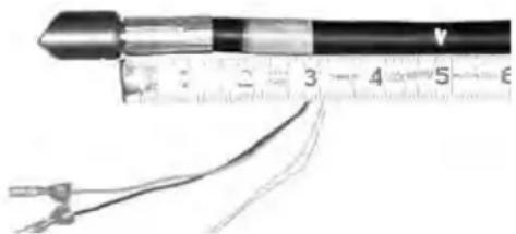
FIGURz y.14
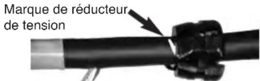
- Place the strain relief onto the new cable at the mark as shown in figure D.15.
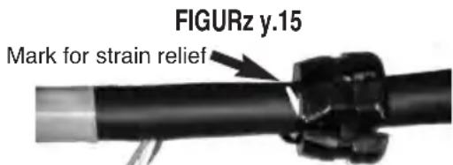
- Install the new gun cable. Pass the cable connector through the opening in the right handle, seat the strain relief in place, and then check to insure the cable is not kinked between strain relief and connector. Reassemble gun by reversing steps 2 through 5.
CORRZCTING WIRz SHAVING ISSUzS
-
If the inlet of the liner assembly is shaving the aluminum wire (the wire is usually peeled off in curled chips) during feeding, the wire feed centerlines of the wire drive and the liner itself may be misaligned.
-
This misalignment may occur whenever the gun tube, wire drive, or welding cable assemblies are replaced.
-
A limited amount of adjustment is available at the gun tube mounting to possibly eliminate the shaving problem.
-
Visually check if wire is centered in the liner's inlet opening. Feed wire through the spool gun and note which side the shaving seems to occur.
- Remove left side of handle. See Figure D.10 Gun Tube Replacement. Slightly loosen gun tube's nut as shown.
- Slide the gun tube in the mounting plate's hole to realign the wire and then retighten the nut as shown. Reassemble the gun.
- Repeat steps 2 thru 4 until shaving is eliminated. A light accumulation of fine dust is also permissible after feeding 1/4 of a spool during welding use.
TABLE D.2
| Consumable parts | Tapered contact tip 0.030(0.8mm) S28172-7 | KP2744-030T | 10-pack |
| Tapered contact tip 0.035(0.9mm) S28172-1 | KP2744-035T | 10-pack | |
| Gas diffuser (S28722) | KP3076-1 | 1-piece | |
| Gas nozzle (S28728-1) | KP3075-1-50F | 1-piece | |
| Periodic replacement parts | Gun tube assembly (S28729-1) | KP3325-1 | 1-piece |
| Drive roll assembly (S26236-2) | KP2529-2 | 1-piece | |
| Liner assembly (S26612) | KP2632-1 | 1-piece |
TROUBLzSHOOTING
HOW TO USE TROUBLESHOOTING GUIDE
WARNING
Service and Repair should only be performed by Lincoln Electric Factory Trained Personnel. Unauthorized repairs performed on this equipment may result in danger to the technician and machine operator and will invalidate your factory warranty. For your safety and to avoid Electrical Shock, please observe all safety notes and precautions detailed throughout this manual.
This Troubleshooting Guide is provided to help you locate and repair possible machine malfunctions. Simply follow the three-step procedure listed below.
Step 1. LOCATE PROBLEM (SYMPTOM).
Look under the column labeled "PROBLEM (SYMPTOMS)". This column describes possible symptoms that the machine may exhibit. Find the listing that best describes the symptom that the machine is exhibiting.
Step 2. POSSIBLE CAUSE.
The second column labeled "POSSIBLE CAUSE" lists the obvious external possibilities that may contribute to the machine symptom.
Step 3. RECOMMENDED COURSE OF ACTION
This column provides a course of action for the Possible Cause, generally it states to contact your local Lincoln Authorized Field Service Facility.
If you do not understand or are unable to perform the Recommended Course of Action safely, contact your local Lincoln Authorized Field Service Facility.
CAUTION
If for any reason you do not understand the test procedures or are unable to perform the tests/repairs safely, contact your Local Lincoln Authorized Field Service Facility for technical troubleshooting assistance before you proceed.
TROUBLzSHOOTING
Observe all Safety Guidelines detailed throughout this manual
| PROBLEMS(SYMPTOMS) | POSSIBLECAUSE | RECOMMENDED COURSE OF ACTION |
| PROBLEMS | ||
| No wire feed occurs when trigger pulled | BarMashine is switched off or unplugged.2. Spool gun is out of wire.3. Contact tip burnback.4. Fully or partially blocked gun tube liner.5. Bird nest.6. Machine(s toggle selector switch is not set to spool gun mode.7. Defective trigger. (contacts open)8. Defective trigger circuit in gun.9. Damaged spool gun motor.10. No motor voltage or current from machine.11. Contact tip size too small for w diameter used. | 1. Switch on or plug in machine.2. Install full spool of specified wire.3. Replace contact tip.4. Remove and clean or replace gun tube liner. (See maintenance section)5. Cut out bird nest, reload wire, and check for proper wire alignment and wire is mechanical resistance.6. Flip switch to proper operating position.7. Replace trigger. (See maintenance section)8. Disconnect gun from machine and check trigger circuit for continuity.9. Contact LASF for possible motor replacement.10. See Troubleshooting section in welding machine(s instruction manual.11. Replace contact tip with one that is the correct size. |
| Sluggish wire feed when trigger is pulled | 1. Drive roll is worn or galled with alu minum.2. Machine(s wire feed speed setting is too low.3. Wire is obstructed somewhere along the wire feed path in the gun.4. Low motor voltage. | 1. Clean drive roll of all aluminum or replace drive roll.2. Increase wire feed speed.3. Check for obstructions: remove ar wire shavings; remove kinked wire; remove and clean or replace gun tube liner (See Maintenance Section ).4. See Troubleshooting section in welding machine(s instruction manual. |
| Drive roll turns in reverse direction. | 1. Motor leads are connected in reverse. | 1. Connect properly. (See maintenance section) |

CAUTION
If for any reason you do not understand the test procedures or are unable to perform the tests/repairs safely, contact your Local Lincoln Authorized Field Service Facility for technical troubleshooting assistance before you proceed.
TROUBLzSHOOTING
Observe all Safety Guidelines detailed throughout this manual
| PROBLEMS(SYMPTOMS) | POSSIBLECAUSE | RECOMMENDED COURSE OF ACTION |
| PROBLEMS | ||
| Intermittent wire feed when trigger is pulled. | 1. Wire is mechanically binding along its feed path inside gun.2. Drive roll has become loose on hub and output shaft.3. Drive roll has become galled with alu-minum.4. Wire has become kinked along its feed path.5. Idle roll assembly is installed backwards.6. Liner assembly is shaving wire. | 1. Check that wire is properly aligned inside gun.2. Check that drive roll is securely fastened in place by SHCS (socket head cap screw); replace hub and twist-lock if worn.3. Remove and then clean or replace drive roll. (See Maintenance Section)4. Manually pull wire slowly thru gun until unkinked wire emerges.5. Install properly. ( See Maintenance Section)6. Check that wire is properly aligned at liner inlet; realign gun tube with wire drive. (See Correcting Wire Shaving Issues Maintenance Section) |
| Frequent occurrence of contact tip burn-back. | 1. Improper welding parameters or technique. (Example: CTWD (Contact Tip to Work Distance) is incorrect.2. Wire may be feeding intermittently. | 1. See Operation Section for proper Welding information.2. See symptoms on intermittent or sluggish wire feed. |
| Poor weld bead appearance (porosity or dull gray oxidized surface). | 1. No gas flow.2. Low gas flow.3. Improper or contaminated shielding gas.4. Welding in a windy environment..5. Improper electrode polarity.6. Improper welding parameters or technique. | 1. See symptom "Low or no gas flow"2. See symptom "Low or no gas flow"3. Check that the gas supplyfls labeling reads 100% argon. Temporarily use alternate, known gas supply and check for appearance improvement.4. Erect a wind shield or move to a non-windy location before welding.5. Reconnect machineis welding output to electrode positive polarity.6. See Operation Section for information. |
CAUTION
If for any reason you do not understand the test procedures or are unable to perform the tests/repairs safely, contact your Local Lincoln Authorized Field Service Facility for technical troubleshooting assistance before you proceed.
TROUBLzSHOOTING
Observe all Safety Guidelines detailed throughout this manual
| PROBLEMS(SYMPTOMS) | POSSIBLECAUSE | RECOMMENDEDCOURSE OF ACTION |
| PROBLEMS | ||
| Low or no shielding gas flow. | 1. Out of gas.2. Gas supply is turned off or disconn- nected.3. Gas supply flow regulator is improperly set.4. Machine's gas solenoid valve has malfunctioned.5. Blockage in gun along gas path.6. Gun cable kinked or flattened.7. Blockage due to excessive spatter accumulation on gas nozzle or gas diffuser.8. Excessive gas leakage fro pply.9. Gas leakage in gun between liner assembly and cable connector.10. Gas leakage at gun-to-feeder connection. | 1. Check that an adequate gas sup- ply is available.2. Check that all gas supp are open.3. Check that gas flow is set between 20 to 50 SCFH.4. See machine's instruction manua5. Gently blow out debris fre tube.6. Attempt to straighten out cable, or replace cable. (See Maintenance Section)7. Clean or replace gas nozzle or gas diffuser.8. Find and repair all leaks.9. Replace liner assembly. (See Maintenance Section)10. Damaged o-rings: replace both seals. Gun connector not fully inserted into machine (See Installation Section). |
| Wire feeder runs or begins feeding wire without pulling the gun trigger. | 1. Defective trigger. (contacts closed)2. Defective (closed) trigger circuit in the welding machine.3. Trigger lead(s) inside gun cable are shorted together or commonly shorted to either welding or motor circuits. | 1. Replace trigger. (See Maintenance Section)2. See machine's instruction manua3. D a m a g e d c o n t r o l l e a d machine's P6 connector and cable; repair if possible. Otherwise, replace gun cable. (See Maintenance Section) for both. |

CAUTION
If for any reason you do not understand the test procedures or are unable to perform the tests/repairs safely, contact your Local Lincoln Authorized Field Service Facility for technical troubleshooting assistance before you proceed.
WIRING yIAGRAM
SPOOL GUN INTERFACE - WIRING DIAGRAM
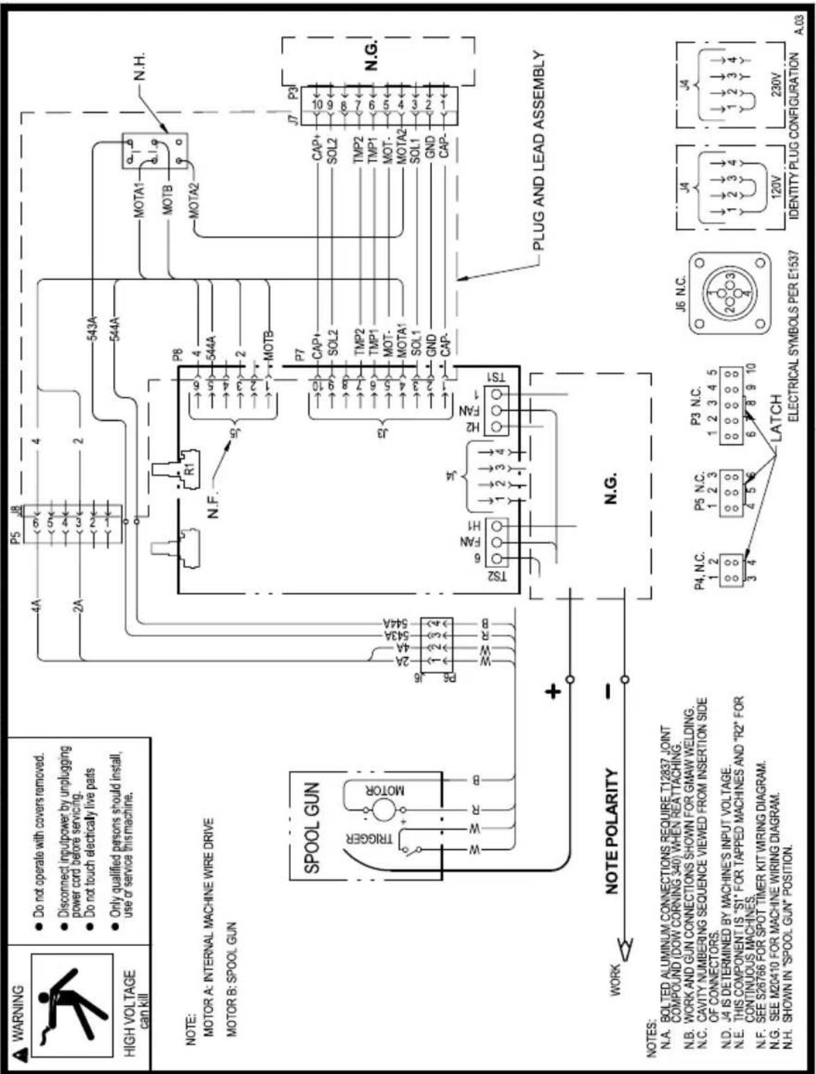
NOTE: This diagram is for reference only. It may not be accurate for all machines covered by this manual. The specific diagram for a particular code is pasted inside the machine on one of the enclosure panels.
M20410-1
NOTES
MANUAu zEUI OPERAZOR
LINCOLN ELECTRIC
Copyright © Lincoln Global Inc.
P a s o 1 . L O C A L Z A C I O N
(SINTOMA).
Paso 2. CAUSA POSIBLE.
Copyright © Lincoln Global Inc.
POLITIQUE D'ASSISTANCE AU CLIENT
FONCTIONNEMENT Section B
- Place the strain relief onto the new cable at the mark as shown in figure D.15.
This parts list is provided as an informative guide only.
It was accurate at the time of printing. These pages are only updated on the Service Navigator DVD and in Lincoln Electric's official Parts Book (BK-34).
When ordering parts, always refer to Lincoln Electric's official Parts Book (BK-34) for the latest pages.
LISTE DE PIECES POUR
Indicates a change this printing
Use only the parts marked "X" the column 1 for Magnum. Use only the parts marked "X" in column 2 for Magnum Pro.
| ITEM | DESCRIPTION | PART NO. | QTY. | 1 | 2 | 3 | 4 | 5 | 6 | 7 | 8 | 9 |
| 1A | Gun Handle (Right Half), Includes: G5666 1 X X | |||||||||||
| 1B | Warning Decal S25815 1 X X | |||||||||||
| 1/4-20 x 2.50 HHS CF000114 1 X X | ||||||||||||
| #6-32 HN | CF000005 | 3 X X | ||||||||||
| Push Nut | S18535-2 | 1 X X | ||||||||||
| 2A | Wire Drive Assembly, Includes: | G5707 | 1 | X | X | |||||||
| Twistlock Drive Roll Assembly | KP2529-2 | 1 | X | X | ||||||||
| Hub | M20860 | 1 X X | ||||||||||
| Twist Lock | S26238 | 1 X X | ||||||||||
| Metric Screw | T14731-72 | 1 X X | ||||||||||
| Loctite 242 or Equivalent (1 drop req'd to lock Screw into place) | NSS | 1 X X | ||||||||||
| Washer | T9695-3 | 1 X X | ||||||||||
| Shaft | NSS | 1 X X | ||||||||||
| Bearing | NSS | 2 X X | ||||||||||
| Gear | NSS | 1 X X | ||||||||||
| Feedplate Base | NSS | 1 | X | X | ||||||||
| Feedplate Cover (Includes Nozzle Insert T12576-6) | G5669 1 X X | |||||||||||
| Nozzle Insert (T12576-6) | NSS | 1 | X | X | ||||||||
| Idle Roll Assembly | S26718 1 X X | |||||||||||
| Motor & Pinion Assembly | NSS | 1 | X | X | ||||||||
| Metric Screw | NSS | 2 | X | X | ||||||||
| Self Tapping Screw | S8025-96 | 2 | X | X | ||||||||
| Plain Washer | S9262-3 | 2 X X | ||||||||||
| 3A | Gun Handle (Left Half) | G5665 1 X X | ||||||||||
| #6-32 x 1.00 SHS | CF000099 | 3 X X | ||||||||||
| 4 | Trigger Assembly | S18932 | 1 | X | X | |||||||
| 5A | Cable Assembly, Includes: | L13018 | 1 | X | X | |||||||
| Male Connector Plug (4 Pin) | S18656 1 X X | |||||||||||
| Cable Clamp | S18658 1 X X | |||||||||||
| 6 | Gun Tube Mounting Plate | S26622 | 1 X X | |||||||||
| 7 | Gun Tube Assembly | KP2631-1 | 1 X X | |||||||||
| 8 | Liner Assembly | KP2632-1 | 1 | X | X | |||||||
| 9A | Spool Cover Assembly, Includes: | S26737 | 1 | X | X | |||||||
| Spool Cover | NSS | 1 | X | X | ||||||||
| Locking Knob | S26711 | 1 X X | ||||||||||
| Product Decal | S26775 1 X X | |||||||||||
| 10 | Grommet | T9274-4 | 1 X X | |||||||||
| 11 | Nut | S19580 | 1 X X | |||||||||
| 12 | Gas Diffuser (Magnum) | KP35-50 | 1 | X | X | |||||||
| 12 | Gas Diffuser (Magnum Pro) | KP3076-1 | 1 | X | X | |||||||
| 13 | Contact Tip (.035 Standard) (Magnum) | KP11-35 | 10 | X | X | |||||||
| Tapered Contact Tip (.035) (0.9mm) (Magnum Pro) | S28172-1 | 10 | X | X | ||||||||
| Contact Tip (.030 Optional) (Magnum) | KP11-30 | 10 | X | X | ||||||||
| Tapered Contact Tip (.030) (0.8mm) (Magnum Pro) | S28172-7 | 10 | X | X | ||||||||
| 14 | Gas Cone Assembly (Magnum) | KP21-50-F | 1 | X | X | |||||||
| 14 | Gas Nozzle (Flush) (Magnum Pro) | KP3075-1-50F | 1 | X | X | |||||||
| 15 | Brake Spring | T11862-65 | 1 | X | X | |||||||
| 16 | Locking Knob | S26711 | 1 | X | X | |||||||
| 17 | Locking Collar | S19701 | 1 | X | X | |||||||
| 18 | Adapter Harness | M21182 | 1 | X | X |
World's Leader in Welding and Cutting Products
Sales and Service through Subsidiaries and Distributors Worldwide
Cleveland, Ohio 44117-1199 U.S.A. TEL: 216.481.8100 FAX: 216.486.1751 WEB SITE: www.lincolnelectric.com