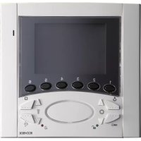
ELVOX 6711 - Monitor Vimar - Free user manual and instructions
Find the device manual for free ELVOX 6711 Vimar in PDF.


| Product type | Hands-free video monitor (video door phone) |
| Brand | Vimar |
| Model | ELVOX 6711 |
| Dimensions (approx.) | 139 x 136 x 59 mm |
| Weight | Approximately 300 g |
| Power supply | 12 V DC via bus (additional power supply art. 6923 possible) |
| Screen | 3.5" color LCD |
| Video standard | PAL |
| Operating temperature | 0°C to +40°C |
| Main functions | Video call, hands-free conversation, door release, self-switching, staircase lighting, intercom call, floor call, ringer off, volume and ringtone settings, contrast, brightness |
| Indicators | Red LED (call excluded, conversation active) and green LED (door open) |
| Connections | BUS line (terminals 1-2), extra bell (+12, CH), floor button (FP, M), extra power (E+, E-) |
| Installation | Surface wall mounting (bracket supplied) or flush mounting (box art. 6149) |
| Material | ABS |
| Compatibility | Due Fili Plus system |
| Compliance | EMC Directive (EN 61000-6-1, EN 61000-6-3), WEEE |
| Included accessories | Mounting bracket for surface mounting |
| Maintenance and cleaning | Clean with a soft, dry cloth. Do not use abrasive products or solvents. |
Frequently Asked Questions - ELVOX 6711 Vimar
User questions about ELVOX 6711 Vimar
0 question about this device. Answer the ones you know or ask your own.
Ask a new question about this device
Download the instructions for your Monitor in PDF format for free! Find your manual ELVOX 6711 - Vimar and take your electronic device back in hand. On this page are published all the documents necessary for the use of your device. ELVOX 6711 by Vimar.
USER MANUAL ELVOX 6711 Vimar
Art. 6611 (6611/F), 661C (661C/F), 6711 (6711/F)
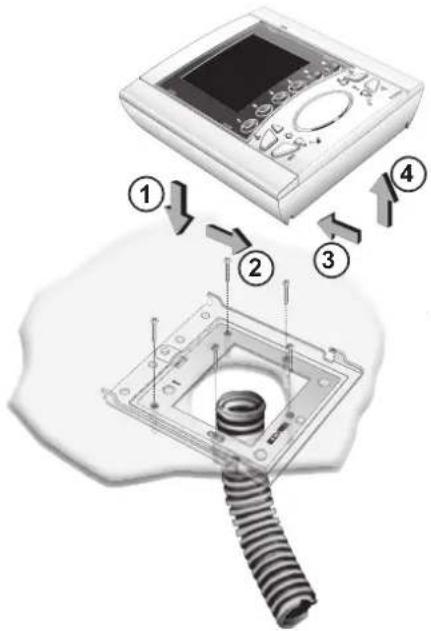
Fig. 2B
INSTALLAZIONE 661C
natural_image
Front view of a medical imaging device with control panel and display screen (no visible text or symbols)Fig. 2C
STABILIZZAZIONE SEGNALE VIDEO
flowchart
graph TD
    A["Mobile Device"] --> B["Digital Display"]
    B --> C["Wireless Cable"]
    C --> D["Radio Station"]
    D --> E["Phone with keypad"]
B
A
A
A
Fig. 3
natural_image
Close-up of a mechanical assembly with a connector and wiring (no visible text or symbols)Art. 6611
natural_image
3D rendering of an electronic device with a central connector and surrounding components (no visible text or symbols)Art. 6711
natural_image
Close-up of a white electronic device with a black connector housing (no visible text or symbols)Art. 661C
PROGRAMMAZIONE
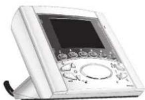
Types 6611, 661C, 6711 are a intercommunicating 6600 series open-voice video interphone with 3,5" colour LCD screen for Due Fili Plus video door entry systems. Type .../F versions have the same features and are programmed and installed in the same way.
"Controls and Adjustments".
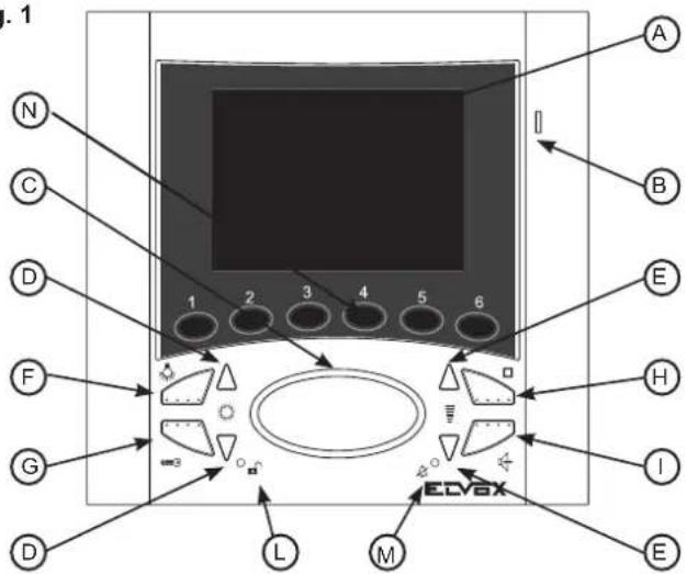
The videointerphones are supplied as standard with 6 push-buttons for auxiliary functions or intercommunicating calls, 8 push-buttons for the following functions: door lock release, self-start of video interphone in the system even when it has not been called, conversation, stair light, internal voice line volume control, ringtone volume control, and two for the ringtone type. Two LEDs (red and green) on the video interphone serve to indicate the following states: call signal mute, unanswered calls, services not available and gate/door open.
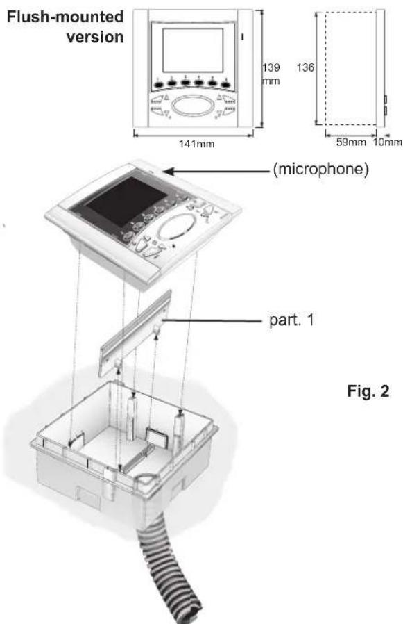
- Flush-mounting of the video interphone (Art. 6611) requires the use of flush-mounted back box type 6149.
- The installation of the surface wall-mounted monitor (type 6711) requires the bracket for the wall-mounting supplied as standard.
Fig. 1
Video interphone technical specifications
- Video interphone in ABS.
- Removable terminal block.
- Flat 3,5" LCD screen.
- Electronic circuit on interchangeable cards.
- PAL standard video signal.
- Operating temperature from 0° to +40°C.
- Electronic ringtone.
- Output for additional ringtone type 860A.
- Supply voltage provided by bus.
- Input for landing calls with different ringtone from entrance panel calls.
- Input for additional power supply (type 6923) if the system is configured to enable simultaneous activation of more than two video interphones.
Controls and adjustments
D) Pair of push-buttons.
1) When the video interphone is ON, the push-buttons can be used to adjust the brightness.
2) When the video interphone is OFF, the push-buttons can be used to select the tune for calls from a speech unit only. To program the tune: hold 1 of the 2 push-buttons down for at least 2 seconds, and press the push-buttons again repeatedly to select the desired tune.
E) Pair of push-buttons
1) In conversation with the "I" push-button pressed, press the "E" push-buttons to increase or decrease the volume of the internal audio.
2) In rest position they adjust the chime volume: keep pressed for at least 2 seconds one of the two "E" push-buttons, press repeatedly the push-buttons to increase or decrease the chime volume. The "E" push-buttons adjust the chime volume even during the immission of the internal or external call sound. Once the sound emission has been ended, they adjust the contrast while the screen is switched on.
F) Push-button : for activating 1st auxiliary service if connected by means of 692RH (e.g. stair lights).
G) Push-button : to open the lock and terminate any conversation in progress.
H) Pushbutton ☐: for self-start. It allows installation selfactivation from the inside without call from the entrance panel.
I) Two-channel conversation push-button: after the call and/or switch-on of the monitor press the pushbutton once to activate the audio. Pressing it once again the conversation terminates.
The red LED remains lit for the whole conversation dwell.
L) Door open LED: the red led is lit when at least one door/gate is open, it turns off when all doors are close (the function is optional according to the type of installation).
M) 'Ringtone mute' LED: if the red LED lights up, this indicates that the call is disabled (see point "E").
The red LED also remains lit for the entire duration of the conversation, i.e. while the audio is active.
N) Push-buttons: for activation of auxiliary services or intercommunicating calls (in function of the programming).
N.B. On the back of the video interphones type 6611, 6711 is a RESET push-button for use during programming, while on video interphone 661C the RESET push-button is on the bottom of the table-top conversion kit and all are equipped with the A-B-C connectors for stabilising the video signal and a colour setting.
Connection and connector terminal board
+12, CH) Additional ringtone connection.
1.2) BUS line.
E+, E-) Additional supply voltage for video-interphone with power supply type 6923.
FP, M) Connection for landing call push-button.
INSTALLATION 6611
- Install the video interphone away from sources of light and heat.
- Flush-mount back box type 6149 in the wall at a height of approximately 1.40 m from the ground to the lower border.
- Remove the plastic cross-piece from the back box (see part. 1, Fig. 2)
- Fix the video interphone to the back box with the 4 screws supplied (Fig. 4).
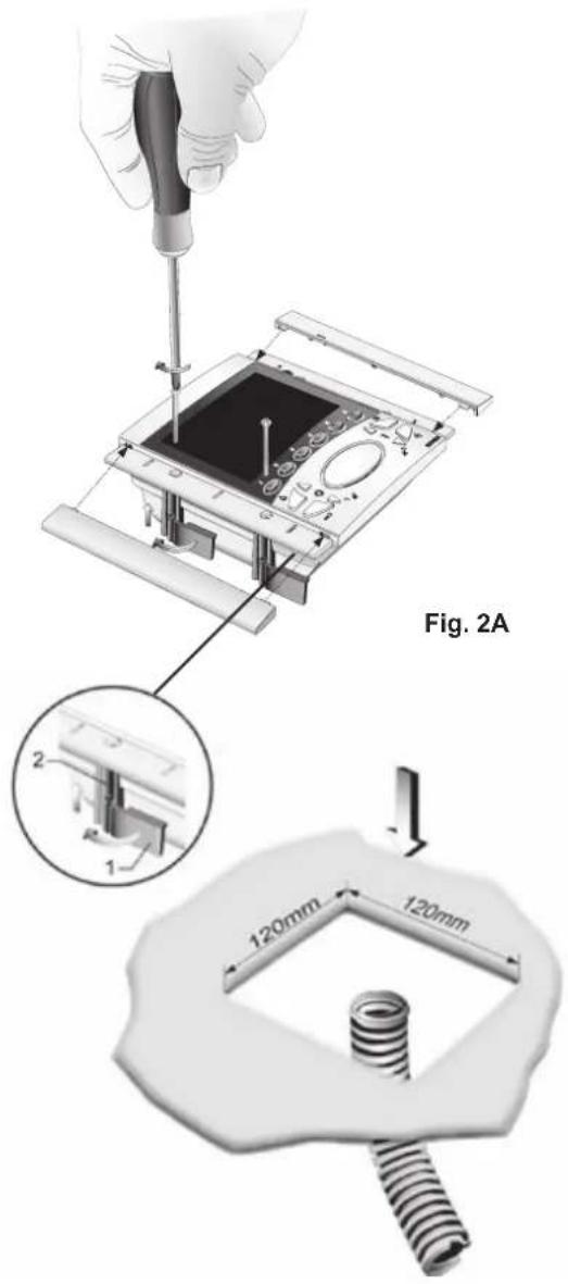
- Fit the side panels, taking care that the panel with the slot for the microphone is fitted on the right (fig. 2).
INSTALLATION OF TYPE 6611 WITH BRACKETS TYPE R660 Install the video interphone away from sources of light and h
- Make a 120x120mm (nearly) hole in the plasterboard wall at 1.40 m high from the floor to the lower border.
- Fix the bracket to the video interphone as indicated in figure, keeping the cursors well aligned to the video interphone sides.
- Carry out the terminal block connections (see wiring diagram).
- Insert the video interphone inside the wall in plasterboard.
- By screwing, the cursors should get aligned orthogonally to the video inter-phone.
- Insert the side grids, paying attention that the one with the slot for the microphone must be inserted on the right.
INSTALLATION OF TYPE 6711
Install the video interphone away from sources of light and heat.
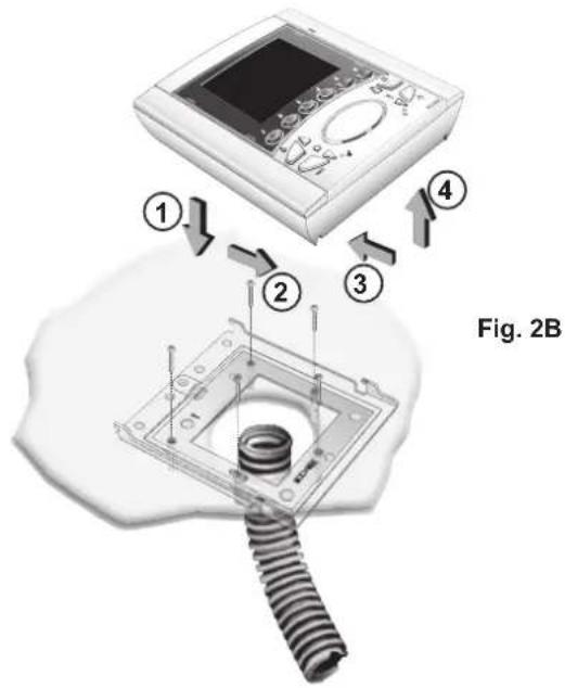
- Fix the monitor fixing plate at 1,40m. from the ground level to the lower border.
- Connect the terminal block. (see wiring diagram)
- Insert the video interphone according to the 1 and 2 arrow direction
- To remove the video interphone from the plate hook, operate with a screw driver on the security lock (placed on the upper side and behind the video interphone), and remove it according to the 3 and 4 arrow direction.
Surface wall-mounting version
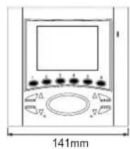
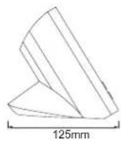
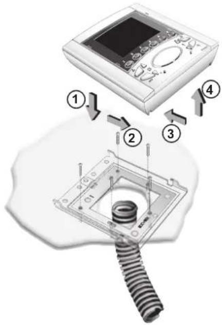
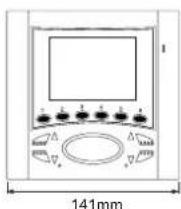
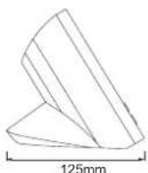
Fig. 2B
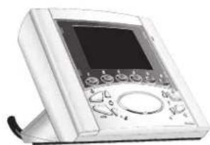
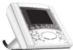
INTSLLATION OF TYPE 661C
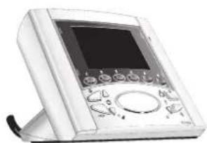
- Fix the monitor support to the wall.
- Connect the terminal block (see wiring diagrams).
- Hook the stud to the support.
Table version
natural_image
Front view of a medical imaging device with control panel and screen (no visible text or symbols)Fig. 2C
VIDEO SIGNAL STABILISATION
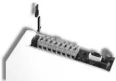
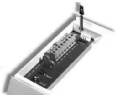
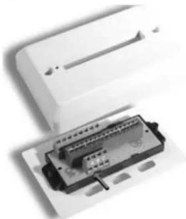
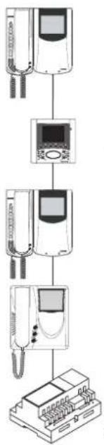
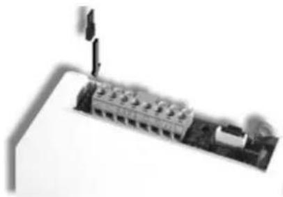
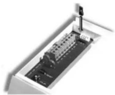
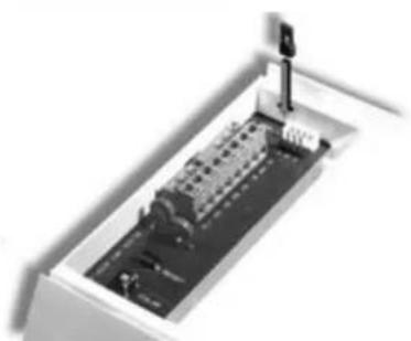
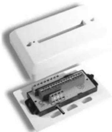
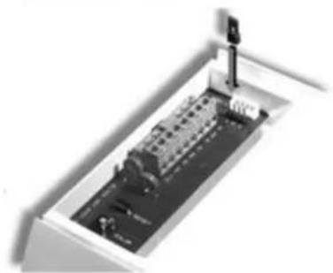
On the rear of monitor type 6611 and 6711 there are some connectors (A-B-C) for the video signal stabilization.
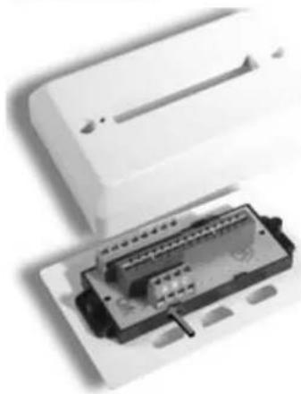
For the table version monitors type 661C the video signal stabilization is carried out by means of a jumper on terminal block A-B-C present on the stud. For types 6611, 6711 and 661C this jumper must be used in installations with several appliances (interphones and monitors) connected in series (Fig. 3).
In series configuration displace the jumper (only in the last set) into "B" position and keep the jumpers of other interphones or monitors in the initial position, i.e. "A" (Fig. 3).
For other wiring configurations see note: "Bus termination" provided below, in the wiring diagrams section.
flowchart
graph TD
    A["Front Panel"] --> B["Analog TV"]
    B --> C["Front-Mounted Device"]
    C --> D["Mobile Phone"]
B
A
A
A
Fig. 3
natural_image
Close-up of a mechanical component with a lever and connector (no visible text or symbols)Art. 6611
natural_image
3D rendering of a mechanical device with ports and a vertical support (no visible text or symbols)Art. 6711
natural_image
Close-up of a white electronic device with an open circuit board (no visible text or symbols)Art. 661C
PROGRAMMING
There are three monitor programming modes: assignment of an identification code or call code (indispensable), assignment of a secondary identification code (for video interphones associated with a master video interphone), programming of push-buttons for auxiliary services and intercommunicating calls (when necessary).
Programming must be performed with the system switched on, without active communication and only after connecting the interphones/video interphones to the system and programming the panels.
Programming the identification code
The identification code is to be programmed by means of an entrance panel (main- "Master"), present on the installation and already configured. The video-interphone is supplied without associated identification code. To check this, press the "G" push-button and the video-interphone will emit a triple "Beep".
Attention: during the interphone/video interphone identification code programming you have 30 seconds from the moment you enter the programming in the interphone/video interphone and the moment you press the call push-button on the panel or you send the code.
Programming phase:
1) Press and hold down "I".
2) Press and hold down also "H" together with "I".
3) Wait for nearly 3 seconds until the red led "M" flashes.
4) Now the microprocessor is physically reset.
5) Release both push-buttons "I" and "H". You have now 5 seconds to carry out any of the described programmings.
6) Press and hold down the "G" lock push-button.
7) After nearly 2 seconds the video-interphone emits a high-pitched tone, it self-starts and gets in communication with the entrance panel.
8) On the entrance panels with push-buttons press the call push-button corresponding to the video-interphone, on the alphanumeric entrance panel, on the contrary, enter the call code and press " 🔊".
9) If on the installation there is already an interphone / video-interphone with the same associated identification code, the panel emits a low-pitched tone and you must repeat the operation from the beginning.
10) If not, the code is associated to the video-interphone and the communication is terminated.
Programming the secondary identification code
The programming of the secondary identification code is required only when you want more than a video- interphone to ring at the same time with the same push-button or call code. The video-interphones which must ring simultaneously are associated with the same push-button to the same group. The "master" interphone / video-interphone is programmed in first place by means of the previous procedure: "programming the identification code". The additional interphones / video-interphones are programmed with the secondary identification code (see table shown in the wiring diagram section enclosed with the electronic TWO WIRE ELVOX entrance panels). A maximum of three audio door entry units plus one group master can be associated with the same group, without the need for programmer Type 950C or SaveProg.
Programming phase:
1) Press and hold down "I".
2) Press and hold down also "H" together with "I".
3) Wait for nearly 3 seconds until the red led "M" flashes.
4) Now the microprocessor is physically reset.
5) Release both push-buttons "I" and "H"
6) Press and hold down the "G" door lock and the "H" self-start push-buttons simultaneously.
7) After 2 seconds the video-interphone emits a high-pitched tone and gets in communication with the entrance panel.
8) Release the door lock "G" and the self-start "G" push-buttons.
9) On the push-buttons entrance panels press the call push-button corresponding to the main (already programmed) interphone / video-interphone, on the alphanumeric entrance panel, on the contrary, enter the same call code of the "Master" interphone / video-interphone and press "☐".
10) If on the installation there is already an interphone / video-interphone with the same associated identification code, the panel emits a low-pitched tone and you must repeat the operation from the beginning.
11) Once the secondary identification code is associated to the video-interphone, the communication is terminated.
To know the number assigned see table shown in the wiring diagram section.
Programming the push-buttons
The video-interphone is supplied with 3 push-buttons for the following functions: lock release, self-start and "stair light" auxiliary service, which activates the 1st relay of the 1st actuator (type 69HR), if connected to the installation and with other 6 push-buttons for intercommunicating calls or auxiliary services. To change the operation type of push-buttons it is necessary to use programmer type 950C or SaveProg, with the exception of the assignation of the functions for the intercommunicating calls and self-start to a specific entrance panel.
Programming the push-buttons for the intercommunicating calls
(With series 8870, Giotto, Petrarca raise the handset of the interphone / video-interphone to call. On the 6600 series keep pressed the talk / listen push-button "l").
Programming phase:
1) Press and hold down "I".
2) Press and hold down also "H" together with "I".
3) Wait for nearly 3 seconds until the red led "M" flashes.
4) Now the microprocessor is physically reset.
5) Release both push-buttons "I" and "H"
6) Press and hold down the "N" push-button to be programmed.
7) After 2 seconds the video-interphone emits a high-pitched tone, while the other interphone / video-interphone emits a three-tone ascending scale.
8) Release the "N" push-button related to the intercommunicating call.
9) On the called interphone / video-interphone (the one with the three-tone scale) press one of the push-buttons programmed as door lock or F1 or F2 or the auxiliary one.
10) A high-pitched tone confirms the end of the procedure.
Repeat the procedure also for the other interphones / video-interphones ad possible intercommunicating call push-buttons.
NOTE: On video door entry units Type 6611, 661C, 6711 with the same procedure it is also possible to program a push-button "N".
Programming the self-start push-button to a specific entrance panel.
Programming phase:
1) Press and hold down "I".
2) Press and hold down also "H" together with "I".
3) Wait for nearly 3 seconds until the red led "M" flashes.
4) Now the microprocessor is physically reset.
5) Release both push-buttons "I" and "H"
6) Press and hold down the "N" push-button to be programmed.
7) After nearly 2 seconds the video-interphone emits a high-pitched tone.
8) Release the push-button "N" related to the self-start.
9) On the entrance panels with push-buttons press the call push-button corresponding to the video -interphone; on the alphanumeric entrance panel, on the contrary, enter the call code and press " 🔊".
10) A high-pitched tone will confirm the end of the procedure.
NOTE: On video door entry units Type 6611, 661C, 6711 with the same procedure it is also possible to program a push-button "N".
Restoring the default values of push-buttons
Programming phase:
1) Press and hold down "I".
2) Press and hold down also "H" together with "I".
3) Wait for nearly 3 seconds until the red led "M" flashes.
4) Now the microprocessor is physically reset.
5) Release both push-buttons "I" and "H"
6) Press and hold down the push-button to be restored to its default setting.
7) After 2 seconds the video-interphone emits a high-pitched tone.
8) Release the push-buttons and press again the push-button to restore to its default setting.
NOTE: On video door entry units Type 6611, 661C, 6711 with the same procedure it is also possible to program a push-button "N".
Deleting all settings
This procedure is recommended when you want to change the ID of a previously programmed video-interphone without retaining its programming parameters.
Programming phase:
1) Press and hold down "I".
2) Then press and hold down also "H" together with "I".
3) Wait for nearly 3 seconds until the red led "M" flashes.
4) Now the microprocessor is physically reset.
5) Release both push-buttons "H" and "I"
6) Press and hold down the self-start push-button "H".
7) After 2 seconds the video-interphone emits a continuous tone for two seconds.
8) Release the self-start push-button "H".
9) During the long tone press the lock push-button "G".
If the deletion procedure was successful, press the lock push-button "G" and the video-interphone will emit a triple "BEEP".
OPERATION
Calls from an entrance panel, intercommunicating calls and landing calls are differentiated by means of different tones.
Landing calls
Calls from entrance panels do not follow the pressing of the call push-button but are generated internally by the video interphone. The call time dwell or cycle consists of a ringtone of 1 second and a pause of 2 seconds, repeated twice (default setting of entrance panel). The duration of "Ding-Dong" and "Ding-Dong-Dang" ringtones does not correspond to the time dictated by the call cycle but to the natural duration of the ringtone. To answer, press and release push-button "I". If push-button "I" has already been pressed during the call, release it and press it again. The call answer time (30 s) and the conversation time (2 minutes by default) are set in the entrance panel parameters. Once the conversation time has elapsed, conversation can be continued if the call is made again within 10 s, from the same entrance panel.
During conversation, the audio can be interrupted momentarily (maximum 5 s) by pressing the "I" push-button. To resume conversation, press the conversation push-button again within 5 s, otherwise communication is lost. Press push-button "I" to terminate the conversation. The red LED "M" remains lit while the audio is active.
Intercommunicating call.
Press the intercommunicating push-button, if programmed, for the interphone/video interphone to be called. The loudspeaker of the calling video interphone will emit a ringing tone (if the call is possible) or an engaged tone (if the call is not possible). On the called interphone/video interphone the ringtone starts sequentially at intervals of 1 s ringing and 4 s pause. The maximum duration of the call is 30 s (6 cycles). If you wish to interrupt the call, press the conversation push-button "I" before an answer is received from the called device. To answer a call, lift the handset on the called interphone/video interphone, or press the conversation push-button. When answered, the video interphone enters direct communication with the called device. Maximum duration of conversation is 5 minutes. When the conversation time has elapsed, the user can continue without replacing the handset if a new call is made within 10 s. Calls from the entrance panel have priority over intercommunicating calls.
Denied calls.
The chime exclusion is indicated by the permanent lighting of the red LED "M". If calls are made from the entrance panel to the video interphone when the call mute is enabled, they are denied. A denied call causes the red LED "M" to briefly switch off according to the number of times calls are denied (maximum 4 denied calls). The signal is repeated every 10 s (approx.). Deletion of denied calls is by re-enabling the ringtone, resetting the video interphone or a system power failure. On the entrance panel, a denied call is indicated by means of a dissuasion tone (a series of "Beeps" at 100ms intervals with a pause of 100ms for a total of 5 s). The message "Do not disturb" also appears on entrance panels with display. The programming of push-buttons "G" and "I" can be changed through two different configurations ("HANDS FREE" or with the speak/listen push-button PRESSED), using the programmer type 950C connected to a push-button entrance panel and/or an alphanumeric entrance panel with software version V4 or bigger. See instructions for programmer type 950C and entrance panels or electronic units.
Lock Button
The lock button of each device works in the following manner.
- Device with handset at rest lock to the last entrance panel with which it has spoken or from which it has been called.
- Device with handset raised but not engaged in a conversation call to switchboard if the Switchboard flag is YES. Otherwise it goes back to the first case.
- Device with handset raised and engaged in an internal conversation as → in the first case.
- Device with handset raised and engaged in an external conversation or called from entrance panel lock to the entrance panel being spoken with or from which it has been called.
In practice a lock is always activated except when the handset is raised and you immediately press the lock button. This can also be taken to the standard case if the system has no porter switchboard and the Switchboard flag is set on NO. NOTE: In series 6600 the equivalent operation is to press for an instant the "open voice" push-button and then the lock release. Also in this case the switchboard is called.
DESCRIPTION
Fig. 2
INSTALLATION DE L'ART. 6611 AVEC LES ÉTRIERS ART. R660
INSTALLATION ART. 661C
natural_image
Front view of a medical or laboratory device with a screen and control panel (no visible text or symbols)Fig. 2C
STABILISATION DU SIGNAL VIDÉO
natural_image
Close-up of a mechanical assembly with a mounted component and a small protrusion (no visible text or symbols)Art. 6611
natural_image
3D rendering of a mechanical device with internal components and a vertical support (no visible text or symbols)Art. 6711
natural_image
Close-up of a white electronic device with an open circuit board (no visible text or symbols)Art. 661C
PROGRAMMATION
Programmation code identification
Abb. 2B
INSTALLATION DES ART. 661C
natural_image
Front view of a medical or laboratory instrument with digital display and control knobs (no visible text or symbols)Abb. 2C
STABILISIERUNG DES VIDEOSIGNALS
natural_image
Close-up of a network switch or connector with a cable, showing ports and wiring (no text or symbols visible)Art. 6611
natural_image
3D rendering of a mechanical device with no visible text or symbolsArt. 6711
natural_image
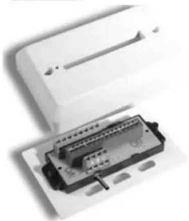
Close-up of a white electronic device with a black connector housing (no visible text or symbols)Art. 661C
PROGRAMMIERUNG
natural_image
Illustration of a handheld electronic device with control panel and buttons, showing four directional arrows (no text or symbols)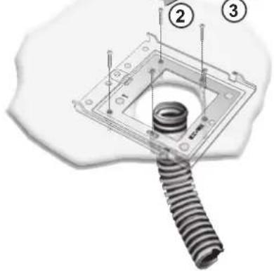
Fig. 2B
natural_image
Front view of a medical imaging device with display screen and control buttons (no visible text or symbols)Fig. 2C
natural_image
Three-panel image showing a device with internal components, no visible text or symbolsArt. 6611
Art. 6711
Art. 661C
PROGRAMACIÓN
IINSTALAÇÃO DO 6711
natural_image
Front view of a medical or laboratory instrument with a digital display and control panel (no visible text or symbols)Fig. 2C
natural_image
Three-panel image showing a device with labeled components, no visible text or symbolsArt. 6611
Art. 6711
Art. 661C
PROGRAMAÇÃO
This note applies to all devices with Due Fili Plus technology equipped with "BUS termination connector or dip-switch", which is identified by the screen-printed letters "ABC" and marked on the wiring diagrams with *
For correct adaptation of the line, make the setting according to the following rule:
Maintain position "A" if the BUS enters and exits from the device;
Move to position "B" (if Elvox cable) or to position "C" (if CAT5 twisted pair cable) if the BUS line terminates in the device itself.
"A" = NO TERMINATION
“B” = TERMINATION 100 ohm
"C" = TERMINATION 50 ohm
INSTALLATIONS WITH PASSIVE DISTRIBUTOR 692D
(DIN rail version)
ALWAYS use output 1 on distributor type 692D (the only one that has no termination jumper).
For termination of type 692D: If outputs "OUT", "2", "3" or "4" are not used, KEEP the jumper on the "TOUT", "T2", "T3" or "T4" connector. The default "TOUT" connector is in the "100" position (Elvox cable), position it to "50" only if using a CAT5 twisted pair cable.
INSTALLATIONS WITH ACTIVE DISTRIBUTOR 692D/2.
The termination jumper must be positioned on "B" (for Elvox cable) or on "C" (for CAT5 twisted pair cable) IF AND ONLY IF the BUS terminates at the device itself. It must be left on "A" if effecting entry-exit using terminals 1-2 on 692D/2.
\*
TERMINACIÓN DEL BUS
“A” = AUCUNE TERMINAISON
"B" = TERMINAISON 100 ohm
"C" = TERMINAISON 50 ohm
INSTALLATIONS AVEC DISTRIBUTEUR PASSIF 692D
(version "rail DIN")
Single and multiple residence video door entry system with one external entrance panel (REF. SI649).
Wiring diagram of additional electronic ringtone type 860A.
The electronic ringtone type 860A features a two or three-note ringtone connected between terminal 7 and terminal 8. The ringtone must be powered at mains voltage.
Wiring diagram for additional mechanical doorbells.
Additional doorbells operating at 12V AC can be connected by using relay type 0170/101 connected as shown in the diagram.
Wiring diagram for door calls
When the door call button is pressed, the video interphone sounds with a different tone from the tone generated by a call from the entrance panel or intercommunicating call.
Wiring diagram for additional power supply type 6923 for powering monitor with simultaneous switch-on.
When using more than two monitors with simultaneous activation an additional power supply type 6923 must be installed for each additional videointerphone. As an alter-native a videointerphones as head-videointerphone must be programmed (by means of programmer type 950C), which will be the only to be turned on at the external call; the other monitors are activated by pressing the self-start push-button or raising the handset. In this case the main monitor switches off automatically.
The instruction manual is downloadable from the site www.vimar.com
Installation rules
Installation should be carried out observing current installation regulations for electrical systems in the Country where the products are installed.
Conformity
EMC directive
Standards EN 61000-6-1 and EN 61000-6-3.

'WEEE - Information for users
If the crossed-out bin symbol appears on the equipment or packaging, this means the product must not be included with other general waste at the end of its working life. The user must take the worn product to a sorted waste center, or return it to the retailer when purchasing a new one. Products for disposal can be consigned free of charge (without any new purchase obligation) to retailers with a sales area of at least 400m^2 , if they measure less than 25cm. An efficient sorted waste collection for the environmentally friendly disposal of the used device, or its subsequent recycling, helps avoid the potential negative effects on the environment and people's health, and encourages the re-use and/or recycling of the construction materials.

- INSTALLAZIONE 661C
- STABILIZZAZIONE SEGNALE VIDEO
- PROGRAMMAZIONE
- "Controls and Adjustments".
- Video interphone technical specifications
- Controls and adjustments
- D) Pair of push-buttons.
- E) Pair of push-buttons
- Connection and connector terminal board
- INSTALLATION 6611
- INSTALLATION OF TYPE 6611 WITH BRACKETS TYPE R660 Install the video interphone away from sources of light and h
- INSTALLATION OF TYPE 6711
- Install the video interphone away from sources of light and heat.
- INTSLLATION OF TYPE 661C
- VIDEO SIGNAL STABILISATION
- PROGRAMMING
- Programming the identification code
- Programming phase:
- Programming the secondary identification code
- Programming the push-buttons
- Programming the push-buttons for the intercommunicating calls
- (With series 8870, Giotto, Petrarca raise the handset of the interphone / video-interphone to call. On the 6600 series keep pressed the talk / listen push-button "l").
- Programming the self-start push-button to a specific entrance panel.
- Restoring the default values of push-buttons
- Deleting all settings
- This procedure is recommended when you want to change the ID of a previously programmed video-interphone without retaining its programming parameters.
- OPERATION
- Landing calls
- Intercommunicating call.
- Denied calls.
- Lock Button
- DESCRIPTION
- INSTALLATION DE L'ART. 6611 AVEC LES ÉTRIERS ART. R660
- INSTALLATION ART. 661C
- STABILISATION DU SIGNAL VIDÉO
- PROGRAMMATION
- Programmation code identification
- INSTALLATION DES ART. 661C
- STABILISIERUNG DES VIDEOSIGNALS
- PROGRAMMIERUNG
- PROGRAMACIÓN
- IINSTALAÇÃO DO 6711
- PROGRAMAÇÃO
- INSTALLATIONS WITH PASSIVE DISTRIBUTOR 692D
- (DIN rail version)
- INSTALLATIONS WITH ACTIVE DISTRIBUTOR 692D/2.
- \*
- TERMINACIÓN DEL BUS
- INSTALLATIONS AVEC DISTRIBUTEUR PASSIF 692D
- (version "rail DIN")
- Wiring diagram of additional electronic ringtone type 860A.
- Wiring diagram for additional mechanical doorbells.
- Wiring diagram for door calls
- Installation rules
- Conformity
- 'WEEE - Information for users
Brand : Vimar
Model : ELVOX 6711
Category : Monitor