
130C - Brush cutter HUSQVARNA - Free user manual and instructions
Find the device manual for free 130C HUSQVARNA in PDF.

| Product type | Brushcutter |
| Brand | Husqvarna |
| Model | 130C |
| Weight (without fuel or cutting attachment) | 5.0 kg |
| Engine | Two-stroke gasoline engine |
| Displacement | 28 cm³ |
| Max. engine power | 0.7 kW at 8000 rpm |
| Idle speed | 2800-3200 rpm |
| Max. recommended speed | 8000 rpm |
| Fuel tank capacity | 0.5 L |
| Fuel mixture | Unleaded gasoline + two-stroke oil (50:1) |
| Spark plug | Champion QCJ-8Y (gap 0.6 mm) |
| Cutting head | Trimmer head (nylon line 2.03-2.67 mm) |
| Approved accessories | Cutting attachment guard (ref. 531 12 79-13), RapidReplace T25/T35 heads |
| Anti-vibration system | Yes, integrated between engine and shaft |
| Safety devices | Stop switch, throttle trigger lock, cutting attachment guard |
| Recommended maintenance | Air filter cleaning, spark plug, cooling system, angle gear lubrication (weekly/monthly) |
| Intended use | Grass cutting only |
Frequently Asked Questions - 130C HUSQVARNA
User questions about 130C HUSQVARNA
0 question about this device. Answer the ones you know or ask your own.
Ask a new question about this device
Download the instructions for your Brush cutter in PDF format for free! Find your manual 130C - HUSQVARNA and take your electronic device back in hand. On this page are published all the documents necessary for the use of your device. 130C by HUSQVARNA.
USER MANUAL 130C HUSQVARNA
natural_image
Silhouette of a selfie stick with a gavel, no text or symbols present130C, 130L
LT13028CCHV, LT13028CSHV
EN Operator's manual 2-23
Transportation and storage....22
Technical data....22
Accessories....23
Introduction
Product description
The product is a grass trimmer with a combustion engine.
Work is constantly in progress to increase your safety and efficiency during operation. Speak to your servicing dealer for more information.
Intended use
The product is used with a trimmer head to cut grass. Do not use the product for other tasks than grass trimming and grass clearing.
Note: National regulations can set limit to the operation of the product.
Only use the product with accessories that are approved by the manufacturer. Refer to Accessories on page 23.
Product overview
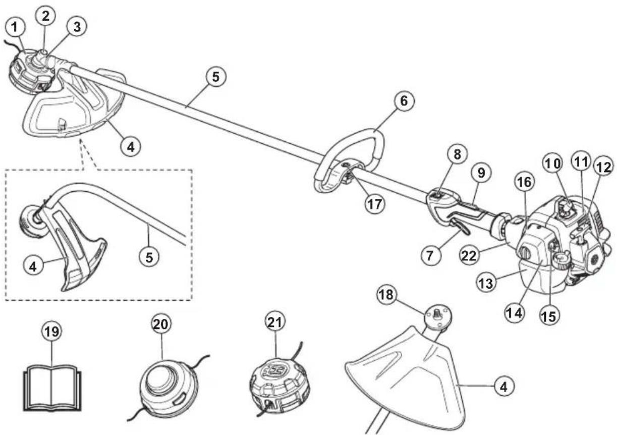
- Trimmer head
- Grease filler cap
- Bevel gear
-
Cutting attachment guard
-
Shaft
- Loop Handle
- Throttle trigger
-
Stop switch
-
Throttle trigger lockout
-
Spark plug cap and spark plug
-
Cylinder cover
-
Starter rope handle
-
Fuel tank
-
Air filter cover
-
Air purge bulb
-
Choke control
-
Handle adjustment
-
Drive disc
-
Operator's manual
-
Trimmer head 130L
-
Trimmer head 130C
-
Vibration damping system
Symbols on the product

WARNING! Be careful and use the product correctly. This product can cause serious injury or death to the operator or others.

Read the operator's manual carefully and make sure that you understand the instructions before you use this product.

Use approved hearing protection. Use approved eye protection.

Make sure that long hair is put above your shoulders.

The product can cause objects to eject, which can cause injury.

Maximum speed of the output shaft.
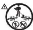
Keep a minimum of 15 m distance to persons and animals during operation of the product.


The arrows show the limit for the handle position.
Air purge bulb.

Choke.

Fuel.
yyyyMMddxxxx The rating plate shows
the serial number. yyyy is the production year, ww is the production week.
Note: Other symbols/decals on the product refer to certification requirements for some markets.
EPA III
![EMISSION CONTROL INFORMATION THIS ENGINE MEETS EXH AND EVP EMISSIONS REGULATIONS FOR [______] SMALL OFF ROAD ENGINES [______] [______] FAMILY/DISP [______] [______] PLT # [______] SKU # [______] EMISSION COMPLIANCE PERIOD [______] SN: [______] REFER TO OWNER'S MANUAL FOR MAINTENANCE SPECIFICATIONS AND ADJUSTMENTS.](/content/2026/04/604544/images/29009b277ad1a4bda2b65d8e68a09bcbdf5dfced50d4829a24555e9cc5067548.jpg)
The Emissions Compliance Period referred to on the Emission Compliance label indicates the number of operating hours for which the engine has been shown to meet Federal emissions requirement. Maintenance, replacement or repair of the emission control devices and system may be performed by any nonroad engine repair establishment or individual.
| EMISSION CONTROL LABEL ABBREVIATIONS | |||||
| General: | |||||
| CAL California | exh/EVP Exhaust and Evapora- | tive | REGS Regulations | ||
| DISPL Displacement EVAP Evaporative SORE | Small off road engines | ||||
| ECS Emission control system | HRS Hours | US EPA United States Environ- | mental Protection Agency | ||
| Exhaust emission control system: | |||
| ECM E | Engine control module (Auto-tune) | OC Ox | dizing Cata-lyst |
| EM Eng | engine modifi-cation | TWC T | three way cata-lyst |
| Evaporative emission control systems: | |||
| C Coextruded(Multilayer) | P Treated HDPEor PE | ||
| N Nylon | S Sealed | ||
California Proposition 65
| WARNING! |
| The engine exhaust from this product contains chemicals known to the State of California to cause cancer, birth defects or other reproductive harm. |
Safety
Safety definitions
Warnings, cautions and notes are used to point out specially important parts of the manual.

WARNING: Used if there is a risk of injury or death for the operator or bystanders if the instructions in the manual are not obeyed.
Product liability
As referred to in the product liability laws, we are not liable for damages that our product causes if:
• the product is incorrectly repaired.
- the product is repaired with parts that are not from the manufacturer or not approved by the manufacturer.
- the product has an accessory that is not from the manufacturer or not approved by the manufacturer.
- the product is not repaired at an approved service center or by an approved authority.

CAUTION: Used if there is a risk of damage to the product, other materials or the adjacent area if the instructions in the manual are not obeyed.
Note: Used to give more information that is necessary in a given situation.
General safety instructions

WARNING: Read the warning instructions that follow before you use the product.
- A clearing saw, brushcutter or trimmer can be dangerous if used carelessly or incorrectly and can cause serious injury or death to the operator or others. It is extremely important that you read and understand the contents of this operator's manual.
- Under no circumstances may the design of the product be modified without the permission of the manufacturer. Never use a product that has been modified in any way from its original specification and always use original accessories. Non-authorized modifications and/or accessories can result in serious personal injury or the death of the operator or others.
- The inside of the muffler contain chemicals that may be carcinogenic. Avoid contact with these elements in the event of a damaged muffler.
- This product produces an electromagnetic field during operation. This field may under some circumstances interfere with active or passive medical implants. To reduce the risk of serious or fatal injury, we recommend persons with medical implants to consult their physician and the medical implant manufacturer before operating this product.
Vibration safety
This product is for occasional operation only. Continuous or regular operation of the product can cause “white finger” or equivalent medical problems from vibrations. Examine the condition of your hands and fingers if you operate the product continuously or regularly. If your hands or fingers have discoloration, have pain, tingle, or are numb, stop work and speak to a physician immediately.
Safety instructions for operation

WARNING: Read the warning instructions that follow before you use the product.
- You must understand the difference between grass clearing and grass trimming before use.
- If you encounter a situation where you are uncertain how to proceed you should ask an expert. Contact your dealer or your service workshop. Avoid all usage which you consider to be beyond your capability.
- Never use a product that is faulty. Carry out the safety checks, maintenance and service instructions described in this manual. Some maintenance and service measures must be carried out by trained and qualified specialists. Refer to Maintenance on page 18.
- All covers, guards and handles must be fitted before you start the product. Ensure that the spark plug cap and ignition lead are undamaged to avoid the risk of electric shock.
- Never use the product if you are fatigued, while under the influence of alcohol or drugs, medication or anything that could affect your vision, alertness, coordination or judgement.
- Do not use the product in bad weather such as dense fog, heavy rain, strong wind, intense cold, etcetera. Working in bad weather is tiring and often brings added risks, such as icy ground, unpredictable felling direction, etcetera.
- The only accessories you can operate with this engine unit are the cutting attachments that we recommend. Refer to Accessories on page 23.
- Never allow children to use or be in the vicinity of the product. As the product is equipped with a spring-loaded start/stop switch and can be started by low speed and force on the starter handle, even small children under some circumstances can produce the force necessary to start the product. This can mean a risk of serious personal injury. Therefore remove the spark plug cap when the product is not under close supervision.
- Running an engine in a confined or badly ventilated area can result in death due to asphyxiation or carbon monoxide poisoning.
- The complete clutch cover and shaft must be fitted before the product is started, otherwise the clutch can come loose and cause personal injury.
- Ensure that no people or animals come closer than 15 m while you work. When several operators are working in the same area the safety distance should be at least 15 m. Otherwise there is a risk of serious personal injury. Stop the product immediately if anyone approaches. Never swing the product around without first checking behind you to make sure that no one is within the safety zone.
- Ensure that people, animals or other things can not affect your control of the product or that they do not come in contact with the cutting attachment or loose objects that are thrown out by the cutting attachment. However, do not use the product unless you are able to call for help in the event of an accident.
- Always inspect the working area. Remove all loose objects such as stones, broken glass, nails, steel wire, string, etcetera, that could be thrown out or become wrapped around the cutting attachment.
- Make sure that you can move and stand safely. Check the area around you for possible obstacles (roots, rocks, branches, ditches, etcetera) in case you have to move suddenly.
Take great care when you work on sloping ground.
natural_image
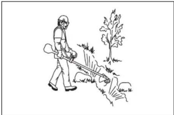
Line drawing of a person spraying water with a tool, next to a tree (no text or symbols)- Keep a good balance and a firm foothold at all times. Do not overreach.
• Always hold the product with both hands. Hold the product on the right side of your body.
- Keep the cutting attachment below waist level.
- Switch off the engine before you move to another area. Fit the transportation guard before you carry or transport the equipment any distance.
- Never put the product down with the engine running unless you have it in clear sight.
- Stop the engine and cutting equipment before you remove material that has wound around the blade shaft. Neither the operator of the product nor anyone else may attempt to remove the cut material while the engine is running or the cutting equipment is rotating, as this can result in serious injury. The bevel gear can get hot during use and may remain so for a while afterwards. You could get burnt if you touch it.
- Watch out for thrown objects. Always wear approved eye protection. Never lean over the cutting attachment guard. Stones, rubbish, etcetera, can be thrown up into the eyes which can cause blindness or serious injury.
- Sometimes branches or grass get caught between the guard and cutting attachment. Always stop the engine before you clean the product.
• Always slow the engine to idle speed after each working operation. Long periods at full throttle without any load on the engine can lead to serious engine damage.
- Listen out for warning signals or shouts when you wear hearing protection. Always remove your hearing protection as soon as the engine stops.
• Overexposure to vibration can lead to circulatory damage or nerve damage in people who have impaired circulation. Contact your doctor if you experience symptoms of overexposure to vibration. These symptoms include numbness, loss of feeling, tingling, pricking, pain, loss of strength, changes in skin color or condition. These symptoms normally appear in the fingers, hands or wrists.
- Do not use a product with a damaged spark plug cap.
- Do not use a product with a defective muffler.
- Keep all parts of your body away from the rotating cutting attachment and hot surfaces.
- Never use a product with a faulty muffler
- Never start or use the product indoors, near combustible material or in spaces that lacks proper ventilation. The exhaust fumes from the engine contain carbon monoxide, an odorless, poisonous and highly dangerous gas. Also, the exhaust fumes are hot and may contain sparks that can start a fire.
Personal protective equipment

WARNING: Read the warning instructions that follow before you use the product.
• Always use approved personal protective equipment when you use the product. Personal protective equipment cannot fully prevent injury but it decreases the degree of injury if an accident does occur. Let your dealer help you select the right equipment.
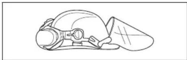
- Use a protective helmet where there is a risk of falling objects.
natural_image
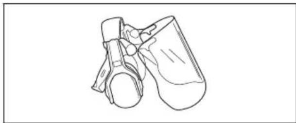
Line drawing of a helmet with a visor and cap (no text or symbols)- Use approved hearing protection that provides adequate noise reduction. Long-term exposure to noise can result in permanent hearing impairment.
natural_image
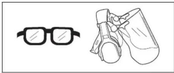
Line drawing of a mechanical device with no visible text or symbols- Use approved eye protection. If you use a visor, you must also use approved protective goggles. Approved protective goggles must comply with the ANSI Z87.1 standard in the USAs or EN 166 in EU countries.
natural_image
Line drawings of eyeglasses and binoculars (no text or symbols)- Use gloves when necessary, for example when you attach, examine or clean the cutting equipment.

- Use protective boots with steel toes and non-slip soles.

natural_image
Line drawing of a pair of boots with visible branding and sole details (no text or symbols)- Use clothing made of a strong fabric. Always use heavy, long pants and long sleeves. Do not use loose clothing that can catch on twigs and branches. Do not wear jewelry, short pants, sandals or go with bare feet. Put your hair up safely above shoulder level.
- Keep first aid equipment close at hand.

Safety devices on the product

WARNING: Read the warning instructions that follow before you use the product.
In this section the product's safety features, its purpose and how checks and maintenance should be carried out to ensure that it operates correctly. See instructions under the heading Introduction on page 2 to find where these parts are located on your product.
The life span of the product can be reduced and the risk of accidents can increase if product maintenance is not carried out correctly and if service and/or repairs are not carried out professionally. If you need further information please contact your nearest servicing dealer.

WARNING: Never use a product with defective safety components. The product's safety equipment must be inspected and maintained as described in this section. If your product fails any of
these checks, contact your service agent to get it repaired.

CAUTION: All servicing and repair work on the machine requires special training. This is especially true of the machine's safety equipment. If your machine fails any of the checks described below you must contact your service agent. When you buy any of our products we guarantee the availability of professional repairs and service. If the retailer who sells your machine is not a servicing dealer, ask him for the address of your nearest service agent.
To do a check of the throttle trigger lockout
The throttle lockout is designed to prevent accidental operation of the throttle control.
- Press the throttle trigger lockout (A) and make sure that the throttle control is released (B). When you release the handle the throttle control and the throttle trigger lockout both move back to their initial positions. This movement is controlled by two independent return springs. This arrangement means that the throttle control is automatically locked at the idle setting.
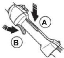
- Make sure that the throttle control is locked at the idle setting when the throttle trigger lockout is released.
natural_image
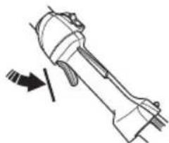
Technical line drawing of a mechanical component with an arrow indicating direction (no text or symbols)- Press the throttle trigger lockout and make sure that it returns to its initial position when you release it.
natural_image
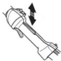
Diagram of a mechanical tool or device with an arrow indicating direction (no text or symbols present)- Do a check of the throttle control and throttle trigger lockout move freely and that the return springs work properly.
natural_image
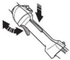
Technical line drawing of a mechanical component with directional arrows indicating motion (no text or symbols)-
Start the product (refer to the instructions under To start a cold engine on page 12) and apply full throttle.
-
Release the throttle and make sure that the cutting attachment stops and remains at a standstill. If the cutting attachment rotates with the throttle in the idle position the carburettor idle setting must be checked. See instructions under the chapter Maintenance on page 18.
To do a check of the stop switch
-
Start the engine.
-
Move the stop switch to the stop position and make sure that the engine stops.
natural_image
Technical line drawing of a mechanical component with an arrow indicating direction (no text or symbols)To do a check of the cutting attachment guard

WARNING: Do not use a cutting attachment without an approved and correctly attached cutting attachment guard. Refer to, Accessories on page 23

WARNING: Always use the recommended cutting attachment guard for the cutting attachment that you use. If
an incorrect or faulty cutting attachment guard is fitted this can cause serious personal injury. Refer to, Technical data on page 22.
The cutting attachment guard prevents injuries from objects that eject in the direction of the operator. It also prevents injuries that occur if you touch the cutting attachment.
natural_image
Illustration of a mechanical clamp or lever assembly (no text or symbols)-
Do a visual check for damages, for example cracks.
-
Replace the cutting attachment guard if it is damaged.
To do a check of the vibration damping system

WARNING: Use of incorrectly wound cord or an incorrect cutting attachment increases the level of vibration.
The vibration damping system decreases vibration between the engine unit and the shaft unit, which makes the operation easier. Refer to Product overview on page 2 to see where the vibration damping units are on your product.
- Stop the engine.
- Do a visual check for deformation and damage, for example cracks.
- Make sure that the vibration damping units are attached correctly.
Cutting attachment

WARNING: Read the warning instructions that follow before you use the product.
- Do the regular maintenance. Let an approved service center regularly examine the cutting attachment to do adjustments or repairs.
• The performance of the cutting attachment increases.
• The life of the cutting attachment increases.
• The risk of accidents decreases. - Only use an approved cutting attachment guard. Refer to Accessories on page 23.
- Do not use a damaged cutting attachment.
Grass trimmer head
- Make sure that you wind the grass trimmer line tightly and equally around the drum to decrease the vibration.
- Use only the approved grass trimmer heads and grass trimmer lines. Refer to To trim the grass on page 14.
- Use a correct length of the grass trimmer line. A long grass trimmer line uses more engine power than a short grass trimmer line.
- Make sure that the cutter on the cutting attachment guard is not damaged.
- Soak the grass trimmer line in water for 2 days before you attach the grass trimmer line to the product. This increases the life of the grass trimmer line.
- Refer to the instructions for the cutting attachment to use the correct procedure to load the cord and the correct cord diameter.
Fuel Safety

WARNING: Read the warning instructions that follow before you use the product.
- Never start the product if you spill fuel on it. Wipe the spillage of and allow remaining fuel to evaporate.
- Never start the product if you spill fuel on yourself or your clothes. Change your clothes and wash any part of your body that has come in contact with fuel. Use soap and water.
- Never start the product if the product is leaking fuel. Check regularly for leaks from the fuel cap and fuel lines.
• Always put the product on a flat surface and make sure the cutting attachment cannot come in contact with any object while you add fuel.
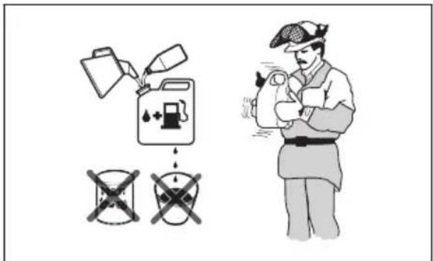
• Take care when handling fuel. Bear in mind the risk off fire, explosion and inhaling fumes. - Observe caution when handling fuel and make sure there is adequate ventilation. Fuel and fuel fumes are highly inflammable and can cause serious injury when inhaled or allowed to come in contact with the skin.
-
Mix and pour fuel outdoors, where there are no sparks or flames.
-
Do not smoke or place hot objects near fuel.
• Always stop the engine and let it cool off for a few minutes before you refuel. - Open the fuel cap slowly so that any excess pressure is released gently when you refuel.
- Tighten the fuel cap carefully after you refueled.
- Clean the area around the fuel cap.
Contamination in the tank can cause operating problems.
• Always move the product 3m (10ft) or further from the refuelling area and source before starting.
Safety instructions for maintenance

WARNING: Read the warning instructions that follow before you use the product.
- Stop the engine, make sure that the cutting attachment stops and let the product cool down before you do the maintenance.
- Disconnect the spark plug cap before you do the maintenance.
- The exhaust fumes from the engine contain carbon monoxide, an odorless, poisonous and very dangerous gas that can cause death. Do not run the product indoors or in closed spaces.
- The exhaust fumes from the engine are hot and can contain sparks. Do not run the product indoors or near flammable material.
- Accessories and changes to the product that are not approved by the manufacturer, can cause serious injury or death. Do not change the product. Always use original accessories.
- If the maintenance is not done correctly and regularly, there is an increased risk of injury and damage to the product.
- Only do the maintenance as this operator's manual recommends. Let an approved Husqvarna service agent do all other servicing.
- Let an approved Husqvarna service agent do servicing on the product regularly.
- Replace damaged, worn or broken parts.
Assembly
Introduction

WARNING: Before you assemble the product, you must read and understand the safety chapter.

WARNING: Remove the spark plug cable from the spark plug before you assemble the product.
To attach the loop handle (130L)
- Attach the loop handle onto the shaft between the arrows.
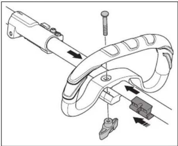
natural_image
Technical diagram of a mechanical assembly with labeled parts, showing motion arrows and no readable text or symbols.-
Move the spacer into the slot of the loop handle.
-
Install the nut, the knob and the bolt. Do not tighten the bolt fully.
-
Adjust the product to a correct position.
-
Tighten the bolt.
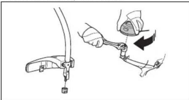
To attach the loop handle (130C)
- Attach the loop handle to the shaft in compliance with the illustration and tighten.
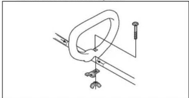
natural_image
Technical line drawing of a mechanical clamp or bracket assembly with mounting base (no text or symbols)- Make sure that the loop handle attaches between the arrows on the shaft.
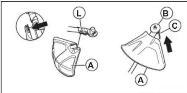
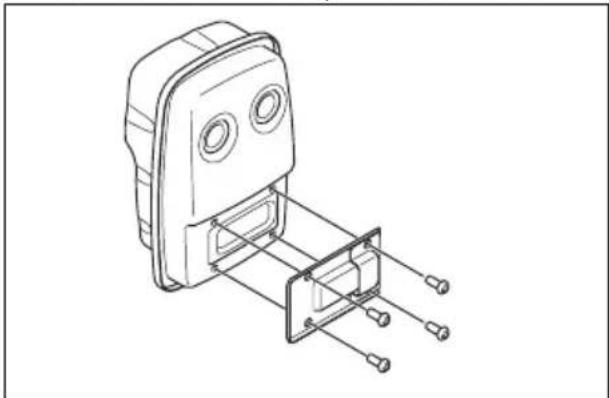
To attach the cutting attachment guard and the trimmer head (straight shaft)
-
Attach the cutting attachment guard (A) to the shaft with the bolt (L).
-
Attach the drive disc (B) to the output shaft.
-
Turn the output shaft until the hole in the drive disc aligns with the hole in the gear housing.
-
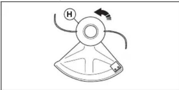
Put a small screwdriver (C) in the hole to lock the shaft.
- Turn the trimmer head (H) counterclockwise to tighten the trimmer head to the gearbox. (Left hand threads.)
natural_image
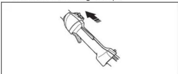
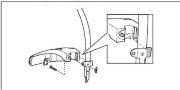
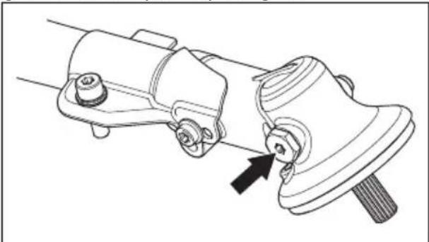
Line drawing of a mechanical device with labeled components and motion arrow (no text or symbols)To attach the cutting attachment guard and trimmer head (curved shaft)
- Attach the guard. Tighten the nut.
natural_image
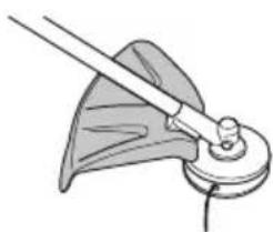
Technical line drawing of a mechanical bracket assembly with an inset detail showing close-up details (no text or symbols)- Attach the dust cup on the shaft.
natural_image
Illustration of a mechanical clamp or bracket assembly with hands adjusting parts (no text or symbols)-
Hold the dust cup with an adjustable wrench to make sure the shaft does not turn.
-
Attach the trimmer head to the shaft. Turn the trimmer head clockwise.
Operation
Fuel
This product has a two-stroke engine.

CAUTION: Incorrect type of fuel can result in engine damage. Use a mixture of gasoline and two-stroke oil.
Premixed fuel
- Use Husqvarna premixed alkylate fuel for best performance and extension of the engine life. This fuel contains less harmful chemicals compared to regular fuel, which decreases harmful exhaust fumes. The quantity of remains after combustion is lower with this fuel, which keeps the components of the engine more clean.
To mix fuel
Gasoline
- Use good quality unleaded gasoline with a maximum of 10% ethanol contents.

CAUTION: Do not use gasoline with an octane grade less than 90 RON/87 AKI. Use of a lower octane grade can cause engine knocking, which causes engine damages.
Two-stroke oil
- For best results and performance use Husqvarna two-stroke oil. - If Husqvarna two-stroke oil is not available, use a two-stroke oil of good quality for air-cooled engines. Speak to your servicing dealer to select the correct oil.

CAUTION: Do not use two-stroke oil for water-cooled outboard engines, also referred to as outboard oil. Do not use oil for four-stroke engines.
To mix gasoline and two-stroke oil
| Gasoline, liter | Two-stroke oil, liter |
| 2% (50:1) | |
| 5 0.10 | |
| 10 0.20 | |
| 15 0.30 | |
| 20 0.40 | |
| US gallon US fl. oz. | |
| 1\ 2\ 12 | |
| 2\ 1/2\ 6\ 12 | |
| 5\ 12\ 78 |

CAUTION: Small errors can influence the ratio of the mixture drastically when you mix small quantities
of fuel. Measure the quantity of oil carefully and make sure that you get the correct mixture.
- Fill half the quantity of gasoline in a clean container for fuel.
- Add the full quantity of oil.
- Shake the fuel mixture.
- Add the remaining quantity of gasoline to the container.
- Carefully shake the fuel mixture.

CAUTION: Do not mix fuel for more than 1 month at a time.
To fill the fuel tank

WARNING: Obey the procedure that follows for your safety.
- Stop the engine and let the engine become cool.
- Clean the area around the fuel tank cap.
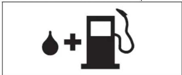
natural_image
Simple black-and-white icon of a fuel pump with a droplet and plus sign (no text or symbols)- Shake the container and make sure that the fuel is fully mixed.
- Remove the fuel tank cap slowly to release the pressure.
- Fill the fuel tank.

CAUTION: Make sure that there is not too much fuel in the fuel tank. The fuel expands when it becomes hot.
- Tighten the fuel tank cap carefully.
-
Clean fuel spillage on and around the product.
-
Move the product 3 m/10 ft or more away from the refueling area and fuel source before you start the engine.
Note: To see where the fuel tank is on your product, refer to Introduction on page 2.
To do before you operate the product

WARNING: Do not use the product without a guard or a guard that is defective.
- Examine the work area to make sure that you know the type of terrain. Examine the slope of the ground and if there are obstacles such as stones, branches and ditches.
- Do an inspection of the product.
- Do the safety inspections, maintenance and service that are given in this manual.
• Make sure that all covers, the cutting attachment guard and the trimmer head are correctly attached and not damaged. Replace damaged parts.
natural_image
Technical line drawing of a mechanical component with no visible text or symbolsTo start a cold engine
- Push the air purge bulb 10 times.
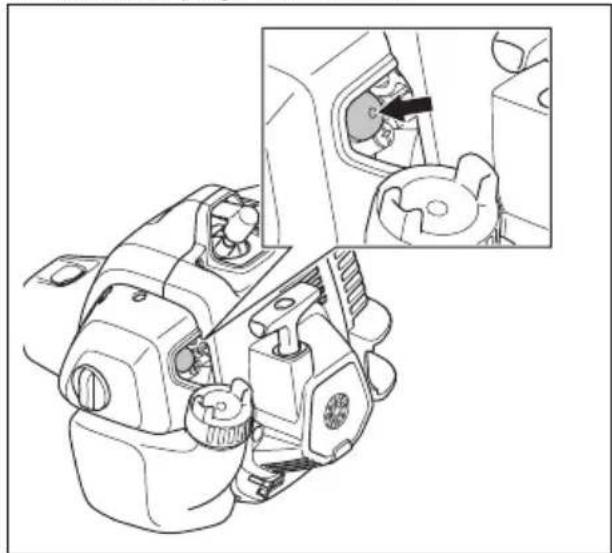
natural_image
Technical line drawing of a mechanical component with an inset showing a close-up view of a gear or valve (no text or symbols present)- Put the choke control in the full choke position.

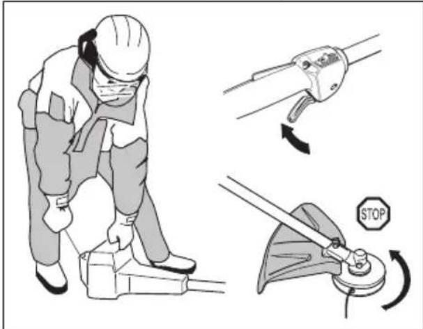
- Hold the product on the ground with your hand. Do not step on the product.
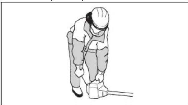
natural_image
Illustration of a worker in safety gear handling equipment (no text or symbols)
WARNING: Do not pull the throttle trigger while you start the engine.
- Pull the starter rope handle 3 times with force.

CAUTION: Do not pull the starter rope until it stops. Do not let go of the starter rope when it is fully extended. Release the starter rope slowly. Failure to obey these instructions can cause damage to the engine.
- Push the choke control down to the half choke position in the center.
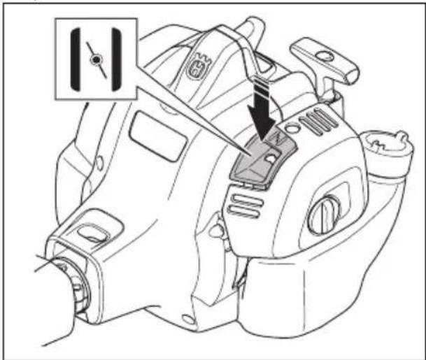
natural_image
Technical line drawing of a sewing machine component with a close-up inset showing a fastener (no text or symbols present)- Pull the starter rope handle until the engine starts.
Note: If the engine does not start, do the start procedure from step 1.
- Let the engine run for 10 seconds.
- Push the choke control fully down to the no choke position.
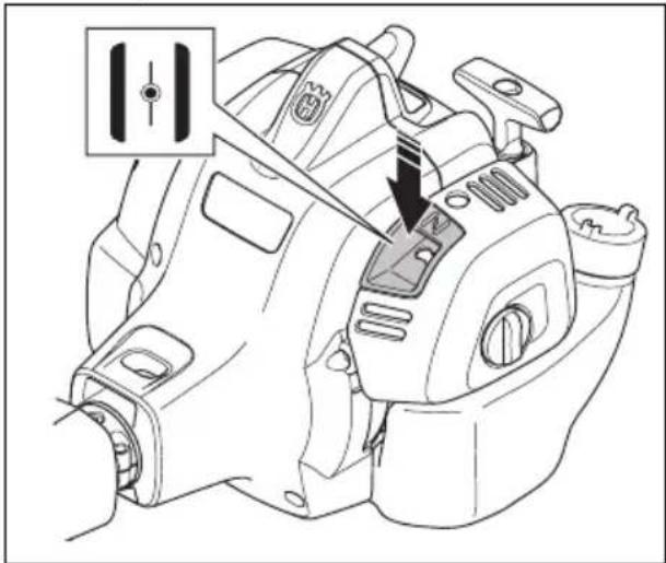
natural_image
Technical line drawing of a mechanical assembly with a tool inserted, showing no text or symbols.To start a warm engine
- Move the choke lever to the FULL CHOKE position.
- Move the choke lever to the HALF CHOKE position.
- Pull the starter rope handle quickly until the engine runs.
- Move the choke lever to the NO CHOKE position.
About the surface

WARNING: Do not put parts of your body in the grey marked area. If you touch the grey marked area it can result in burns to the skin. It can also cause
electrical shock if the spark plug cap has been damaged. Do not use a product with a damaged spark plug cap.
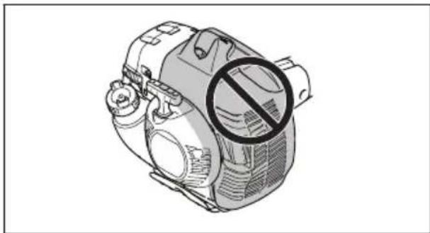
natural_image
Technical illustration of a mechanical device with a circular symbol indicating no prohibition (no text or labels present)To start the engine when the fuel is too hot
If the product does not start, the fuel can be too hot.
Note: Always use new fuel and decrease the operation time during warm weather.
- Put the product in a cool area away from open sunlight.
- Let the product cool down for 20 minutes at minimum.
- Press the air purge bulb again and again for 10-15 seconds.
- Obey the procedure to start a cold engine. Refer to To start a cold engine on page 12.
To stop the product
- Push the stop switch to stop the engine.
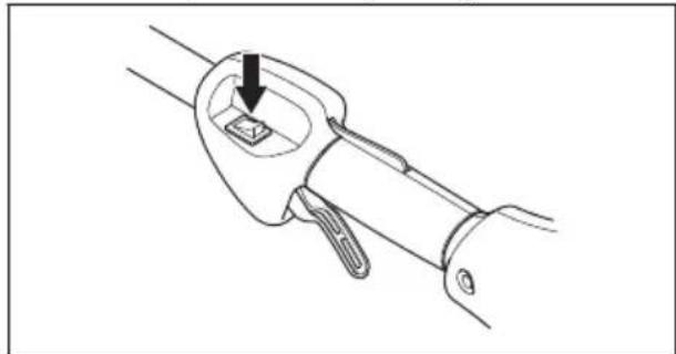
natural_image
Line drawing of a mechanical tool or connector with a black arrow pointing to a component (no text or symbols present)Note: The stop switch automatically goes back to its initial position.
Grass trimming with a trimmer head
To trim the grass
- Hold the trimmer head immediately above the ground at an angle. Do not push the trimmer line into the grass.
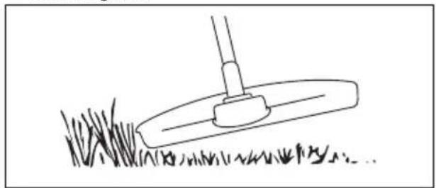
natural_image
Simple line drawing of a grassy slope with a small utility pole (no text or symbols)- Decrease the length of the trimmer line by 10-12 cm / 4-4.75 in.
- Decrease the engine speed to decrease the risk of damage to plants.
- Use 80 % throttle when you cut grass near objects.
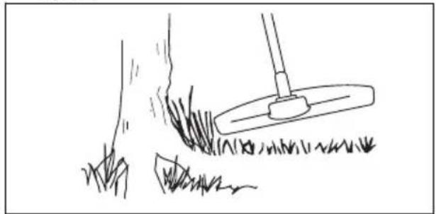
natural_image
Simple line drawing of a grassy field with a small plow and a tool, no text or symbols present.To cut the grass
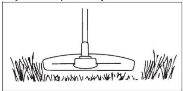
- Make sure that the trimmer line is parallel to the ground when you cut the grass.
natural_image
Simple line drawing of a grassy field with a small mechanical component at the top (no text or symbols)-
Do not push the trimmer head to the ground. This can cause damage to the product.
-
Move the product from side to side when you cut grass. Use full speed.
natural_image
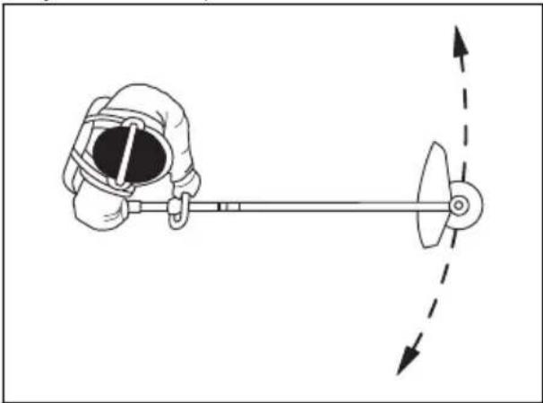
Illustration of a person using a tool to interact with a mechanical device, showing motion direction (no text or symbols)To sweep the grass
The airflow from the rotating trimmer line can be used to remove cut grass from an area.
- Hold the trimmer head and the trimmer line parallel to the ground and above the ground.
- Apply full throttle.
- Move the trimmer head from side to side and sweep the grass.

WARNING: Clean the trimmer head cover each time you assemble new trimmer line to prevent unbalance and vibrations in the handles. Also do a check of the other parts of the trimmer head and clean it if necessary.
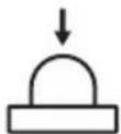
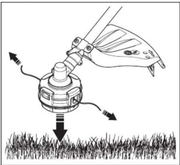
To extend the trimmer line
- When the trimmer line becomes short during operation, tap the trimmer head on a hard, flat surface to extend more trimmer line. You must operate the product at full speed to get the best result.
natural_image
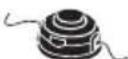
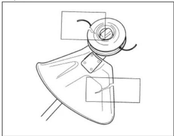
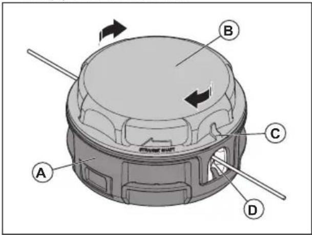
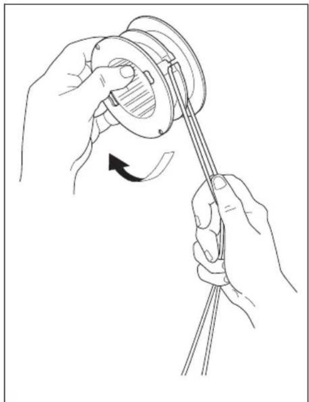
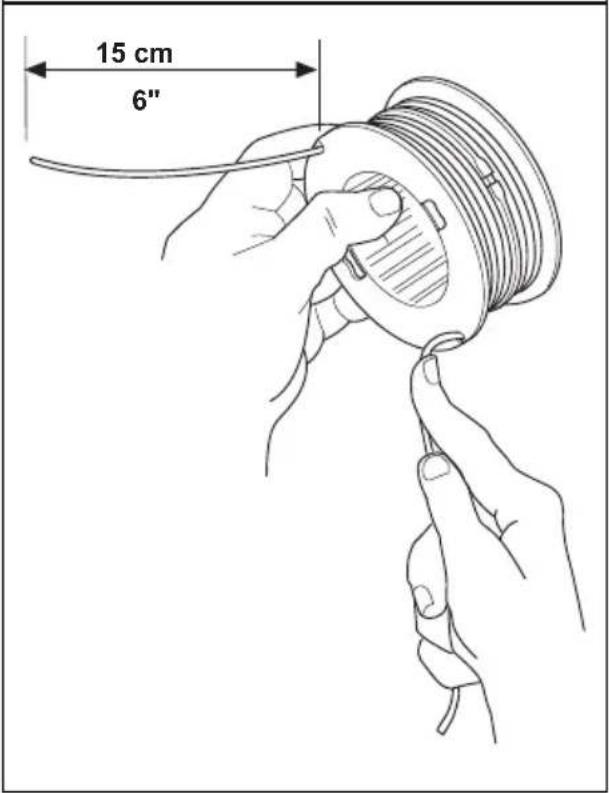
Diagram of a butterfly wing spraying water onto grass, with arrows indicating direction (no text or symbols)To replace the trimmer line 130C
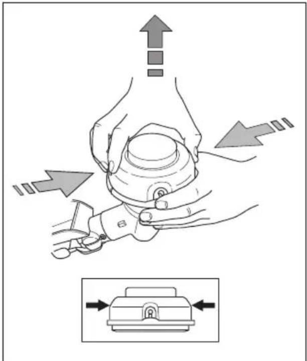

natural_image
Technical line drawing of a mechanical assembly showing top, front, and side views of a component (no text or symbols)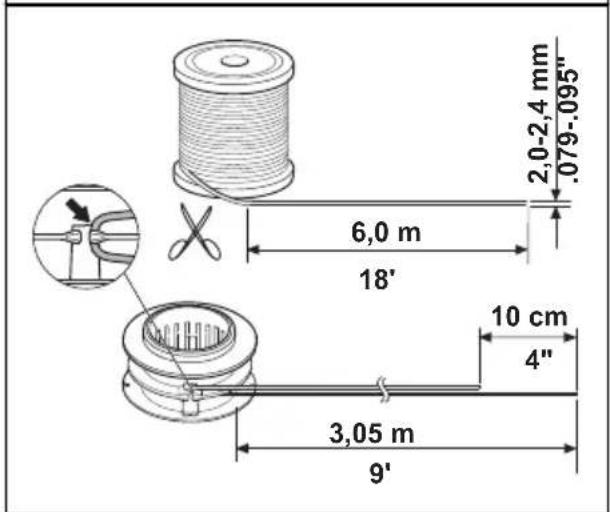
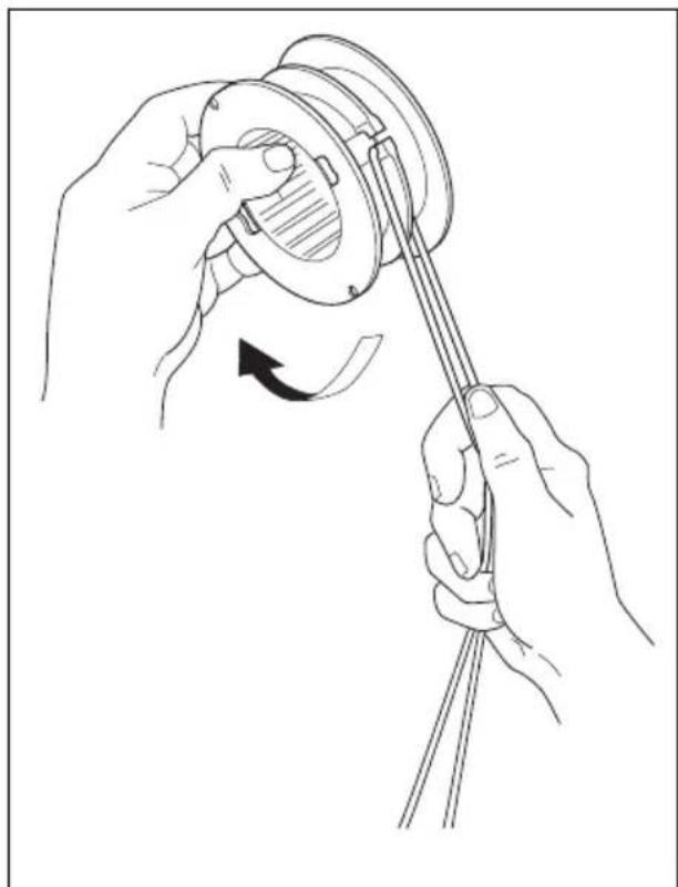
natural_image
Line drawing of hands holding a mechanical component with a rotating arrow indicating rotation (no text or symbols)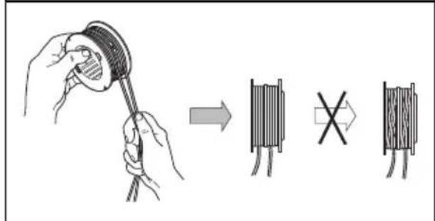
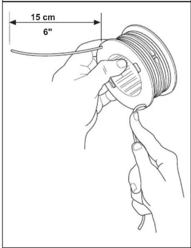

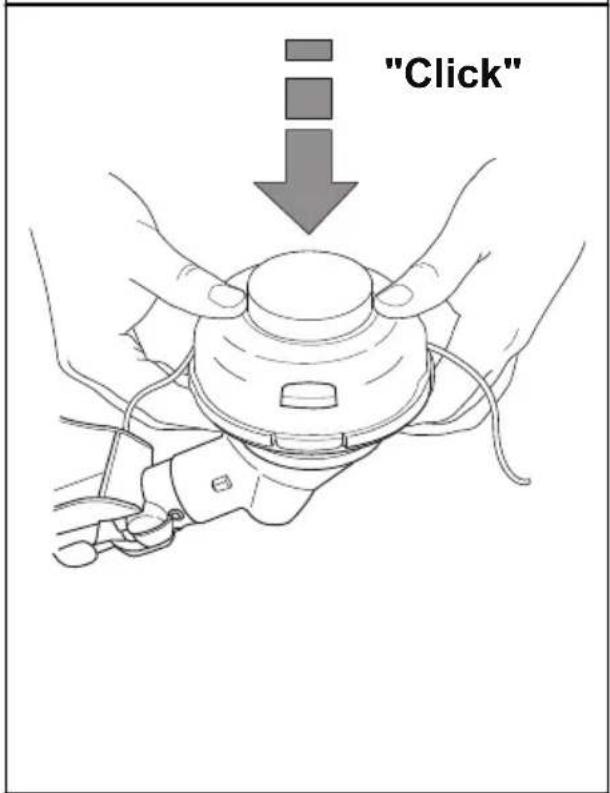
natural_image
Line drawing showing hands assembling a mechanical component with a downward arrow indicating assembly (no text or symbols)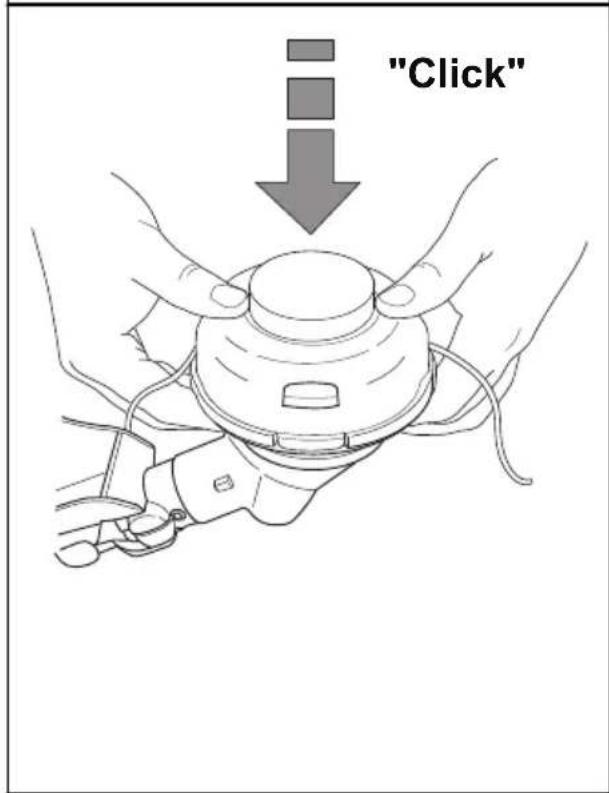
To replace the trimmer line (130L)
- Hold the lower half (A) of the trimmer head with one hand. Use your opposite hand to turn the top half (B) of the trimmer head.
a) For straight shaft grass trimmers, turn the top half of the trimmer head clockwise.
b) For curved shaft grass trimmers, turn the top half of the trimmer head counterclockwise.
Note: It is not necessary to push the top half of the trimmer head down when you turn it.
Note: When you turn the top half of the trimmer head, you will hear a click.
- Continue to turn the top half of the trimmer head until the triangle (C) aligns with the hole (D).
- Remove and discard the remaining trimmer line.
- Cut approximately 6.7 m/22 ft of new trimmer line.
- Put 1 end of the trimmer line into 1 of the holes.
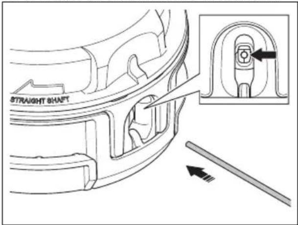
- Push the trimmer line through the trimmer head and through the opposite hole.
natural_image
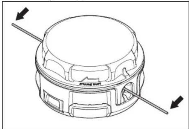
Technical line drawing of a mechanical component with directional arrows indicating force or movement (no text or symbols)- Pull the trimmer line through the trimmer head until there is an equal length of trimmer line on each side.
- Hold the lower half of the trimmer head stable with one hand. Use your opposite hand to turn the top half of the trimmer head. Continue to turn the top half of the trimmer head until approximately 127 mm/5 in of the trimmer line is extended from each hole.
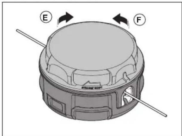
a) For straight shaft grass trimmers, turn the top half (E) of the trimmer head clockwise.
b) For curved shaft grass trimmers, turn the top half (F) of the trimmer head counterclockwise.
Note: If the trimmer line is too long on one side of the trimmer head, cut the trimmer line to the correct length.
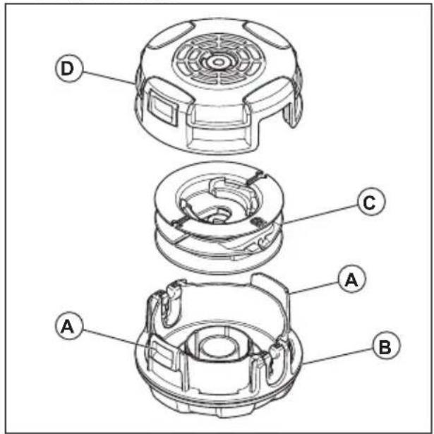
To examine and clean the trimmer head 130L
- Push the tabs (A) to remove the lower half (B) of the trimmer head.
-
Remove the spool (C).
-
Remove and discard any pieces of trimmer line and any unwanted material from the trimmer head and spool.
-
Put the spool in the lower half.
-
Attach the top half (D). Make sure that all parts are in the correct position and are correctly aligned.
-
Turn the assembled trimmer head with your hand. Make sure that the top and bottom halves are fully closed and the tabs are fully engaged.
-
To replace the trimmer line see To replace the trimmer line (130L) on page 17.
Maintenance
To adjust the idle speed
Your Husqvarna product is made to specifications that decrease harmful emissions.
- Make sure that the air filter is clean and that the air filter cover is attached to the product.
- Turn the idle speed screw (T) clockwise until the cutting attachment starts to turn.
natural_image
Technical line drawing of a mechanical assembly with a tool and directional arrow (no text or symbols)- Turn the idle speed screw (T) counterclockwise until the cutting attachment stops.
The idle speed is correct when the engine operates smoothly in all positions. The idle speed must be below the speed when the cutting attachment starts to turn.
Note: Refer to Technical data on page 22 for the recommended idle speed.

WARNING: If the cutting attachment does not stop when you adjust the idle speed, speak to your servicing dealer. Do not use the product until it is correctly adjusted or repaired.
To do a check of the muffler

WARNING: Do not use a product that has a defective muffler.

WARNING: Do not use the product if the spark arrester screen on the muffler is missing or defective.

WARNING: The muffler becomes very hot during and after operation and also at idle speed. Use protective gloves to prevent burn injuries.
The muffler keeps noise levels to a minimum and points exhaust fumes away from the operator.
- Stop the engine.
- Examine the muffler for damage and defects.

WARNING: The inner surfaces of the muffler contain chemicals that can cause cancer. Be careful not to touch these elements if the muffler is damaged.
- Make sure that the muffler is correctly attached to the product.
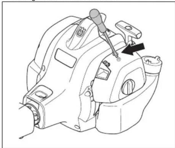
natural_image
Technical line drawing of a mechanical assembly with no visible text or symbols- Do a visual check of the spark arrester screen.
natural_image
Technical line drawing of a mechanical component with mounting holes and connectors (no text or symbols)a) Replace the spark arrester screen if it is damaged.
b) Clean the spark arrester screen if it is blocked.

CAUTION: If the spark arrester screen is blocked the product becomes too hot and this causes damage to the cylinder and piston.
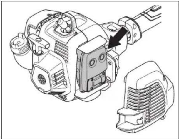
To clean the cooling system

CAUTION: A dirty or blocked cooling system can make the product too hot, which can cause damage to the product.
The parts of the cooling system are the air intake on the starter (A), the cooling fins on the cylinder (B) and the cylinder cover (C).
- Clean the cooling system with a brush weekly or more frequently if it is necessary.
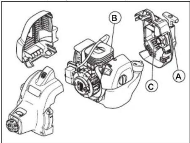
- Make sure that the cooling system is not dirty or blocked.
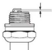
To examine the spark plug

CAUTION: Always use the recommended spark plug type. Incorrect spark plug type can cause damage to the product.
- Examine the spark plug if the engine is low on power, is not easy to start or does not operate correctly at idle speed.
• To decrease the risk of unwanted material on the spark plug electrodes, obey these instructions:
a) Make sure that the idle speed is correctly adjusted.
b) Make sure that the fuel mixture is correct.
c) Make sure that the air filter is clean.
- If the spark plug is dirty, clean it and make sure that the electrode gap is correct, refer to Technical data on page 22.
natural_image
Technical line drawing of a mechanical component with threaded body and shaft (no text or symbols)- Replace the spark plug if it is necessary.
Air filter
Remove dust and dirt from the air filter to keep it clean and prevent these problems:
• Carburetor malfunctions.
• Problems when you start the product.
- Loss of engine power.
- Increased wear to engine parts.
- Too much fuel consumption.
To clean the air filter
-
Remove the air filter cover and remove the filter.
-
Hit the filter against a flat surface to make the particles fall off.

CAUTION: Do not use solvent or compressed air to clean the air filter.
-
Put the air filter back. Make sure that the air filter fully seals against the air filter holder.
-
Put the air filter cover back.
Note: An air filter that is used for a long time cannot be fully cleaned. Replace the air filter at regular intervals. Always replace a damaged air filter.
Bevel gear 130L
The bevel gear is filled with the right quantity of grease at the factory. But, before you use the product, make sure that the bevel gear is 3/4 full with grease. Use Husqvarna special grease.
natural_image
Technical line drawing of a mechanical device with a hammer and base, showing no text or symbolsThe grease in the bevel gear does not need to be changed unless repairs are carried out.
Maintenance schedule
The following is a list of the maintenance steps that must be performed on the product. Most of the items are described in Maintenance on page 18
Note: The user must only carry out the maintenance and service work described in this operator's manual. More extensive work must be carried out by an authorized service workshop.
| Maintenance Daily Weekly Monthly | |||
| Clean the external surface. X | |||
| Make sure that the throttle trigger lock and the throttle works correctly from a safety point of view. | X | ||
| Do a check of the stop switch to make sure that it works correctly. X | |||
| Make sure that the cutting attachment does not rotate at idle speed. X | |||
| Clean the air filter. Replace if necessary. X | |||
| Examine the cutting attachment guard for damages and cracks. Replace the guard if it has been exposed to impact or is cracked. | X | ||
| Examine the trimmer head for damages and cracks. Replace if damaged. X | |||
| Make sure that the screws and nuts are tight. X | |||
| Examine the engine, the fuel tank and the fuel lines for leaks. X | |||
| Clean the cooling system. X | |||
| Examine the starter and the starter rope for damages. X | |||
| Examine the vibration damping elements for damages and cracks. X | |||
| Clean the outside of the spark plug. Remove it and do a check of the electrode gap. Adjust the gap to the correct distance (see, To examine the spark plug on page 19) or replace the spark plug. Make sure that the spark plug is fitted with a suppressor. | X | ||
| Clean the outside of the carburettor and the space around it. X | |||
| Do a check of the bevel gear to make sure that it is filled three-quarters with lubricant. Use special grease to fill if necessary. | X | ||
| Clean or replace the spark arrestor mesh on the muffler (only applies to mufflers without a catalytic converter). | X | ||
| Do a check of the fuel filter for contamination and the fuel hose for cracks or other defects (130L (LT13028CSHV). Replace if neccessary. | X | ||
| Do a check of all cables and connections. X | |||
| Do a check of the clutch, clutch springs and the clutch drum for wear. Replace if neccessary by an authorized service workshop. | X | ||
| Replace the spark plug. Make sure that the spark plug is fitted with a suppressor. | X | ||
| Check and clean the spark arrestor mesh on the muffler (only applies to mufflers without a catalytic converter). | X |
Troubleshooting
The engine does not start
| Check | Possible cause Procedure | |
| Starter pawls. The starter pawls cannot move freely. Remove the fuel type. Drain the fuel tank and fill with correct fuel. | starter cover and clean around the starter pawls. | |
| Let an approved service agent help you. | ||
| Fuel tank. Incorrect fuel type. Drain the fuel tank and fill with correct fuel. | fuel. | |
| Spark plug. The spark plug is dirty or wet. Make sure that the spark plug is dry and clean. | clean the spark plug. Make sure that the electrode gap is correct. Make sure that the spark plug has a suppressor. | |
| Refer to technical data for correct electrode gap. | ||
| The spark plug is loose. Tighten the spark plug. | ||
The engine starts but stops again
| Check | Possible cause Procedure | |
| Fuel tank. Incorrect fuel type. | Empty the fuel tank and fill it with correct fuel. | |
| Check Possible cause Procedure | ||
| Air filter. The air filter is clogged. Clean the air filter. | ||
Transportation and storage
Transportation and storage
- For storage and transportation of the product and fuel, make sure that there are no leaks or fumes. Sparks or open flames, for example from electrical devices or boilers, can start a fire.
• Always use approved containers for storage and transportation of fuel. -
Empty the fuel tank before transportation or long-term storage. Discard the fuel at an applicable disposal location.
-
Use the transportation guard on the product to prevent injuries or damage to the product. A blade that does not move can also cause serious injuries.
- Remove the spark plug cap from the spark plug.
- Attach the product safely during transportation.
Technical data
Technical data
| 130C (LT13028CCHV) 130L (LT13028CSHV) | |
| Engine | |
| Cylinder displacement, cu.in./cm 3 | 1.7/28 1.7/28 |
| Idle speed, rpm 2800–3200 2800–3200 | |
| Recommended max. speed, rpm 8000 8000 | |
| Speed of output shaft, rpm 8000 5472 | |
| Max. engine output, according to ISO 8893, kW/hp @rpm | 0.7/1.0 @ 8000 0.7/1.0 @ 8000 |
| Catalytic converter muffler Yes Yes | |
| Ignition system | |
| Spark plug Champion QCJ-8Y Champion QCJ-8Y | |
| Electrode gap, in./mm | 0.024/0.6 |
| Fuel and lubrication system | |
| Fuel tank capacity, US Pint/l | 1.12/0.5 |
| Weight | |
| Without fuel, cutting attachment and guard, lb/kg | 11.0/5.0 |
Accessories
Accessories
The accessories used in combination with the specified power heads have been evaluated to ANSI B175.3-2013 Grass Trimmers and Brushcutters
Safety Requirements. These combinations have been evaluated by Underwriters Laboratories Inc. (UL) and are consequently UL listed.
| 130C | ||
| Approved accessories Type Cutting | attachment guard, art. no. | |
| Blade shaft thread 3/8 R | ||
| Trimmer head RapidReplace | TM, T25, T35 (2.03–2.67 mm / .080–.105 in trimmer line) | 531 12 79-13 |
| 130L | ||
| Approved accessories Type Cutting | attachment guard, art. no. | |
| Blade shaft thread M10 | ||
| Trimmer head RapidReplace | TM, T25, T35 (2.03–2.67 mm / .080–.105 in trimmer line) | 501 13 67-03 |
| Approved accessories Art No. Cutting | attachment guard, art. no. | |
| J-handle set including grass blade Grass 255-4 1” (∅ 255 4-teeth) | 537 04 85-04 588 11 79-01 | |
The accessories are recommended for use in combination with the specified power heads and have been evaluated to applicable ISO- and EN safety requirement standards by the Swedish Machinery Testing Institute.
Contenido
Introducción.... 24
Seguridad....26
Montaje.... 32
natural_image
Line drawing of a person using a manual power shaver to cut a tree branch (no text or symbols)natural_image
Line drawing of a helmet and safety goggles (no text or symbols)natural_image
Line drawing of a mechanical device with no visible text or symbolsnatural_image
Line drawing of a mechanical component or device with no visible text or symbolsnatural_image
Line drawing of a pair of boots with visible branding and sole details (no text or symbols)natural_image
Technical line drawing of a mechanical device with no visible text or symbolsnatural_image
Technical line drawing of a mechanical component with a directional arrow indicating motion (no text or symbols)natural_image
Diagram of a mechanical device with directional arrows indicating motion or force (no text or symbols)natural_image
Pure mechanical component diagram without any text, numbers, or symbolsnatural_image
Illustration of a mechanical tool interacting with a curved component (no text or symbols visible)natural_image
Technical diagram of a mechanical assembly with arrows indicating motion or force direction (no text or symbols present)natural_image
Technical line drawing of a mechanical clamp or bracket assembly with no visible text or symbolsnatural_image
Line drawing of a mechanical device with labeled components (no text or symbols)natural_image
Technical line drawing of a mechanical component with an inset close-up showing a detail (no text or symbols)natural_image
Illustration of a mechanical clamp or bracket assembly with hands adjusting parts (no text or symbols)natural_image
Simple black-and-white icon of a fuel pump with a droplet and plus sign, no text or symbols present.natural_image
Line drawing of a mechanical component with no visible text or symbolsnatural_image
Technical line drawing of a mechanical component with an inset showing a close-up view of a hand holding a tool (no text or symbols present)natural_image
Illustration of a worker in safety gear handling equipment (no text or symbols)
natural_image
Technical line drawing of a mechanical component with a black arrow indicating a step, no visible text or symbolsnatural_image
Technical line drawing of a mechanical assembly with a tool inserted, showing no text or symbols.Para arrancar un motor caliente
natural_image
Illustration of a mechanical device with a circular symbol marked by a 'no' (no text or symbols present)natural_image
Line drawing of a mechanical tool with a handle and screw, showing a black arrow pointing to the handle (no text or symbols present)natural_image
Simple line drawing of a grassy slope with a small utility pole (no text or symbols)natural_image
Simple line drawing of a grassy field with a small plow and a tool, no text or symbols present.natural_image
Simple line drawing of a grassy field with a small mechanical component at the base (no text or symbols)natural_image
Illustration of a person using a tool to measure a mechanical component with dashed arrows indicating motion (no text or symbols)natural_image
Diagram of a grass sprayer with a butterfly wing, showing mechanical components and directional arrows (no text or symbols)
natural_image
Technical line drawing of a mechanical assembly showing three stages: top view, middle view, and bottom view with an upward arrow indicating motion (no text or symbols present)
natural_image
Line drawing of hands holding a mechanical component with a rotating arrow indicating rotation (no text or symbols)
natural_image
Illustration showing hands assembling a mechanical component with a downward arrow indicating assembly (no text or symbols present)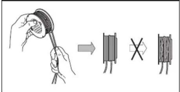

natural_image
Technical line drawing of a mechanical component with directional arrows indicating assembly or force (no text or symbols)natural_image
Technical line drawing of a mechanical assembly with a tool and arrow indicating a component (no text or symbols present)natural_image
Technical line drawing of a mechanical assembly with no visible text or symbolsnatural_image
Technical line drawing of a mechanical component with mounting holes and connectors (no text or symbols)natural_image
Technical line drawing of a mechanical component with threaded body and shaft (no text or symbols)natural_image
Technical line drawing of a mechanical device with a hammer and base, showing no text or symbolsnatural_image
Line drawing of a person using a shoveling machine to brush a tree (no text or symbols)natural_image
Line drawing of a helmet and safety goggles (no text or symbols)natural_image
Line drawing of a mechanical component or device (no text or symbols)natural_image
Line drawings of eyeglasses and accessories (no text or symbols)natural_image
Line drawing of a pair of boots with visible branding and sole details (no text or symbols)natural_image
Technical line drawing of a mechanical component with an arrow indicating direction (no text or symbols)natural_image
Diagram of a mechanical component with directional arrows indicating motion or force (no text or symbols)natural_image
Mechanical component diagram showing a lever mechanism with directional arrows indicating motion (no text or symbols)natural_image
Technical line drawing of a mechanical component with an arrow indicating direction (no text or symbols)natural_image
Illustration of a mechanical tool interacting with a base (no text or symbols visible)natural_image
Technical diagram of a mechanical assembly with arrows indicating motion or force direction (no text or symbols present)natural_image
Technical line drawing of a mechanical clamp or bracket assembly with mounting base (no text or symbols)natural_image
Line drawing of a mechanical device with labeled components and motion arrow (no text or symbols)natural_image
Technical line drawing of a mechanical component with an inset close-up showing a detail (no text or symbols)natural_image
Illustration of a mechanical clamp or bracket being adjusted, showing tool positioning and assembly (no text or symbols)natural_image
Simple black-and-white icon of a fuel pump with a droplet and plus sign (no text or symbols)natural_image
Line drawing of a mechanical component with no visible text or symbolsnatural_image
Technical line drawing of a mechanical component with an inset showing a close-up view of a component (no text or symbols present)natural_image
Illustration of a worker in safety gear handling equipment (no text or symbols)
natural_image
Technical line drawing of a mechanical component with a black arrow indicating a step or adjustment (no text or symbols present)natural_image
Diagram of a mechanical device with a circular symbol marked by a 'no' (no text or labels present)natural_image
Line drawing of a mechanical clamp or lever mechanism with a black arrow indicating the pivot point (no text or symbols present)natural_image
Simple line drawing of a grassy slope with a small utility pole (no text or symbols)natural_image
Simple line drawing of a grassy field with a tool, no text or symbols presentPour couper l'herbe
natural_image
Simple line drawing of a grassy field with a small mechanical component at the base (no text or symbols)natural_image
Illustration of a person holding a device with a dashed arrow indicating direction (no text or symbols)natural_image
Diagram of a grass sprayer with a butterfly wing, showing mechanical components and directional arrows (no text or symbols)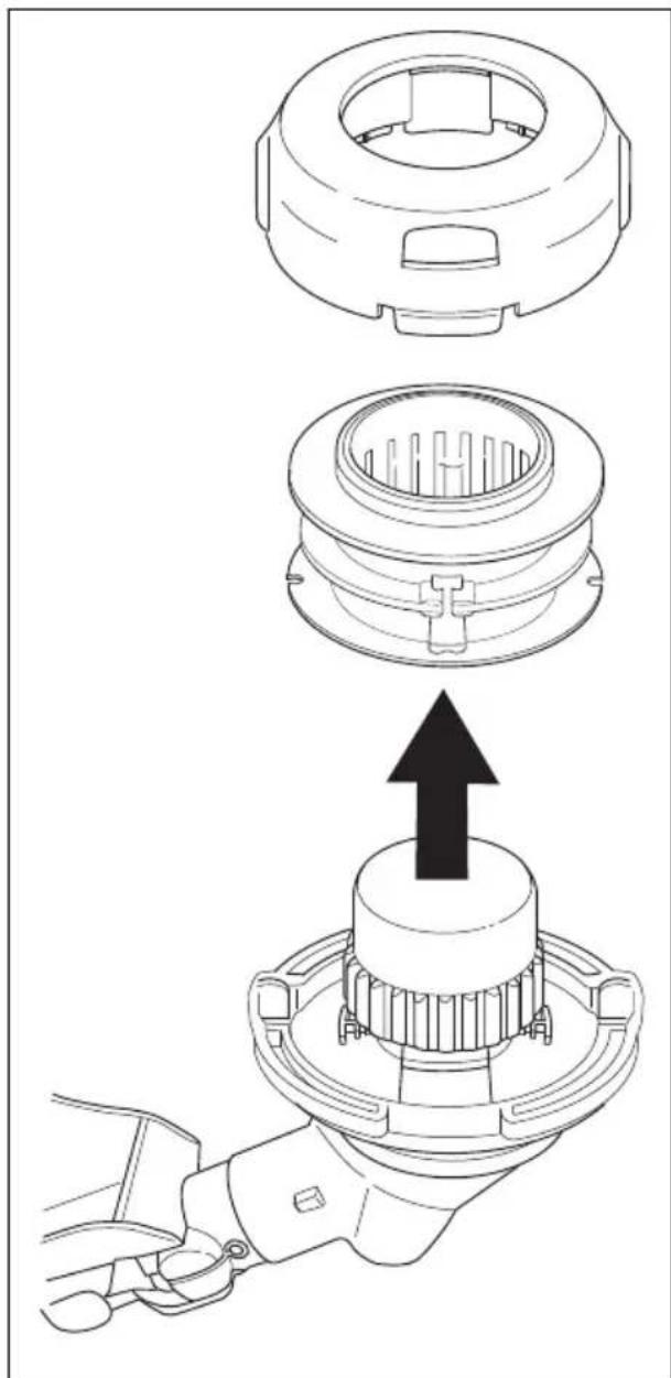
natural_image
Technical line drawing of a mechanical assembly showing three stages: top view, middle view, and bottom view with an upward arrow indicating motion (no text or symbols present)

natural_image
Line drawing of hands holding a mechanical component with a rotating arrow indicating rotation (no text or symbols)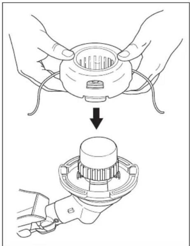
natural_image
Illustration showing hands assembling a mechanical component with a downward arrow indicating assembly (no text or symbols present)

natural_image
Technical line drawing of a mechanical component with directional arrows indicating assembly or force (no text or symbols)natural_image
Technical line drawing of a mechanical assembly with a tool and directional arrow (no text or symbols)natural_image
Technical line drawing of a mechanical assembly with no visible text or symbolsnatural_image
Technical line drawing of a mechanical component with mounting holes and connectors (no text or symbols)natural_image
Technical line drawing of a spark plug (no text or symbols)natural_image
Technical line drawing of a mechanical component with a hammer and base, showing no text or symbolsOriginal instructions


- Introduction
- Product description
- Intended use
- Product overview
- Symbols on the product
- EPA III
- California Proposition 65
- Safety
- Safety definitions
- Product liability
- General safety instructions
- Vibration safety
- Safety instructions for operation
- Personal protective equipment
- Safety devices on the product
- To do a check of the throttle trigger lockout
- To do a check of the stop switch
- To do a check of the cutting attachment guard
- To do a check of the vibration damping system
- Cutting attachment
- Grass trimmer head
- Fuel Safety
- Safety instructions for maintenance
- Assembly
- To attach the loop handle (130L)
- To attach the loop handle (130C)
- To attach the cutting attachment guard and the trimmer head (straight shaft)
- To attach the cutting attachment guard and trimmer head (curved shaft)
- Operation
- Fuel
- Premixed fuel
- To mix fuel
- Gasoline
- Two-stroke oil
- To fill the fuel tank
- To do before you operate the product
- To start a cold engine
- To start a warm engine
- About the surface
- To start the engine when the fuel is too hot
- To stop the product
- Grass trimming with a trimmer head
- To trim the grass
- To cut the grass
- To sweep the grass
- To extend the trimmer line
- To replace the trimmer line (130L)
- To examine and clean the trimmer head 130L
- Maintenance
- To adjust the idle speed
- To do a check of the muffler
- To clean the cooling system
- To examine the spark plug
- Air filter
- To clean the air filter
- Bevel gear 130L
- Maintenance schedule
- Troubleshooting
- Transportation and storage
- Technical data
- Accessories
- Contenido
- Para arrancar un motor caliente
- Pour couper l'herbe
Brand : HUSQVARNA
Model : 130C
Category : Brush cutter