37150 - Lighting Heitronic - Free user manual and instructions
Find the device manual for free 37150 Heitronic in PDF.
| Product type | Solar LED wall light with motion sensor |
| Brand | Heitronic |
| Model | 37150 |
| Dimensions (approx.) | 20 x 15 x 10 cm |
| Weight (approx.) | 0.5 kg |
| Power supply | 1 x Li-Ion battery 7.4V (rechargeable via built-in solar panel) |
| Bulb type | Integrated non-replaceable LED |
| Protection rating | IP54 (protected against water splashes and dust) |
| Protection class | III (extra low voltage) |
| Main functions | Automatic on at dusk, off at dawn, motion sensor, mode selection via switch |
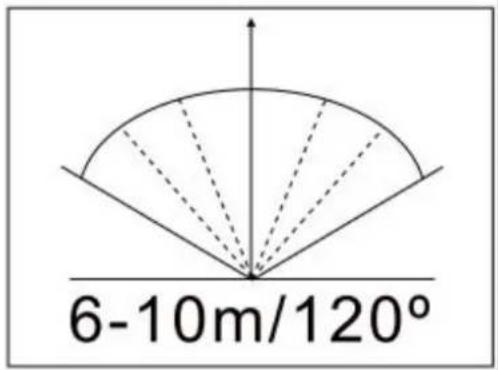
| Detection angle | Follow the indicated angles during installation |
| Lighting duration | Varies according to sunlight and selected mode |
| Maintenance and cleaning | Clean with a soft dry cloth; do not use abrasive products |
| Safety | Do not look directly at the LED; do not modify the product; replace the battery if it leaks |
| Spare parts and repairability | Replaceable battery (Li-Ion 7.4V); non-replaceable LED; no other spare parts available |
| General information | Outdoor use only; do not dispose of with household waste; follow recycling instructions |
Frequently Asked Questions - 37150 Heitronic
User questions about 37150 Heitronic
0 question about this device. Answer the ones you know or ask your own.
Ask a new question about this device
Download the instructions for your Lighting in PDF format for free! Find your manual 37150 - Heitronic and take your electronic device back in hand. On this page are published all the documents necessary for the use of your device. 37150 by Heitronic.
USER MANUAL 37150 Heitronic
natural_image
Line drawing of a two-tiered rectangular device with a central mounting hole (no text or symbols)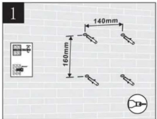
text_image
1 140mm 160mm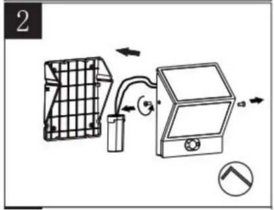
text_image
2
natural_image
Technical diagram of a mechanical cage or bracket with internal components and directional arrows, no readable text or symbols present.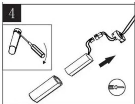
text_image
4
natural_image
Pure electrical connector diagram showing two connected components with bidirectional arrows indicating connection (no text or symbols)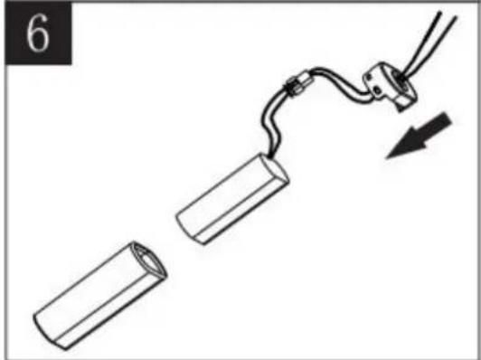
natural_image
Diagram showing two cylindrical objects connected by a wire with a cable, one being pulled and the other being pulled (no text or symbols)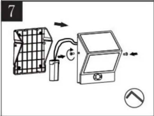
text_image
7
text_image
8 • Indicator A turn on, 11% light output after sunset, 100% light output when motion detected. Remain 11% after 1 minute if no new motion detected. • Click button for functional option A ○ B ○ • Indicator B turn on, lamp keep off after sunset, 100% when motion detected, remain off after 1 minute. • A/B indicators all off = stand-by mode, no power consumed
text_image
6-10m/120°GB Installation and Operating Instructions
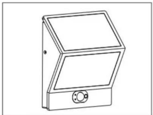
Solar LED wall light with motion sensor
Art. No. 37150
These operating instructions refer exclusively to the above products.
They contain important information for the start-up and handling of the product.
Therefore pay attention to these operating instructions, even if you pass this product on to third parties.
It is important, therefore, that these instructions are archived carefully for referring to information at a later stage.
1. Introduction
Dear customer, thank you for deciding to purchase our product.
You have acquired a product from Vollmer, which has been built according to the current state of technology.
The product fulfils the requirements of effective European and national guidelines.
To maintain the condition of the product and to ensure safe operation, you - as the user - must observe the instructions of this operation manual!
2. Safety Instructions / Warnings
- In the event of damage which is caused by not following these operating instructions, the warranty is rendered void.
• We do not accept liability for any consequential damage!
• Commissioning is strictly prohibited if there are any damages to the product!
- The product in its entirety must not be altered or modified. Alterations to the product invalidate the guarantee.
• The type plate must not be removed.
- Avoid staring directly into the LED when switched on
- Remove the batteries for longer periods out of use. Batteries may leak (risk of chemical burns)
3. Proper Use
• The solar light is designed for use in outdoor areas.
• The light switches on automatically at dusk and off again at dawn. (See below)
- High performance light diodes (LED) are used as the source of light. These LEDs guarantee high light intensity with low power consumption.
However, please note that little sunlight on the solar module and during the winter months can lead to impairment to the period of light/illumination.
Note: the period of light/light intensity heavily depends on the duration and intensity of the sun's rays during the day. The battery is not charged sufficiently in case of longer periods without sunlight so that constant availability for operation cannot be guaranteed. However, this does not mean that the solar light is defective.
Wait until the sun shines and the light will work again.
4. Before Installation/Commissioning
• The product must only be used outside its packaging.
• Take the product carefully out of the packaging.
- Make sure that the product has not been damaged during transport before taking it into operation. The light may not be operated if there are any damages to electrical parts.
- Keep packaging materials away from children and pets. Asphyxiation hazard!
5. Commissioning/Battery Change
- Observing the safety and warning instructions, place the solar light in the required position. Take account of the following detection radii before fixing the light to the required wall using appropriate screws:
- Now select the required operating mode by pressing the switch several times.
- Choose a suitable place with direct sunlight to charge the light up for the first time. Make sure that the sun is shining directly on the solar unit on the solar LED light. Shade on the solar unit impairs the battery's charging function.
- The solar LED light is charged using the solar panel on the top. It automatically switches on at dusk using the day/night sensor. Make sure that the day/night sensor on the top of the light is not influenced by another source. Otherwise it will not switch the light on at dusk.
- Switch the light off before changing the battery.
- Open the battery compartment cover on the back of the product and insert the battery.
- Close the compartment cover after inserting the battery.
- Press the switch to turn on.
natural_image
Line drawing of a two-tiered rectangular device with a central mounting hole (no text or symbols)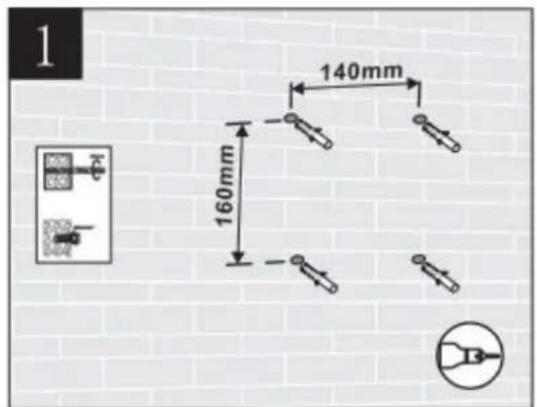
text_image
1 140mm 160mm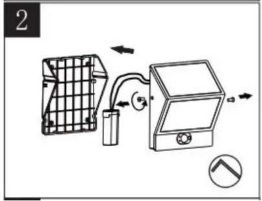
text_image
2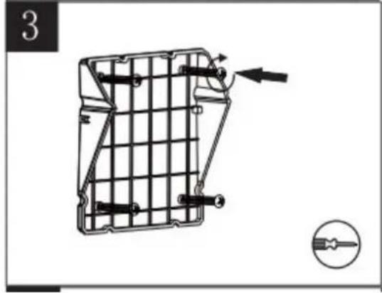
natural_image
Technical diagram of a mechanical cage or bracket with internal components and directional arrows, no visible text or symbols.
text_image
4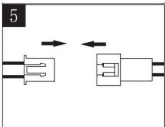
natural_image
Pure electrical connector diagram showing two connected components with bidirectional arrows indicating connection (no text or symbols)
natural_image
Diagram showing two cylindrical objects connected by a wire with a cable, one being pulled and the other being pulled (no text or symbols)
text_image
7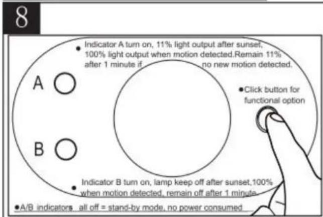
text_image
8 • Indicator A turn on, 11% light output after sunset, 100% light output when motion detected. Remain 11% after 1 minute if no new motion detected. • Click button for functional option A ○ B ○ • Indicator B turn on, lamp keep off after sunset, 100% when motion detected, remain off after 1 minute. • A/B indicators all off = stand-by mode, no power consumed
text_image
6-10m/120°6. Faulty Function
Lamp does not switch on
- An external source of light (e.g. street light) is simulating daylight and preventing the light from switching on. Place the light in a darker position
Lamp does not switch on or only briefly at dark.
• Light switched on?
• Battery low or defective. Replace the battery
7. Technical Data
| Article Supply Lamp | Protection Type | Protection Class | ||
| 37150 | 1x Li-Ion battery, 7.4 V | LED lamp, not replaceable | IP54 | III |
8. Care
- Disconnect the entire product from the mains first before cleaning or maintaining the product.
9. Waste Disposal
- Old electronic devices must be taken to public waste disposal sites and must not be put into general household waste.
- Batteries must not be put into general household waste. As an end consumer, you are legally obligated to return used batteries. You can return batteries free of charge after use to the point of sale or somewhere in your direct vicinity (e.g. in communal collection points or retail outlets).
- Batteries containing pollutants are marked with the symbol showing a crossed out bin and one of the chemical symbols Cd (=battery contains cadmium), Hg (=battery contains mercury) or Pb (=battery contains lead).
- Precautions must be taken against short-circuiting if the batteries are not fully discharged. Only discharged batteries may be put in the old battery containers you find in shops and at public disposal companies. Short-circuiting can be prevented by isolating the poles with sticky tape.
natural_image
Line drawing of a dual-panel electronic device with a circular button and mounting bracket (no text or symbols)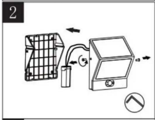
natural_image
Diagram of a device with grid panel, battery pack, and control panel connected by tubing (no text or symbols)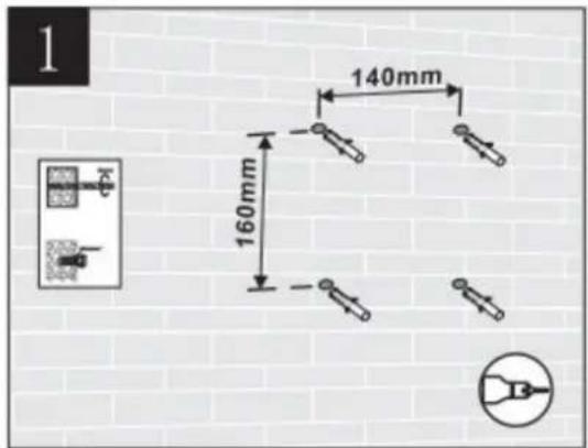
text_image
1 140mm 160mm 16mm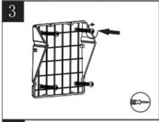
natural_image
Technical line drawing of a mechanical component with internal grid structure and directional arrows (no text or symbols)
text_image
4
natural_image
Pure electrical connector diagram showing two connected components with bidirectional arrows indicating connection (no text or symbols)
natural_image
Diagram showing two cylindrical objects connected by a wire with a cable, one being pulled and the other being pulled (no text or symbols)
text_image
7
text_image
8 • Indicator A turn on, 11% light output after sunset, 100% light output when motion detected. Remain 11% after 1 minute if no new motion detected. • Click button for functional option A ○ B ○ • Indicator B turn on, lamp keep off after sunset, 100% when motion detected, remain off after 1 minute. • A/B indicators all off = stand-by mode, no power consumed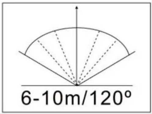
text_image
6-10m/120°natural_image
Line drawing of a mechanical device with two panels and a mounting bracket (no text or symbols)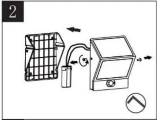
natural_image
Diagram of a device with grid panel, battery, and control panel connected by tubing (no text or symbols)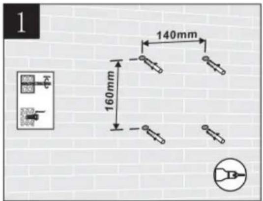
text_image
1 140mm 160mm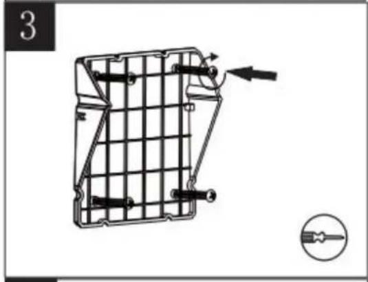
natural_image
Technical line drawing of a mechanical component with internal grid structure and directional arrows (no text or symbols)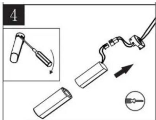
text_image
4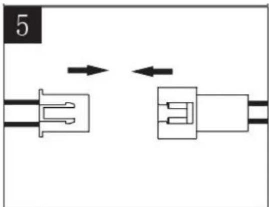
natural_image
Pure electrical connector diagram showing two connected components with bidirectional arrows indicating connection (no text or symbols)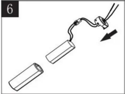
natural_image
Diagram of a cable being inserted into two cylindrical components, with an arrow indicating direction (no text or symbols)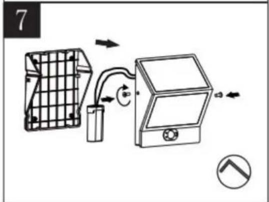
text_image
7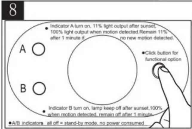
text_image
8 A ○ B ○ • Indicator A turn on, 11% light output after sunset, 100% light output when motion detected. Remain 11% after 1 minute if no new motion detected. • Click button for functional option • Indicator B turn on, lamp keep off after sunset, 100% when motion detected, remain off after 1 minute. • A/B indicators all off = stand-by mode, no power consumed