
286710 - Cooking appliance BARTSCHER - Free user manual and instructions
Find the device manual for free 286710 BARTSCHER in PDF.
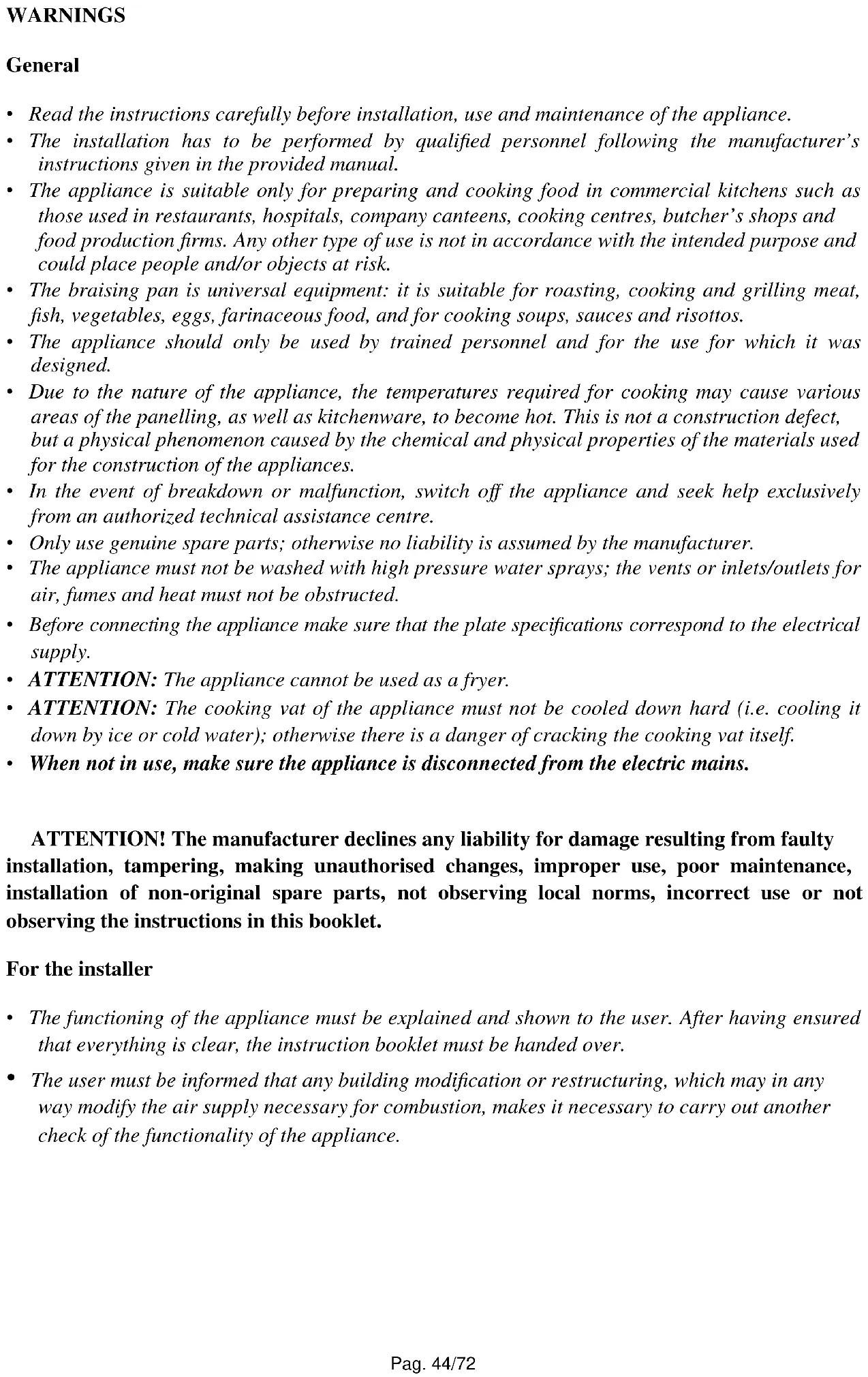
| Product type | Electric multifunction tilting skillet 1/2 module |
| Brand | Bartscher |
| Model | 286710 |
| Dimensions (W x D x H) | 400 x 700 x 845 mm |
| Pan dimensions (W x D x H) | 303 x 505 x 100 mm |
| Gross capacity of pan | 15 L |
| Usable capacity of pan | 12 L |
| Electrical power | 5 kW |
| Supply voltage | 230 V single-phase / 400 V three-phase |
| Frequency | 50/60 Hz |
| Power cable type | H07 RN-F 3x4 mm² (230 V) or 5x1.5 mm² (400 V) |
| Max. water supply pressure | 300 kPa |
| Water connection | UNI-ISO 7/1 R 1/2 |
| Cooking temperature range | 150 °C to 350 °C |
| Pan material | Stainless steel AISI 316 L (compound) |
| Heating type | Radiant heating elements |
| Safety thermostat | Manual reset |
| Tilting system | Manual |
| Drain system | Large opening with Teflon plug |
| Adjustable feet | Yes (adjustable height) |
| Cleaning | Warm water, neutral detergent, non-abrasive sponge |
| Installation | Under hood, respect safety distance of 100 mm from flammable walls |
| Prohibited use | As fryer or sudden cooling of the pan |
Frequently Asked Questions - 286710 BARTSCHER
User questions about 286710 BARTSCHER
0 question about this device. Answer the ones you know or ask your own.
Ask a new question about this device
Download the instructions for your Cooking appliance in PDF format for free! Find your manual 286710 - BARTSCHER and take your electronic device back in hand. On this page are published all the documents necessary for the use of your device. 286710 by BARTSCHER.
USER MANUAL 286710 BARTSCHER
CONDITIONS D'INSTALLATION
Lieud'st installation (fig. 9 pag. 5)
| Gas Type | Normal Capacity [kW] | Reduced Capacity [kW] | Diam. Main Injector [1/100 mm] | By-pass Diameter [1/100 mm] | Pilot Injectors [N°] | Air Regulation "x" [mm] |
| BRAISING PAN BURNER 1 UNIT | ||||||
| Liquid Gas PLG | 12,50 - | AL125 x 2 | 16.2 1.5 | |||
| (G30-G31) | ||||||
| Natural Methane Gas | 12,50 - | AL190 x 2 | 27.2 0.5 | |||
| (G20) | ||||||
(Table 3) BURNER FEATURES (IS - CAT. I_3P )
| Gas Type | Normal Capacity [kW] | Reduced Capacity [kW] | Diam. Main Injector [1/100 mm] | By-pass Diameter [1/100 mm] | Pilot Injectors [N°] | Air Regulation "x" [mm] |
| BRAISING PAN BURNER 1 UNIT | ||||||
| Liquid Gas PLG | 12,50 - | AL125 x 2 | 16.2 1.5 | |||
| (G31) | ||||||
(Table 4) BURNER FEATURES (CY, MT, HU - CAT. I_3 B/P )
| Gas Type | Normal Capacity [kW] | Reduced Capacity [kW] | Diam. Main Injector [1/100 mm] | By-pass Diameter [1/100 mm] | Pilot Injectors [N°] | Air Regulation "x" [mm] |
| BRAISING PAN BURNER 1 UNIT | ||||||
| Liquid Gas LPG | 12,50 - | AL125 x 2 | 16.2 1.5 | |||
| (G30-G31) | ||||||
(Table 5) BURNER FEATURES (HU - CAT. I_3 B/P )
| Gas Type | Normal Capacity [kW] | Reduced Capacity [kW] | Diam. Main Injector [1/100 mm] | By-pass Diameter [1/100 mm] | Pilot Injectors [N°] | Air Regulation "x" [mm] |
| BRAISING PAN BURNER 1 UNIT | ||||||
| Liquid Gas LPG | 12,50 - | 105R x 2 - | 16.2 1.5 | |||
| (G30-G31) | ||||||
(Table 6) BURNER FEATURES (LV - CAT. I_2H
(Table 7) BURNER FEATURES (NL - CAT. II2L3B/P)
| Gas Type | Normal Capacity [kW] | Reduced Capacity [kW] | Diam. Main Injector [1/100 mm] | By-pass Diameter [1/100 mm] | Pilot Injectors [N°] | Air Regulation “x” [mm] |
| BRAISING PAN BURNER 1 UNIT | ||||||
| Natural Methane Gas | 12,50 - | AL190 x 2 | 27.2 0.5 | |||
| (G20) | ||||||
| Gas Type | Normal Capacity [kW] | Reduced Capacity [kW] | Diam. Main Injector [1/100 mm] | By-pass Diameter [1/100 mm] | Pilot Injectors [N°] | Air Regulation "x" [mm] |
| BRAISING PAN BURNER 1 UNIT | ||||||
| Liquid Gas PLG | 12,50 - | AL125 x 2 | 16.2 1.5 | |||
| (G30-G31) | ||||||
| Natural Methane Gas | 12,50 - | AL195 x 2 | 27.2 0.5 | |||
| (G25) | ||||||
Table 8) BURNER FEATURES (CZ, SK - CAT. II2H3B/P)
| Gas Type | Normal Capacity [kW] | Reduced Capacity [kW] | Diam. Main Injector [1/100 mm] | By-pass Diameter [1/100 mm] | Pilot Injectors [N°] | Air Regulation “x” [mm] |
| BRAISING PAN BURNER 1 UNIT | ||||||
| Liquid Gas PLG | 12,50 - | 105 R x 2 | - 16.2 1 | |||
| (G30-G31) | ||||||
| Natural Methane Gas | 12,50 - | AL190 x 2 | 27.2 0.5 | |||
| (G20) | ||||||
Table 9) BURNER FEATURES (DK, EE, FI, HR, LT, BG, NO, RO, SE, SI, SK, TR - CAT. II2H3B/P)
| Gas Type | Normal Capacity [kW] | Reduced Capacity [kW] | Diam. Main Injector [1/100 mm] | By-pass Diameter [1/100 mm] | Pilot Injectors [N°] | Air Regulation "x" [mm] |
| BRAISING PAN BURNER 1 UNIT | ||||||
| Liquid Gas LPG | 12,50 - | AL125 x 2 | 16.2 1.5 | |||
| (G30-G31) | ||||||
| Natural Methane Gas | 12,50 - | AL190 x 2 | 27.2 0.5 | |||
| (G20) | ||||||
(Table 10) BURNER FEATURES (PL - CAT. II _2E3P )
| Gas Type | Normal Capacity [kW] | Reduced Capacity [kW] | Diam. Main Injector [1/100 mm] | By-pass Diameter [1/100 mm] | Pilot Injectors [N°] | Air Regulation "x" [mm] |
| BRAISING PAN BURNER 1 UNIT | ||||||
| Liquid Gas LPG | 12,50 - | AL125 x 2 | 16.2 1.5 | |||
| (G31) | ||||||
| Natural Methane Gas | 12,50 - | AL190 x 2 | 27.2 0.5 | |||
| (G20) | ||||||
WARNING
General
- Read the instructions carefully before installation, use and maintenance of the appliance.
- The installation has to be performed by qualified personnel following the manufacturer's instructions given in the provided manual.
- The appliance is suitable only for preparing and cooking food in commercial kitchens such as those used in restaurants, hospitals, company canteens, cooking centres, butcher's shops and food production firms. Any other type of use is not in accordance with the intended purpose and could place people and/or objects at risk.
- The braising pan is universal equipment: it is suitable for roasting, cooking and grilling meat, fish, vegetables, eggs, farinaceous food, and for cooking soups, sauces and risottos.
- The appliance should only be used by trained personnel and for the use for which it was designed.
- Due to the nature of the appliance, the temperatures required for cooking may cause various areas of the panelling, as well as kitchenware, to become hot. This is not a construction defect, but a physical phenomenon caused by the chemical and physical properties of the materials used for the construction of the appliances.
- In the event of breakdown or malfunction, switch off the appliance and seek help exclusively from an authorized technical assistance centre.
- Only use genuine spare parts; otherwise no liability is assumed by the manufacturer.
- The appliance must not be washed with high pressure water sprays; the vents or inlets/outlets for air, fumes and heat must not be obstructed.
- Before connecting the appliance make sure that the plate specifications correspond to the electrical supply.
- ATTENTION: The appliance cannot be used as a fryer.
- ATTENTION: The cooking vat of the appliance must not be cooled down hard (i.e. cooling it down by ice or cold water); otherwise there is a danger of cracking the cooking vat itself.
- When not in use, make sure the appliance is disconnected from the electric mains.
ATTENTION! The manufacturer declines any liability for damage resulting from faulty installation, tampering, making unauthorized changes, improper use, poor maintenance, installation of non-original spare parts, not observing local norms, incorrect use or not observing the instructions in this booklet.
For the installer
- The functioning of the appliance must be explained and shown to the user. After having ensured that everything is clear, the instruction booklet must be handed over.
- The user must be informed that any building modification or restructuring, which may in any way modify the air supply necessary for combustion, makes it necessary to carry out another check of the functionality of the appliance.
TECHNICAL FEATURES
The following instructions for set up and functioning refer to gas and mixed appliances belonging to categories I3B / P , II2H3+ , II2H3B / P , II2HS3B / P , III_1ab2H3B / P with a power pressure for Buthane/Propane (G30-G31) of 30/37 mbar, for Methane (G20-G25) of 20/25 mbar. The data plate (fig. 7, 8 - p. 4), showing all the information to refer to about the appliance, is situated inside the right or left side of the control panel, depending on the appliance model.
Appliances have been checked in accordance with the European directives below:
2006/95/EC - Low Tension (LVD)
2004/108/EEC - Electromagnetic Compatibility (EMC)
2006/42/EC - Machinery directive
2011/65/UE - Rohs
2009/42/CE - Gas Appliances
and the particular reference norms.
Declaration of compliance
The manufacturer declares that the appliances of their production are compliant with the above mentioned EEC directives and requires that installation be done observing the norms in force, with particular regard to the system of fume evacuation and air exchange.
DESCRIPTION OF APPLIANCES
Gas Braising Pan
Sturdy structure of stainless steel on four feet which make it possible to regulate the height. The outside finishing is of stainless steel with Chromium-Nickel 18/10.
The cooking vat is provided with a thermostatic safety gas tap which enables the regulation of the temperature in a range from 90^ to 300^ inclusive. Safety is ensured by means of a thermocouple which is kept active by the flame of the pilot burner.
The cooking vat is made of stainless steel with bottom made of duplex; it is characterized by a manual or motorized tilting system, depending on the appliance version. Heating is achieved by means of stainless steel tubular burners, suitable for proper functioning at the high temperatures to which they are exposed.
Electric Braising Pan
Sturdy structure of stainless steel on four feet which make it possible to regulate the height. The outside finishing is of stainless steel with Chromium-Nickel 18/10.
The cooking vat is provided with a thermostat which enables the regulation of the temperature in a range from 90^ to 300^ inclusive. Safety is ensured by means of a manually activating safety thermostat.
The cooking vat is made of stainless steel with bottom made of duplex; it is characterized by a manual or motorized tilting system, depending on the appliance version. Heating is achieved by means of high-performance radiating heating elements activated by a thermostat.
Electric multi-purpose bratt pan.
Sturdy structure of stainless steel on four feet which make it possible to regulate the height. The outside finishing is of stainless steel with Chromium-Nickel 18/10..
The cooking vat is made of stainless steel with an AISI 316 L (compound) bottom; it is provided with a large drain hole for draining food (in particular semi-liquid food) into the steel container, which is in the appliance cabinet. A Teflon plug closes the hole during the cooking.
The appliance is provided with a thermostat which enables the regulation of the temperature in a range from 150^ to 350^ inclusive. Safety is ensured by means of a manually activating safety thermostat.
Heating is achieved by means of radiating heating elements, thus granting cooking uniformity on the whole vat bottom.
PROVISIONS FOR INSTALLATION
Place (fig. 9, p. 5)
It is advisable to install the appliance in a well-ventilated room or under an extractor hood. The appliance may be installed as a single unit or together with others. In both cases, if it is installed near a wall of inflammable material, a minimum distance of 100mm from the side and back walls must be observed (as in picture 9 at page 5). In the event that it is not possible to observe this distance, protective measures must be taken (e.g. use of sheets of refractory material) which ensure that the temperature of the walls is within the established safety limits.
Installation
Installation operations, gas or voltage conversions to other than the original, starting up the installation or appliance, ventilation, letting out fumes, and maintenance must be done following the manufacturer's instructions and observing the norms in force, by qualified personnel, in compliance with the following provisions (GB):
Gas Safety (Installation and Use) Regulations, 1984
Health and Safety at Work Act, 1974
- Codes of Practice, BS6173, 1982
The Building Regulations, 1985
The Building Standards Regulations, 1981
For others countries follow the relevant local rules for:
Gas board rules
Building regulations and local fire prevention provisions
Safety norms in force
Provisions of the Gas supplying company
The Electrical Norms in force
The Fire Brigade rules
Fume evacuation
These appliances are Type "A" and therefore it is not necessary to connect them directly to an evacuation pipe for combustion products. The products of combustion, however, must be directed into suitable hoods or similar devices, connected to a reliably efficient chimney, otherwise directly outside. If this is not possible, it is acceptable the use of an extractor fan connected directly to the external environment with a capacity no lower than what is stated in table 1. This value must be increased by the air exchange necessary for the users' well-being, in accordance with the norms in force (approximately a total of 35m^3/h per kW of gas output installed).
INSTALLATION
Preliminary operations
Remove the appliance from its packaging and ensure that it is intact; if in doubt, do not use it but contact professionally qualified personnel. The packaging materials are compliant with environmental safety regulations. They can be stored without risk, or else should be disposed of in accordance with current national regulations, in particular those regarding nylon bags and polystyrene. After verifying that the appliance is in good conditions, the protective film may be removed. Clean the external parts of the appliance carefully with warm water and detergent, using a cloth to remove all remaining residues, and then dry it with a soft cloth. If there are still traces of glue, they can be removed using a suitable solvent (e.g. acetone). Under no circumstances should abrasive substances be used. After the installation the appliance should be levelled by lowering or raising the adjustable legs.
Gas Connection
Before connecting the appliance, it is necessary to check that the gas type available corresponds to the gas type the appliance has been set for. In the event that they do not correspond, it is necessary to proceed as described in the paragraph "Functioning with gas different from the setting". The connection to the threaded coupling, having a diameter of 34 inch and situated on the bottom of the appliance, may be fixed or mobile using a compliant rapid pipe fitting. If flexible piping is used, this must be in stainless steel and compliant with the norms. All the seals on the junction threads must be in guaranteed materials certified for use with gas. Before installing each single appliance, it is necessary to install a cut-off cock for rapid interruption of the gas supply, placed in an easily accessible position in such a way as to make it possible to turn off the gas supply when the appliance is not being used. When the connection has been completed, its tightness must be checked by using a leak-finder spray.
Electric connection
Before connecting the appliance, it is necessary to check that the voltage of the power supply available corresponds to the voltage the appliance has been set for. In the event that they do not correspond, if voltage change is possible, it is necessary to modify the connection as shown in the provided wiring diagram. The terminal blocks are situated behind the instrument board and it is possible to reach it by unscrewing the screws that fix the panel to the appliance. For the model 286710 - 286720: the terminal blocks (4) are placed under the base (3), as shown in picture 20 at page 7 and they can be reached by unscrewing the screws (2) that fix the yoke (1).
Moreover, the efficiency of the earth connection must be checked, that the earth conductor on the connecting side is longer than the other conductors, and that the connecting cable has a wire bunch adequate for the power absorbed by the appliance and is at least type H05 RN-F. As in international provisions, before installing the appliance a unipolar device must be installed with a contacts opening of at least 3mm that must not interrupt the YELLOW-GREEN earth wire. The device must be installed near the appliance, it must be approved and have adequate capacity for the absorption of the appliance (see technical features).
The appliance must be connected to the EQUIPOTENZIALE system. The connector is situated near the entry of the electric cable; it is marked by a label with the symbol shown in picture 10 (page 5).
When using a safety switch for fault currents, the following should be observed.
- According to current legislation, these kind of appliances can have a leakage current of 1mA per kW of rated power input with no maximum. It should also be noted that all fault current protection switches available on the market have a current tolerance of less than 50% ; therefore, a suitable switch should be chosen.
- Connect only one single appliance to each switch.
- In some cases, after long periods of inactivity or with a new installation, it is possible that the appliance trips the safety switch when it is turned on. The reason for this is usually moisture in the insulation. The problem can be solved by a short pre-heating that bypasses the safety thermostat.
Water supply connection
Connect the water inlet pipe to the water mains, in accordance with the norms in force.
Checking gas tightness and pressure (fig. 11, p. 5)
Before proceeding to check the pressure, it is necessary to check the tightness of the gas installation up to the nozzle with a leak-finder spray to ensure that no damage has been done to the appliance during transportation. Then it is possible to proceed with checking the inlet pressure, which is done by means of a gauge for liquids, either a "U" gauge or an electronic gauge with a minimum definition of 0.1 mbar. In order to carry out the reading, the screw (1) must be removed from the pressure outlet (2) and the rubber pipe of the gauge connected. Open the gas supply valve of the appliance, check the pressure output and close the valve. Remove the pipe of the gauge and put back the screws correctly into the pressure outlet. The pressure valve must be within the minimum and maximum values shown below:
| Type of gas | \( {\mathrm{P}}_{\mathrm{n}} \) [mbar] | \( {\mathrm{P}}_{\min } \) [mbar] | \( {\mathrm{P}}_{\mathrm{{MAX}}} \) [mbar] |
| G20 (Methane) 20 | 17 25 | ||
| G20 (Methane)* 25 | 2030 | ||
| G25 (Methane) 25 | 2030 | ||
| G30 (Butane) 30 | 2035 | ||
| G31 (Propane) 37 | 2545 | ||
| G110/G120 (town gas) | 8615 |
(*These gases belong to _2HS3B / P category, which is used only in Hungary)
If the pressure reading is not within the limits of the table, find out the cause. After solving the problem, check the pressure again.
Checking gas power
Normally it is sufficient to check that the nozzles installed are the right ones and that the burners function properly. If desired, further check the power absorbed by using the "Volumetric Method". Thanks to a chronometer and a counter, it is possible to read the volume of gas output to the appliance in time units. The right comparison volume [E] can be obtained with the formula shown overleaf in litres per hour (l/h) or in litres per minute (l/min), by dividing the nominal and minimum outputs (power) shown in the table of burner features for the lowest heat capacity of the type of gas foreseen for use with the appliance. This value can be found in the norm tables or it can be provided by the local gas supply company.
$$ \mathbf {E} = \frac {\text {P o w e r}}{\text {H e a t c a p a c i t y}} $$
The reading must be done when the appliance is already in function.
Checking pilot burner
Check the flame of the pilot burner, which must be neither too short nor too high but must lap the thermocouple and have a sharp form. Otherwise, it is necessary to check the size of the nozzle depending on the pilot version, as specified in the following paragraphs.
Checking regulation of primary air
All the main burners are provided with primary air regulation. Checking must be done observing the values shown in the air regulation column of the burner features tables. To regulate the primary air, proceed as shown in the following paragraphs.
ATTENTION! All the parts, protected and sealed by the manufacturer may not be regulated by the installer if not specifically indicated.
Joining appliances
Once the levelling and connection operations have been completed, the appliances can then be joined together. Unroll the sealing strip (1), which is included in the joining kit inside the appliance, and stick it to the end of the work surface, about 2 - 3mm from the edge (fig. 27, p. 8). Then place the units together. As shown in picture 28 at page 8, check the level (3) along the back edge of the units; place the joining plate (4) on the raised part of the unit tops and fix the M6 screws (supplied with the provided kit) with an Allen key (6).
Once the joining plate (4) has been fixed to the appliances, fine adjustment of the joint can then be made with the grub screw (7), located on the joining strip. This should be tightened well with an Allen key (8), as shown in picture 29 at page 8.
Then position the stainless steel joining plate cover (9) and fix it in place with an M4 screw (10) using a Phillips screwdriver (11).
Remove any traces of trimming that can be seen between the devices with a scraper.
REGULATIONS AND SUBSTITUTION FOR USING A DIFFERENT GAS THAN THE TYPE PROVIDED FOR
Functioning with different gas to the type provided for
In order to change to another gas type, it is necessary to substitute the nozzle in the main burners and pilot burner, following the indications given in the following paragraphs. The type of nozzle to install can be found in table 2. The nozzles for the main burner, marked with the relative diameter in hundredths, and those for the pilot burner, marked with a number, can be found in a transparent bag attached to the instruction booklet.
When the conversion is completed, check the tightness of the pipe fittings and that the ignition and functioning of both pilot burner and main burner - both at minimum and maximum - are correct. It may be necessary to check the output (power).
Substituting the burner nozzle (figg. 12-13-14, pp. 5, 6)
In order to replace the burner nozzle, remove the knobs (1) and the lifting crank (2); then remove the front panel (3) by unscrewing the 4 screws that hold it in its place (4). Unscrew the connection (5) that joins the ramp (6) to the electro-valve (7) and the screws (8) that fix the electro-valve to the appliance frame. After clearing the work area, loosen the screw (9) that blocks the primary air regulation, close the clamp wide (10); unscrew the nozzle (11) with a spanner and replace it with an appropriate nozzle for the gas type to be used as shown in table 2. Reassemble the nozzle, tightening it well and proceed with regulating the primary air, as indicated in the next paragraph. When all this is done, put back the parts previously removed.
Regulating the primary air of the burner (fig. 14, p. 6)
After substituting the burner nozzle, the primary air must be regulated. Therefore, loosen the screw (9) that fixes the bush (10); bring value "X" to the correct measurement, referring to table 2; tighten the screw (4) and check the accuracy of value "X".
Substituting the pilot burner nozzle (figg. 12-13-15, pp. 5, 6)
In order to replace the nozzle of the pilot burner, remove the knobs (1) and the lifting crank (2); then remove the front panel (3) by unscrewing the 4 screws that hold it in its place (4). Unscrew the connection (5) that joins the ramp (6) to the electro-valve (7) and the screws (8) that fix the electrovalve to the appliance frame, as shown in picture 13. Unscrew the fitting (12) which fixes the gas supply pipe of the pilot (13) and remove the nozzle (14). Substitute it with the nozzle suitable for the gas type to be used, as shown in table 2. Then proceed to reassemble the new nozzle, reposition the pipe and tighten the fitting fully. When all this has been done, put back the parts previously removed.
INSTRUCTIONS FOR USE
Gas Braising Pan (fig. 16, p. 6)
In order to switch on the braising pan burner, proceed in the following way:
- Turn the knob (1) from the off position to the ignition position*
- Press down the button;
- Press the piezoelectric lighter button (2) to light the pilot burner;
- Keep the knob pressed down until the thermocouple heats up, keeping the pilot on; this can be checked through the slit on the front of the appliance;
- Switch on the main burner by turning the knob to ;
- Adjust to the required temperature by using the thermostat control knob (3).
In order to switch off the main burner, turn the knob to the right into the ON position ( ); in order to switch off also the pilot burner, turn the knob again to the OFF position
Electric Braising Pan (fig. 17, p. 6)
In order to switch on the electric braising pan, proceed in the following way:
- Turn the thermostat knob (1) into the position which corresponds to the desired cooking temperature; the two lamps light go on: the green light stays on all the time to show that there is tension, while the orange one lights off as soon as the cooking vat reaches the required temperature.
In order to switch off the electric braising pan, turn the knob into the 0 position.
Manual Tilting (fig. 18, p. 6)
In manual versions the vat tilting is achieved through the use of the crank (1) placed on the front panel of the appliance. The cooking vat rises by turning the crank clockwise, while it lowers by turning the crank anti-clockwise.
Motorized Tilting (fig. 19, p. 7)
In motorized versions the vat tilting is achieved through the use of the selector (1) placed on the front panel of the appliance. The cooking vat rises by turning the selector upwards (arrow ), while it lowers by turning it downwards (arrow ).
Be careful with the tilting system when cleaning and doing maintenance.
ATTENTION! Only use the appliance under surveillance. Never heat the cooking vat when it is empty.
The appliance cannot be used as a fryer.
While working, the areas where to cook, grill etc. are hot and conduct heat: therefore, it is advisable to touch these areas only if properly protected.
If the food preparing requires the use of fats or oils, be careful with their overheating: therefore, this operation must always be carried out under surveillance.
If the lid is kept closed during cooking, be careful when you lift it: there is a risk to get burnt due to the steam produced inside the cooking vat.
Multi-purpose bratt pan (fig. 21, p. 7)
How to grill:
- Turn the knob (1) of the thermostat to the desired temperature;
- At the same time the green lamp (2) lights on to show that there is tension;
- The orange lamp (3) stays on until the appliance reaches the right temperature;
- Proceed with food cooking.
In order to switch off the appliance, turn the knob (1) into position 0.
Before starting the next working cycle, it is recommended to remove the cooking remains with the aid of a paddle or a cloth.
How to cook and stew:
- Close the drain hole with the Teflon plug;
- Turn the knob (1) of the thermostat to the desired temperature;
- At the same time the green lamp (2) lights on to show that there is tension;
The orange lamp (3) stays on until the appliance reaches the right temperature; - Proceed with food cooking.
In order to switch off the appliance, turn the knob (1) into position 0.
Remove the Teflon plug and ladle out the cooked food into the GASTRONORM container in the appliance cabinet. The use of a paddle may be needed, depending on the food density.
Before starting the next working cycle, it is recommended to remove the cooking remains with the aid of a paddle or a cloth.
ATTENTION! Only use the appliance under surveillance. Never heat the cooking vat when it is empty.
The appliance cannot be used as a fryer.
While working, the areas where to cook, grill etc. are hot and conduct heat: therefore, it is advisable to touch these areas only if properly protected.
If the food preparing requires the use of fats or oils, be careful with their overheating: therefore, this operation must always be carried out under surveillance.
If the lid is kept closed during cooking, be careful when you lift it: there is a risk to get burnt due to the steam produced inside the cooking vat.
Abnormal functioning
If for any reason, the appliance does not start up or stops working during use, check that the power supply and the control knobs are set correctly; if all is regular, call customer service.
Some problems and their possible solutions
Problem Possible solution
| The pilot burner does not light on | - Check that gas inlet pressure is the same as that shown in table at page 49 - Check that the nozzle of pilot burner is not blocked - Check that the igniter plug is well fixed and connected |
| - Check that the igniter plug is intact - Check that the igniter cable is intact - Check that the piezoelectric igniter is intact and functions correctly - Check the gas valve - Check that gas inlet pressure is the same as that shown in table at page 49 - Check that the flame of the pilot burner laps the thermocouple; if this is not the case, adjust the pilot burner through the regulating screw on the valve | |
| The pilot burner lights off after loosening the igniter knob | - Press the gas knob in its correct position - Change the thermocouple - Check if the valve magnetic group is rusted - Check the gas valve - Check that gas inlet pressure is the same as that shown in table at page 49 - Check that the gas nozzles are not blocked |
| The pilot burner stays on but the main burner does not light on | - Check that the burner holes are not blocked - Check that the gas pipe is not blocked - Check that the nozzles installed are in accordance to table 2-3-4-5-6-7-8-9-10 - Check the gas valve - Check that gas inlet pressure is the same as that shown in table at page 49 |
| Slow and/or inadequate heating | - Check that the nozzles installed are in accordance to table 2-3-4-5-6-7-8-9-10 - Check the gas valve - Check the power supply |
| No heating | - Check the condition of the heating element - Check the thermostat |
| No indicator light | - Check the power supply - Check the light bulb - Check the setting of the thermostat |
| Slow and/or inadequate heating | - Check the condition of the heating elements - Check the quantity of food to be cooked |
CARE AND MAINTENANCE OF THE APPLIANCE
Cleaning
ATTENTION! Before doing any cleaning, make sure that the appliance is disconnected from the electric mains and that the gas cut off valve is closed. During cleaning operations, avoid using direct or high pressure sprays of water on the appliance. Cleaning must be done when the appliance is cold. It is recommended not to cool down hard the cooking vat; it should not undergo thermal shocks due, for example, to the use of ice or extremely cold water. Otherwise, it is likely that the bottom of cooking vat will crack.
Steel parts can be cleaned with warm water and neutral detergent, using a cloth. The detergent should be suitable for cleaning stainless steel and should not contain any abrasive or corrosive substances. Do not use ordinary steel wool or anything similar, as this can deposit rust-forming iron particles, and avoid contact of iron objects with the stainless steel. It is also inadvisable to use sandpaper or emery paper. Pumice powder should only be used for heavily encrusted dirt; however, a synthetic abrasive sponge or stainless steel wool used in the direction of the glazed finish would be preferable. After washing, dry the appliance with a soft cloth.
When cleaning, abrasive powders of any type, chlorine-based detergents and bleach should all be avoided. Also avoid pouring cold liquids on appliances while they are hot, or cracks could form which could cause the appliance to become deformed or broken.
Stainless steel parts should not be exposed to prolonged contact with concentrated acid substances (e.g. vinegar, condiments, spice mixtures, concentrated kitchen salt...), as they can create chemical and physical conditions that damage the passivation of the steel. It is therefore advisable to remove these substances using clean water.
If the appliance is not in use for a long time, it is advisable to turn off the gas tap. Then disconnect the main electricity supply; wipe all stainless steel surfaces with a cloth soaked in Vaseline oil in order to give it a protective film; air the rooms now and again.
ATTENTION: Never use substances, detergents and other solutions containing chlorine or its byproducts.
In order to remove any possible scale-marks, do not use products containing salt or sulphuric acid; suitable products are to be found in the market or, alternatively, a solution diluted in acetic acid can be used.
While cleaning the appliance, do not use inflammable liquids.
Maintenance
ATTENTION! Before doing any kind of maintenance or repairs, make sure that the appliance is disconnected from the electric mains and that the gas cut off valve is closed.
The following maintenance operations must be carried out at least once a year by specialised personnel. It is advisable to have a maintenance contract.
- Check for correct functioning of all control and safety devices;
- Check for correct ignition of burners and proper functioning at minimum;
- Check the tightness of the gas pipes;
- Check the condition of the power cable.
SUBSTITUTING COMPONENTS
ATTENTION! Before doing any kind of substitutions, make sure that the appliance is disconnected from the electric mains and that the gas cut off valve is closed.
Safety valve (fig.12, p. 5 - figg. 22, 23, p. 7)
In order to replace the safety valve, remove the water and gas knobs and the crank; then remove the front panel by unscrewing the four screws that hold it in its place, as shown in figure 12. Unscrew consecutively the pipe union that leads to the burner (1), the pipe union of the pilot burner (2), the thermocouple (3), the ramp union (4) and the screws (5) that fix the support plate in position (8). Take out the valve group including connections and the bracket; unscrew the fixing screws (11) of the bracket (8) from the electro-valve (10). Then unscrew the connections (9) of the valve paying attention not to damage the thread (these pieces will be used again). Replace the part and proceed to reinstall everything following the inverse sequence. For better sealing, it is advisable to screw the connections (9) to the valve by interposing a clamping screw.
Thermocouple
In order to replace the safety valve, remove the water and gas knobs and the crank; then remove the front panel by unscrewing the four screws that hold it in its place. Then unscrew the fitting of the thermocouple on the cock and the fitting on the pilot unit; substitute the component.
Heating elements (fig.12, p. 5 - figg. 24-25, p. 7)
In order to replace the heating elements, lift up the cooking vat as high as possible; remove the lid of the heating element box (1) and the heating element box (2) by loosening the screws that hold it. Remove the heating element after disconnecting it. If replacement is difficult, it can be made easier by removing the control panel (6) and the front panel (7) (as shown in picture 12); and tilt the cooking vat towards the front after removing the pin (8) and the split pin (9). Take great care in doing this and only if it is absolutely necessary.
Electric components (Multi-purpose bratt pan)
In order to replace the selector, the thermostat, the lamps, the main terminal board, and the safety thermostat of the electric multi-purpose bratt pan, take out the control board. Disconnect the electric cables of the component and replace it. Then, connect the electric cables following the instructions of the wiring diagram.
Heating elements (Multi-purpose bratt pan) (fig. 26 - p. 8)
In order to replace the heating elements, remove the knobs and the control panel; then unscrew the covering fixing nuts. Take out the covering (1); disconnect the heating element to be replaced (2) and remove it.
Information for electrical and electronic devices used in EU countries

According to EU directives, devices marked with the following symbol may not be disposed of together with normal household waste.
To dispose of your used device, please use the locally available differentiated collection system or consult your retailer when you buy an equivalent product.
By actively using the provided collection systems, you are contributing to the reuse, recycling and enhancement of electrical or electronic devices and protecting the environment and health.
Abusive product disposal is punishable by law in accordance with current legislation.
WHEN SUBSTITUTING, ONLY ORIGINAL SPARE PARTS SUPPLIED BY THE MANUFACTURER MUST BE USED. THE OPERATION MUST BE CARRIED OUT BY AUTHORIZED PERSONNEL.
ATTENTION! In the event that components of the gas installation are substituted, it is necessary to check for tightness and the correct functioning of the various parts.
THE MANUFACTURER RESERVES THE RIGHT TO WITHOUT NOTICE MODIFY THE FEATURES OF THE APPLIANCES DESCRIBED IN THIS MANUAL.

- CONDITIONS D'INSTALLATION
- Lieud'st installation (fig. 9 pag. 5)
- WARNING
- General
- For the installer
- TECHNICAL FEATURES
- Declaration of compliance
- DESCRIPTION OF APPLIANCES
- Gas Braising Pan
- Electric Braising Pan
- Electric multi-purpose bratt pan.
- PROVISIONS FOR INSTALLATION
- Installation
- Fume evacuation
- Preliminary operations
- Gas Connection
- Electric connection
- Water supply connection
- Checking gas tightness and pressure (fig. 11, p. 5)
- Checking gas power
- Checking pilot burner
- Checking regulation of primary air
- Joining appliances
- REGULATIONS AND SUBSTITUTION FOR USING A DIFFERENT GAS THAN THE TYPE PROVIDED FOR
- Functioning with different gas to the type provided for
- Substituting the burner nozzle (figg. 12-13-14, pp. 5, 6)
- Regulating the primary air of the burner (fig. 14, p. 6)
- Substituting the pilot burner nozzle (figg. 12-13-15, pp. 5, 6)
- INSTRUCTIONS FOR USE
- Gas Braising Pan (fig. 16, p. 6)
- Electric Braising Pan (fig. 17, p. 6)
- Manual Tilting (fig. 18, p. 6)
- Motorized Tilting (fig. 19, p. 7)
- Multi-purpose bratt pan (fig. 21, p. 7)
- How to grill:
- Abnormal functioning
- Problem Possible solution
- CARE AND MAINTENANCE OF THE APPLIANCE
- Cleaning
- Maintenance
- SUBSTITUTING COMPONENTS
- Thermocouple
- Electric components (Multi-purpose bratt pan)
- Heating elements (Multi-purpose bratt pan) (fig. 26 - p. 8)
Brand : BARTSCHER
Model : 286710
Category : Cooking appliance