Solamagic SM1000W - Heating Etherma - Free user manual and instructions
Find the device manual for free Solamagic SM1000W Etherma in PDF.

User questions about Solamagic SM1000W Etherma
0 question about this device. Answer the ones you know or ask your own.
Ask a new question about this device
Download the instructions for your Heating in PDF format for free! Find your manual Solamagic SM1000W - Etherma and take your electronic device back in hand. On this page are published all the documents necessary for the use of your device. Solamagic SM1000W by Etherma.
USER MANUAL Solamagic SM1000W Etherma
natural_image
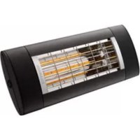
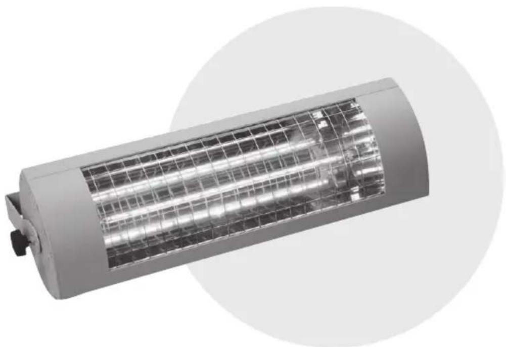
Exterior view of a cylindrical industrial lamp or fixture with grid-patterned panel (no visible text or symbols)SOLAMAGIC
natural_image
Technical line drawing of a mechanical bracket or support structure (no text or symbols)natural_image
Technical line drawing of a cylindrical mechanical component with internal grid structure and mounting bracket (no text or symbols)
natural_image
Isometric line drawing of a mechanical bracket with mounting holes (no text or symbols)natural_image
Technical line drawings of mechanical components including rods, pulleys, and a lock mechanism (no text or symbols)natural_image
Technical line drawing of a mechanical device with exploded view, showing components like handle, shaft, and housing (no text or labels)natural_image
Exterior view of a cylindrical industrial lamp or fixture with grid-patterned panel (no visible text or symbols)SOLAMAGIC
natural_image
Technical line drawing of a mechanical bracket or support structure (no text or symbols)natural_image
Technical line drawing of a cylindrical mechanical component with internal grid structure and mounting bracket (no text or symbols)
natural_image
Isometric line drawing of a mechanical bracket with mounting holes (no text or symbols)natural_image
Technical line drawings of mechanical components and rods, no text or symbols presentnatural_image
Technical line drawing of a mechanical device with exploded view, showing components like handle, shaft, and housing (no text or labels)natural_image
Exterior view of a cylindrical industrial lamp or fixture with grid-patterned panel (no visible text or symbols)SOLAMAGIC
Monterings- og
brugsanvisning for infrarød radiator
500 W, (IR 02004 / IR 02016)
1000 W, (IR 02007 / IR 02010)
1400 W kompakt, (IR 02001)
1400 W Basic, ECO+, (IR 03001 / IR 03038)
2000 W Basic, (IR 03002)
2000 W Basic, ECO+, (IR 04002 / IR 04039)
2000 W RC, ECO+, (IR 04003)
2000 W IP65 ECO+, (IR 04006)
2800 W, (IR 04009)
Indholdsfortegnelse
natural_image
Technical line drawing of a mechanical bracket or support structure (no text or symbols)natural_image
Technical line drawing of a cylindrical mechanical component with internal grid structure and mounting bracket (no text or symbols)
natural_image
Isometric line drawing of a mechanical bracket with mounting holes (no text or symbols)natural_image
Technical line drawings of mechanical components and railings (no text or symbols)
natural_image
Simple line drawing of a mechanical component with a cylindrical shaft and flange (no text or symbols)natural_image
Technical line drawing of a mechanical device with exploded view, showing components like handle, shaft, and housing (no text or labels)natural_image
Exterior view of a cylindrical industrial lamp or fixture with grid-patterned panel (no visible text or symbols)SOLAMAGIC
natural_image
Isometric line drawing of a metal L-shaped bracket with mounting holes (no text or symbols)1. For varmeovn med bøyle
natural_image
Technical line drawing of a cylindrical mechanical component with internal grid structure and mounting flanges (no text or symbols)

natural_image
Isometric line drawing of a mechanical bracket with mounting holes (no text or symbols)natural_image
Technical line drawings of mechanical components including rods, pulleys, and a lock mechanism (no text or symbols)
natural_image
Simple line drawing of a mechanical component with a cylindrical shaft and flange (no text or symbols)natural_image
Technical line drawing of a mechanical device with exploded view, showing components like handle, shaft, and housing (no text or labels)
natural_image
Technical line drawing of a cylindrical mechanical component with mounting brackets (no text or symbols)natural_image
Exterior view of a cylindrical industrial lamp or fixture with a grid-patterned panel (no visible text or symbols)natural_image
Isometric line drawing of a metal L-shaped bracket with mounting holes (no text or symbols)natural_image
Technical line drawing of a cylindrical mechanical component with internal grid structure and mounting flanges (no text or symbols)
natural_image
Isometric line drawing of a mechanical bracket with mounting holes (no text or symbols)natural_image
Technical line drawings of mechanical components and rods, no text or symbols present
natural_image
Simple line drawing of a mechanical component with a cylindrical shaft and flange (no text or symbols)natural_image
Technical line drawing of a mechanical device with exploded view, showing components like handle, shaft, and housing (no text or labels)
natural_image
Technical line drawing of a cylindrical mechanical component with mounting brackets (no text or symbols)natural_image
Exterior view of a cylindrical industrial lamp or fixture with grid-patterned panel (no visible text or symbols)SOLAMAGIC
natural_image
Isometric line drawing of a mechanical support bracket (no text or symbols)natural_image
Technical line drawing of a cylindrical mechanical component with internal grid structure and mounting bracket (no text or symbols)
natural_image
Isometric line drawing of a mechanical bracket with mounting holes (no text or symbols)natural_image
Technical line drawings of mechanical components and rods, no text or symbols present
natural_image
Simple line drawing of a mechanical component with a cylindrical shaft and flange (no text or symbols)natural_image
Technical line drawing of a mechanical device with exploded view, showing components like handle, shaft, and housing (no text or labels)
natural_image
Technical line drawing of a cylindrical mechanical component with mounting brackets (no text or symbols)natural_image
Exterior view of a cylindrical industrial lamp or fixture with grid-patterned panel (no visible text or symbols)SOLAMAGIC
Installation and Instruction Manual for Infrared Heaters
500 W, (IR 02004 / IR 02016)
1000 W, (IR 02007 / IR 02010)
1400 W kompakt, (IR 02001)
1400 W Basic, ECO+, (IR 03001 / IR 03038)
2000 W Basic, (IR 03002)
2000 W Basic, ECO+, (IR 04002 / IR 04039)
2000 W RC, ECO+, (IR 04003)
2000 W IP65 ECO+, (IR 04006)
2800 W, (IR 04009)
Contents
Safety and operating instructions 87
Scope of supply 88
Installation instructions....89
Initial operation....94
Cleaning instructions....94
Troubleshooting 95
Guarantee conditions....96
Additional instructions....97
Appendices
- Appendix 1: Surface mounted heaters Technical data, safety distances
AX
- Appendix 2: Ceiling mounted heaters Technical data, safety distances
AX
- Radiation diagrams
AX
Safety and operating instructions
Please observe the following instructions:
Carefully read through the instruction manual prior to installation and store the manual safely.
This heater is meant for outside use by adults. It is not meant to be used for indoor heating to create a pleasant temperature level.
Children must not play with the heater.
Children younger than 3 years old must be kept away from the heater unless they are continuously monitored.
Caution - Some parts of this product can become very hot and cause burns. Special care is required when children and vulnerable persons are present.
- Installation tasks must be properly carried out by a qualified person in accordance with VDE 0100 installation instructions (if applicable, also including Parts 559 and 701).
- When carrying out any work, always switch the system to a zero-volts state (disconnect mains plug; circuit-breaker off). Switch on the heater only after all cables have been completely connected.
- The domestic installation for the power supply of the heater must be designed with a switch and secured with a fuse of at least 16A slow (type C16A).
- Do not install directly under sockets, junction boxes, switches or electrical cabling.
- Electrical sockets may only be located in the positions specified in Appendix 1.
- Do not mount the radiant heater close to curtains or combustible materials in accordance with VDE 0100, Part 559.
- The device meets the minimum protection class IP 24, if all connectors (device plug, plugs for expansion components) are plugged in and it is approved for outdoor use.
- Never leave the heater unattended.
- Do not cover the heater when it is switched on or still hot; there is a risk of fire.
- To adjust the radiation direction, switch the heater off and allow to cool.
- Do not look directly at an operating IR halogen lamp for a long period and from a short distance.
-
IR halogen lamps are sensitive to direct skin contact (do not touch with bare fingers). Grease or other contamination can be removed with an alcohol-soaked cloth.
-
To maintain the service life of the IR halogen lamp, it must be protected against vibrations, impacts and contaminants such as acids, ammonia, cement dust, etc.
- The IR halogen lamp must be protected against mechanical loading. It must be replaced, if discolouration (dark spots, deformation) becomes apparent or the rated life time is reached.
- Damaged equipment elements such as lead, rocker switch, sealing collar or heating tube must always be replaced. The unit must be immediately dismantled and stored dry.
- Repair work (replacement of a defective power lead of a defective heating tube or the like) must only be carried out by the customer service of the manufacturer or an authorised dealer.
- Cleaning and maintenance work must only be carried out by adults with sufficient expertise.
Scope of supply
IR radiant heater
Bracket fitted on the heater or included in the set
Installation and Instruction Manual
Installation instructions
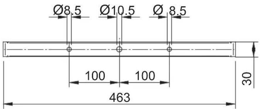
- The heater must only be installed using suitable fastenings (e.g. use M6x60 bolts with steel anchors in a stone or concrete substrate) on a firm, load-bearing, standard, flame-resistant or non-combustible substrate.
- If heater and socket are not installed on the same surface, it must be ensured that the field of radiation cannot be directed towards the socket. Failing this, it must be ensured that the socket cannot heat up to more than 70°C during heater operation.
- When mounted on a sloping ceiling, IR radiant heaters must be fitted with a „bottom“ power cord arrangement.
- The safety distances given in Appendixes 1 and 2 must be observed.
- The area in which the heat acts can be estimated from the radiation diagram (Appendix 3). The diagram shows the sizes of the irradiated areas at various distances from the radiant heater and in each case the maximum radiation intensity.
• Installation height: at least 1.80 m above the ground
natural_image
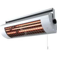
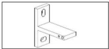
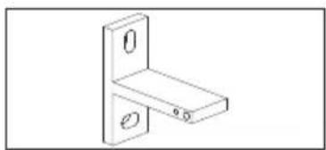
Isometric line drawing of a mechanical support bracket (no text or symbols)1. For radiant heaters with a bracket
- Fasten the bracket taking into consideration the safety distances (Appendix 1) and safety and operating instructions.
- Unscrew the star grip nuts and hexagon nut from the threaded spindles
- Mount the heater while slightly bending the bracket
- On one side, screw the hexagon nut on to the threaded bolt and tighten against the bracket
- Set the radiating angle as required
- Tighten the M6 nut with a 10 mm open-ended spanner.
- Screw the star grip nuts in place on both sides.
natural_image
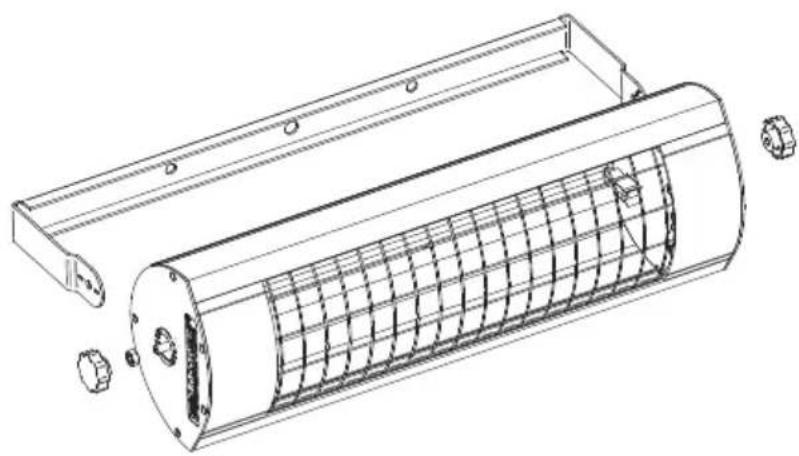
Technical line drawing of a cylindrical mechanical component with internal grid structure and mounting bracket (no text or symbols)
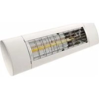
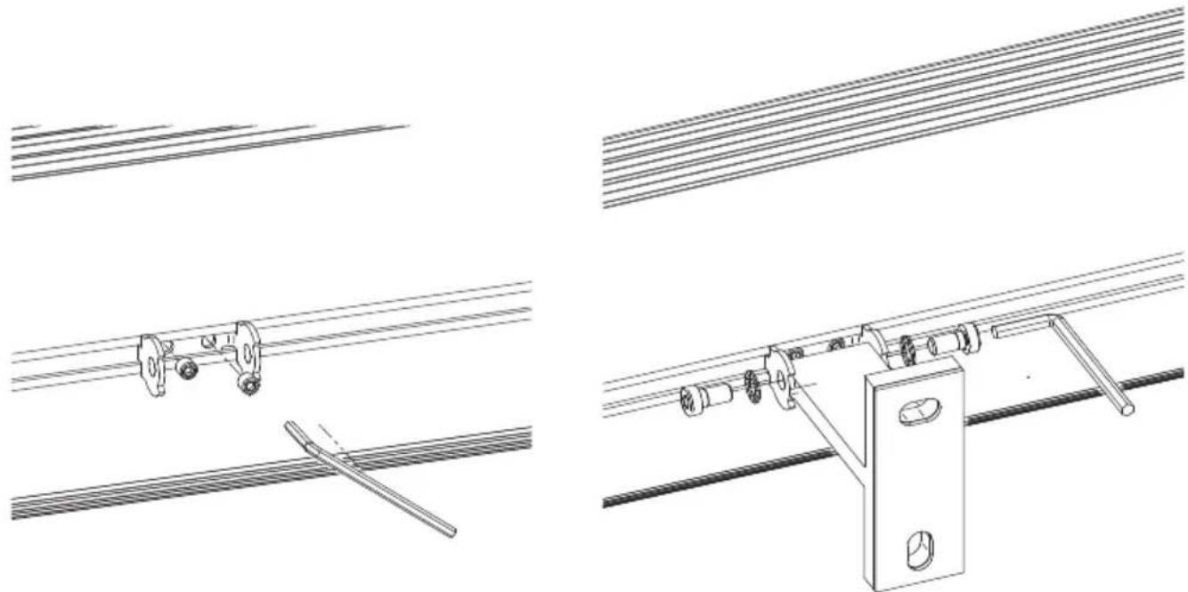
2. For radiant heaters with a T-bracket
natural_image
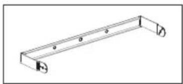
Isometric line drawing of a mechanical bracket with mounting holes (no text or symbols)- Mount the T-bracket with the underlying silicone plate on the fastening surface using 2 screws while adhering to the safety distances and safety instructions (see Appendix 1)
- Centre the clamping slide on the heater and secure by tightening the clamping screws.
- Position the heater on the T wall bracket using the clamping slide. Insert the M6 screws, complete with 6.4 mm serrated washer, on the sides through the clamping slide into the T wall bracket, then manually tighten.
- Position the heater so that it radiates in the desired direction and then tighten the two M6 screws using a 5 mm Allen key.
natural_image
Technical line drawings of mechanical components and rods, no text or symbols present
natural_image
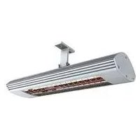
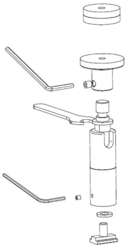
Simple line drawing of a mechanical component with a cylindrical shaft and flange (no text or symbols)3. For radiant heaters with pivoting hinges
- Determine the appropriate mounting separation of the pivoting hinges on the heater.
- Secure the ceiling plates at the selected separation using suitable fasteners on the wall/ceiling.
ATTENTION!
With ceiling mounting the supplied insulating washers must be installed between ceiling and ceiling plate.
- Tighten the hinges on the t-nuts until they can no longer move relative to the heater, tighten the M3 grub screws.
- Adjust the hinges until the desired tilting direction is achieved.
- Position and tighten the M5 grub screws in the ceiling plates.
natural_image
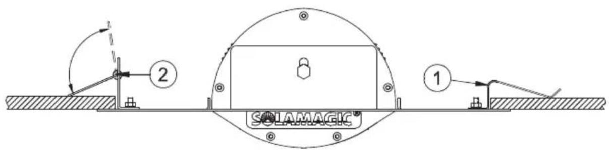
Technical line drawing of a mechanical device with exploded view, showing components like handle, shaft, and housing (no text or labels)4. For radiant heaters with a ceiling installation frame
General instructions
- The installation must not change or impair the existing ceiling stand.
- The electrical connection must be made outside the installation frame (inspection access).
- The minimum distances given in appendix 2 indicate the free space for air circulation. These must not be reduced or covered by insulation or similar.
Installation steps:
- Create a ceiling cut-out with the dimensions given in appendix 2.
- Connect the heater to the electricity.
- Insert the heater with the flat springs (1) in the ceiling cut-out, press the coil spring (2) back at the installation frame and also insert this side in the ceiling cut=out.
- Position the retaining springs (2) against the inside of the ceiling cut-out.
5. Other attachment methods
Please observe the special assembly instructions supplied with the additional accessories.
Initial operation
The heater must be connected to the mains. For those models without a switch, heating starts as soon as the plug is plugged into the socket. For models with a switch or a wireless switch, heating starts when the switch is turned on or via the remote control.
If necessary see also the separate operating instructions for the remote control.
Cleaning instructions
- Disconnect the heater from the mains.
- Allow the casing to cool.
- Wipe the casing clean with a moist, soft cloth. Do not use any detergent.
Never immerse the heater in liquids nor spray-wash it.
Possible discoloration of the protective grille due to heat effects results from normal physical processes and is not a defect.
Troubleshooting / help
Problem: The heater will not switch on.
- In the case of switch-activated models, the switch must be switched on after connection to the mains.
- Have you checked your fuse rating? You require a 16 amp slow fuse for trouble-free operation of your heater.
- Please check whether the IR halogen lamp is broken. If yes, please contact either customer service or the manufacturer.
Problem: The heater does not provide adequate heating.
- Check the radiation angle. The objects to be heated must be located in the direct radiation field.
- Check the distance to the heater and its installation height.
- The heater output is insufficient. Compare the heatable area in the technical data.
Problem: The IR halogen lamp no longer generates any heat.
• The average service life of IR halogen lamps is 5000 hours.
- If the useful service life has elapsed, please contact either customer service or the manufacturer.
Guarantee conditions for Solarmagic heaters
We offer a guarantee for the heaters portrayed in this manual in accordance with the following conditions:
- We will repair, free of charge, in accordance with the following provisions, damage or defects to the heater, which can be proven to be due to a factory defect, if they are reported to us immediately upon discovery on the heater. The duration of the guarantee for the heater is 2 years, for heaters labelled ECO+ we offer a guarantee extended by 1 year, that is a total of 3 years. The duration of the guarantee for the heating tube is 12 months up to a maximum 5000 operating hours within this period.
The guarantee does not cover minor deviations from the design properties that are irrelevant for the value and usability of the heater. Likewise the guarantee does not cover damage caused by exceptional climatic conditions, abnormal environmental conditions or unsuitable operating conditions. Your dealer will be happy to advise about heater versions for use in such cases. No guarantee can be given if the damage or defects on the heater arise from faulty installation or failure to observe the operating instructions.
-
The guarantee is fulfilled in that defective heaters will be repaired, or replaced by flawless heaters, at our discretion, and free of charge. Heaters for which a performance of guarantee is claimed with reference to this guarantee, must be to be handed over or sent to the manufacturer or an authorized service centre. End consumer labour and material costs are not refunded. Proof of purchase with the date of purchase and/or delivery date plus a detailed description of the fault must always be presented.
-
Any guarantee claim becomes void if repairs or adjustments are made by persons who are not authorised by us or if our heaters are provided with spare parts, supplementary parts or accessories that are not original parts, and have caused a defect. The same applies if the name plate or the heater number has been removed or rendered illegible.
-
Excluded from this guarantee are damage or defects from incorrect connection, improper handling, mechanical damage, particularly to the heating tube, and failure to observe the installation and operating instructions. We accept no liability for consequential damage.
-
Guarantee performances do not extend the guarantee period nor do they initiate a new guarantee period. The guarantee period for any fitted spare parts ends with the guarantee period for the heater as a whole. If a defect or deficiency cannot be eliminated or the rectification of defects is declined by us or unreasonably delayed, an equivalent replacement will be delivered, free of charge, upon the
request of the customer. In case of replacement, we reserve the right to enforce a reasonable usage charge for time of use up until the time of replacement. Re-placed heaters become our property.
- The guarantee only comes into force when the customer has registered their heater with the manufacturer by means of the guarantee card.
These guarantee conditions apply from 01/01/2015 for heaters purchased in a country of the European Union, even if you use it in a foreign country. The guarantee conditions have no effects on the statutory guarantee claim.
Additional instructions
Subject to technical changes
These products are „Made in Germany“.
For more products and accessories from SOLAMAGIC ^® , see:
www.SOLAMAGIC.com
Please note the following terminology in the appendix:
Appendix 1: Surface mounted heaters - technical data, safety distances
| 1 | Heater type | 8 | Dimensions (mm) |
| 2 | Product group | 9 | Weight (kg) |
| 3 | Power connection | 10 | Average service life (h) |
| 4 | Degree of protection | 11 | Distance (mm) |
| 5 | Power (W) | 12 | Ceiling installation |
| 6 | Protection rating | 13 | Wall installation |
| 7 | Marking A Distance to the side wall | ||
| C | Distance to the wall behind D Distance to ceiling | ||
| E | Distance to the irradiated surface | ||
Appendix 2: Ceiling mounted heaters - technical data, safety distances
| 1 | Heater type | 7 | Marking |
| 2 | Product group | 9 | Weight (kg) |
| 3 | Power connection | 10 | Average service life (h) |
| 4 | Degree of protection B1 Cut-out width | ||
| 5 | Power B2 Frame width | ||
| 6 | Protection rating L1 Cut-out length | ||
| H3 | Ceiling separation L2 Frame length | ||
| A | Distance to the side wall E | Distance to the irradiated surface |
Appendix 3: Radiation diagrams
| 1 | Maximum power | 2 | Heated surface |
natural_image
Exterior view of a cylindrical industrial lamp with grid-patterned panel (no text or symbols visible)SOLAMAGIC
natural_image
Isometric line drawing of a metal L-shaped bracket with mounting holes (no text or symbols)natural_image
Technical line drawing of a cylindrical mechanical component with internal grid structure and mounting bracket (no text or symbols)
natural_image
Isometric line drawing of a mechanical bracket with mounting holes (no text or symbols)natural_image
Technical line drawings of mechanical components and rods, no text or symbols present
natural_image
Simple line drawing of a mechanical component with a cylindrical shaft and flange (no text or symbols)natural_image
Technical line drawing of a mechanical device with exploded view, showing components like handle, shaft, and housing (no text or labels)natural_image
Exterior view of a cylindrical industrial lamp or fixture with grid-patterned panel (no visible text or symbols)SOLAMAGIC
natural_image
Isometric line drawing of a mechanical bracket or support structure (no text or symbols)1. Per stufette con staffa
natural_image
Technical line drawing of a cylindrical mechanical component with internal grid structure and mounting bracket (no text or symbols)
natural_image
Isometric line drawing of a mechanical bracket with mounting holes (no text or symbols)natural_image
Technical line drawings of mechanical components and rods, no text or symbols present
natural_image
Simple line drawing of a mechanical component with a cylindrical shaft and flange (no text or symbols)natural_image
Technical line drawing of a mechanical device with exploded view, showing components like handle, shaft, and housing (no text or labels)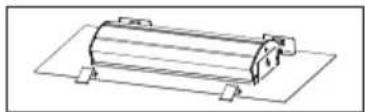
natural_image
Technical line drawing of a cylindrical mechanical component with mounting brackets (no text or symbols)natural_image
Exterior view of a cylindrical industrial lamp or fixture with grid-patterned panel (no visible text or symbols)SOLAMAGIC
natural_image
Isometric line drawing of a mechanical support bracket with mounting holes (no text or symbols)natural_image
Technical line drawing of a cylindrical mechanical component with internal grid structure and mounting bracket (no text or symbols)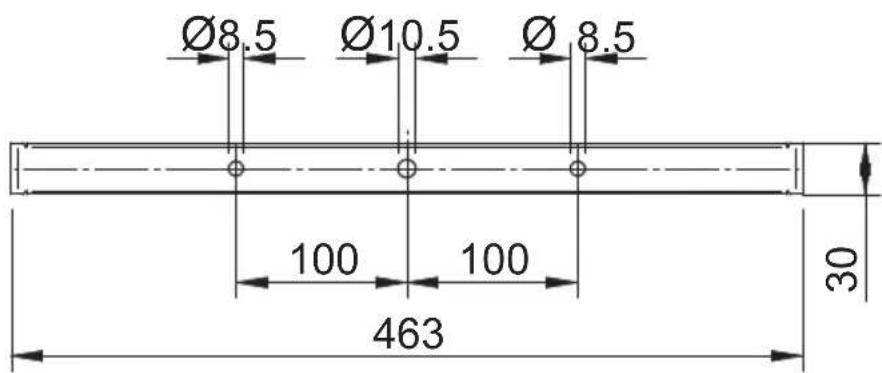
natural_image
Isometric line drawing of a mechanical bracket with mounting holes (no text or symbols)natural_image
Technical line drawings of mechanical components and rods, no text or symbols present
natural_image
Simple line drawing of a mechanical component with a cylindrical shaft and flange (no text or symbols)natural_image
Technical line drawing of a mechanical device with exploded view, showing components like handle, shaft, and housing (no text or labels)natural_image
Exterior view of a cylindrical industrial fan or vent with mesh grille (no text or symbols visible)SOLAMAGIC
natural_image
Isometric line drawing of a metal L-shaped bracket with mounting holes (no text or symbols)natural_image
Technical line drawing of a cylindrical mechanical component with internal grid structure and mounting bracket (no text or symbols)
natural_image
Isometric line drawing of a mechanical bracket with mounting holes (no text or symbols)natural_image
Technical line drawings of mechanical components and rods, no text or symbols present
natural_image
Simple line drawing of a mechanical component with a cylindrical shaft and flange (no text or symbols)natural_image
Technical line drawing of a mechanical device with exploded view, showing components like handle, shaft, and housing (no text or labels)
natural_image
Technical line drawing of a cylindrical mechanical component with mounting brackets (no text or symbols)natural_image
Exterior view of a cylindrical industrial lamp or fixture with grid-patterned panel (no visible text or symbols)SOLAMAGIC
natural_image
Isometric line drawing of a mechanical support bracket (no text or symbols)natural_image
Technical line drawing of a cylindrical mechanical component with internal grid structure and mounting bracket (no text or symbols)
natural_image
Isometric line drawing of a mechanical bracket with mounting holes (no text or symbols)natural_image
Technical line drawings of mechanical components and rods, no text or symbols present
natural_image
Simple line drawing of a mechanical component with a cylindrical shaft and flange (no text or symbols)natural_image
Technical line drawing of a mechanical device with exploded view, showing components like handle, shaft, and housing (no text or labels)
natural_image
Technical line drawing of a cylindrical mechanical component with mounting brackets (no text or symbols)Technical data, safety distances, radiation patterns
Annexes
Zeichen:
Marking:
06/2018


geo
| Layer | Width (m) | Cross Section (m) | | :--- | :--- | :--- | | Top Left | 18 | 2.50 | | Top Right | 27 | 3.50 | | Bottom Left | 42 | 4.75 | | Bottom Right | 74 | 6.00 | | Bottom Center | 1.5 | 2.0 | | Bottom Center | 2.5 | 3.0 | | Bottom Center | 3.0 | — | | Bottom Center | — | — | | Bottom Center | — | CW | LW: 2.50 m x CW: 3.50 m LW: 3.40 m x CW: 4.75 m LW: 4.20 m x CW: 6.00 m LW: 5.00 m x CW: 7.10 m06/2018
SOLAMAGIC 1400 W kompakt
geo
| Layer | Total Water Volume (m³) | |-------|--------------------------| | Top | 85 | | Top | 120 | | Top | 188 | | Top | 335 | | Middle| 2.50 x CW | | Middle| 3.40 x CW | | Middle| 4.20 x CW | | Bottom| 3.0 m | | Bottom| 2.5 m | | Bottom| 2.0 m | | Bottom| 1.5 m | | Bottom| 3.0 m | | Bottom| 4.20 m | | Bottom| 5.00 m | The labels on the bottom are 'LW' and 'CW'. The values for 'LW' are annotated on the top layer.ETHERMA
Elektrowärme GmbH
Landesstraße 16
A-5302 Henndorf
Tel.: +43 (0) 6214 | 76 77
Fax: +43 (0) 6214 | 76 66
Web: www.ethema.com
Mail: office@etherma.com