
AFrame - Multimeter RIDGID - Free user manual and instructions
Find the device manual for free AFrame RIDGID in PDF.

| Product Type | Fault Locator (Ground Leak Detector) with Transmitter FT-103 and Receiver FR-30 |
| Model | RIDGID A-Frame |
| Brand | RIDGID |
| Transmitter Weight | 1 kg (2.2 lb) |
| Transmitter Power Supply | 8 C-type batteries (R14), 12V |
| Receiver Power Supply | 6 AA-type batteries (LR6), 9V |
| Fault Location Frequency | 797 Hz (dFF display) |
| Line Tracing Frequencies | Several predetermined frequencies |
| Transmitter Output Power | Up to 3 watts (adjustable: low, medium, high) |
| Fault Location Range (Depth) | Up to 6 m (20 ft) depending on conditions |
| Fault Location Range (Distance) | Up to 4.8 km (3 mi) depending on conditions |
| Receiver Display | Black and white LCD with directional indication and bar graph |
| Audio Indication | Directional beeps (long/slow for forward, fast for backward) |
| Operating Temperature | -20°C to 55°C (-4°F to 133°F) |
| Storage Temperature | -25°C to 60°C (-13°F to 140°F) |
| Battery Life (Transmitter) | Up to 15 hours continuous, 60 hours intermittent (low power, 1000 ohms) |
| Battery Life (Receiver) | Up to 40 hours continuous, 82 hours intermittent |
| Location Methods | Direct connection, induction clamp (optional), inductive transmission |
| Main Functions | Ground leak location (dFF), cable tracing, underground location, multiple fault detection |
| Maintenance | Clean with a soft damp cloth; remove batteries before storage; do not immerse |
| Safety | Do not connect to live lines; turn off before disconnecting; wear PPE |
| Warranty | RIDGID Lifetime Warranty |
| Included Accessories | FT-103 Transmitter, FR-30 Receiver, ground stake, red and black cables (2.3 m), carrying case, batteries, user manual |
Frequently Asked Questions - AFrame RIDGID
User questions about AFrame RIDGID
0 question about this device. Answer the ones you know or ask your own.
Ask a new question about this device
Download the instructions for your Multimeter in PDF format for free! Find your manual AFrame - RIDGID and take your electronic device back in hand. On this page are published all the documents necessary for the use of your device. AFrame by RIDGID.
USER MANUAL AFrame RIDGID
A-Frame Fault Locator
Model FT-103 Transmitter and Model FR-30 Receiver
natural_image
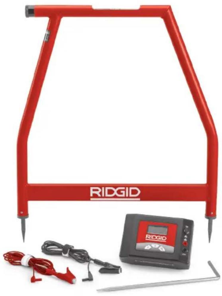
Red RIDGID measurement device with cable and probe components (no visible text or symbols on main subject)Table of Contents
Recording Form for Machine Serial Number 1
Safety Symbols....2
General Safety Rules
Work Area Safety....2
Electrical Safety....2
Personal Safety 2
Equipment Use and Care 2
Service 3
Specific Safety Information
A-Frame Fault Locator Safety 3
RIDGID Contact Information....4
Description....4
Transmitter 4
Receiver 5
Specifications....5
Standard Equipment......6
Changing/Installing Batteries....6
Transmitter 7
Receiver (A-Frame) 7
Pre-Operation Inspection 7
Set-Up And Operation Instructions ....7
Fault Locating
Connecting Transmitter 8
Locating....9
Locating Below Paved Surfaces 10
Multiple Faults....11
Path Locating
Direct Connect Path Locating Method 11
Inductive Clamp Path Locating 12
Broadcast Inductive Path Locating 12
Storage 13
Maintenance
Cleaning 13
Calibration 13
Service And Repair....13
Optional Equipment 14
Disposal 14
Battery Disposal 14
EC Declaration of Conformity....14
FCC Statement....14
Electromagnetic Compatibility (EMC) 14
Lifetime Warranty ....Back Cover
*Original Instructions - English
A-Frame Fault Locator
Model FT-103 Transmitter and Model FR-30 Receiver

natural_image
RidGID-based medical or testing device setup with metal frame, digital display, and cable connectors (no visible text or symbols on main components)
WARNING!
Read this Operator's Manual carefully before using this tool. Failure to understand and follow the contents of this manual may result in electrical shock, fire and/or serious personal injury.
| A-Frame Fault Locator | |
| Record Serial Number below and retain product serial number which is located on nameplate. | |
| Serial No. | |
Safety Symbols
In this operator's manual and on the product, safety symbols and signal words are used to communicate important safety information. This section is provided to improve understanding of these signal words and symbols.

This is the safety alert symbol. It is used to alert you to potential personal injury hazards. Obey all safety messages that follow this symbol to avoid possible injury or death.

DANGER indicates a hazardous situation which, if not avoided, will result in death or serious injury.

WARNING indicates a hazardous situation which, if not avoided, could result in death or serious injury.

CAUTION indicates a hazardous situation which, if not avoided, could result in minor or moderate injury.
NOTICE
NOTICE indicates information that relates to the protection of property.

This symbol means read the operator's manual carefully before using the equipment. The operator's manual contains important information on the safe and proper operation of the equipment.

This symbol means always wear safety glasses with side shields or goggles when handling or using this equipment to reduce the risk of eye injury.

This symbol indicates the risk of electrical shock.
General Safety Rules
WARNING
Read all safety warnings and instructions. Failure to follow the warnings and instructions may result in electric shock, fire and/or serious injury.
SAVE ALL WARNINGS AND INSTRUCTIONS FOR FUTURE REFERENCE!
Work Area Safety
- Keep your work area clean and well lit. Cluttered or dark areas invite accidents.
- Do not operate equipment in explosive atmospheres, such as in the presence of flammable liquids, gases or dust. E equipment can create sparks which may ignite the dust or fumes.
- Keep children and by-standers a way while operating equipment. Distrac tions can cause you to lose control.
Electrical Safety
- Avoid body contact with earthed or ground ed surfaces such as pipes, radiators, ranges and refrigerators. There is an increased risk of electrical shock if your body is earthed or grounded.
- Do not expose equipment to rain or wet
conditions. Water en tering equipment will increase the risk of electrical shock.
Personal Safety
- Stay alert, watch what you are doing and use common sense when operating equipment. Do not use equipment while you are tired or under the influence of drugs, alcohol or medication. A moment of inattention while operating equipment may result in serious personal injury.
- Use personal protective equipment. AI - ways wear eye protection. Protective equipment such as dust mask, non-skid safety shoes, hard hat or hearing protection used for appropriate conditions will reduce personal injuries.
- Do not overreach. Keep proper footing and balance at all times. This enables better control of the power tool in unexpected situations.
- Do not let familiarity gained from frequent use of tools allow you to become complacent and ignore tool safety principles. A careless action can cause severe injury within a fraction of a second.
Equipment Use and Care
- Do not force equipment. Use the correct equipment for your application. The cor-
rect equipment will do the job better and safer at the rate for which it is designed.
- Do not use equipment if the switch does not turn it ON and OFF. Any tool that cannot be controlled with the switch is dangerous and must be repaired.
- Remove the battery pack from the equipment before making any adjustments, changing accessories, or storing. Such preventive safety measures reduce the risk of injury.
- Store idle equipment out of the reach of children and do not allow persons unfamiliar with the equipment or these instructions to operate the equipment. Equipment can be dangerous in the hands of untrained users.
- Maintain equipment. Check for missing parts, breakage of parts and any other condition that may affect the equipment's operation. If damaged, have the equipment repaired before use. Many accidents are caused by poorly maintained equipment.
- Use the equipment and accessories in accordance with these instructions, taking into account the working conditions and the work to be performed. Use of the equipment for operations different from those intended could result in a hazardous situation.
- Keep handles and grasping surfaces dry, clean and free from oil and grease. Slippery handles and grasping surfaces do not allow for safe handling and control of the tool in unexpected situations.
Service
- Have your equipment serviced by a qual - i fied repair person using on ly identical replacement parts. This will ensure that the safety of the tool is maintained.
Specific Safety Information
WARNING
This section contains important safety information that is specific to this tool.
Read these precautions carefully before using the RIDGIDA-Frame Fault Locator to reduce the risk of electrical shock or serious personal injury.
SAVE ALL WARNINGS AND INSTRUCTIONS FOR FUTURE REFERENCE!
Keep this manual with the tool for use by the operator.
A-Frame Fault Locator Safety
- Do not expose the equipment to water or rain. This increases the risk of electrical shock.
- Do not operate the transmitter if operator or transmitter is standing in water. Operating transmitter while in water increases the risk of electrical shock.
- Do not connect to live voltage or active utility lines. Disconnect the conductor to be tested from any other service, components, or anything that might be affected by high voltage. De-energize any circuits in or around the work area.
- Always attach transmitter test leads before turning unit ON and turn unit OFF before disconnecting leads. This will reduce the risk of electrical shock.
- Never turn transmitter ON when anyone is touching the conductor, ground stake, or any part of the transmitter. Turn OFF transmitter before touching test lead or any un-insulated conductor.
- Do not use where a danger of high voltage contact is present. Do not attach leads to high voltage conductors. The equipment is not designed to provide high voltage protection and isolation.
- Locating equipment uses electromagnetic fields that can be distorted and interfered with. More than one utility may be present in a given area. Follow local guidelines and one call/call before you dig service procedures. Exposing a utility is the only way to verify its existence, location and depth.
- Avoid traffic. Pay close attention to moving vehicles when using on or near roadways. Wear visible clothing or reflector vests.
Before operating the RIDGID A-Frame Fault Locator, read and understand this operator's manual and the instructions for any other equipment used. Failure to follow all instructions and warnings may result in property damage and/or serious injury.
- Use this manual in conjunction with all company, utility or facility procedures and policies. Familiarize yourself with all required procedures and policies, including safety practices, prior to entering an area and using the equipment.
NOTICE Ridge Tool Company, its affiliates and suppliers, will not be liable for any injury or any direct, indirect, incidental or consequential damages sustained or incurred by reason of the use of the A-Frame Fault Locator.
RIDGID Contact Information
If you have any question concerning this RIDGID® product:
- Contact your local RIDGID distributor.
- Visit RIDGID.com to find your local RIDGID contact point.
- Contact Ridge Tool Technical Service Department at rtctechservices@emerson.com, or in the U.S. and Canada call (800) 519-3456.
Description
The RIDGID A-Frame Fault Locator is a highly sensitive transmitter and receiver specifically designed to detect the location of a path to ground fault (Direct Fault Finding (DFF)) in the insulation of a buried conductor (such as a wire or cable). Damaged insulation, severed conductor, and other faults with ground leakage are easily and precisely located.
Model FT-103 Transmitter connects to the insulated conductor and establishes a current flow the current leaks to ground through the insulation fault and back to the ground stake. Model FR-30 Receiver detects the current flow to ground through the insulation fault. The receiver provides audio and visual indications of both signal strength and direction to assist in detecting and locating the fault. For the A-Frame fault detector to work, the conductor must be in contact with the earth – it will not work with conductors in conduit.
Additionally, the transmitter can be used to apply a signal to the conductor for path locating with other receivers, such as RIDGID SeekTech or NaviTrackLocators. This can be done by direct connect and inductive methods. Multiple frequencies and power levels are provided.
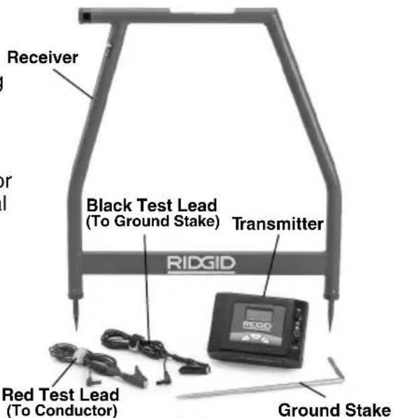
Figure 1 – A-Frame Fault Locator
Transmitter
Transmitter Controls:
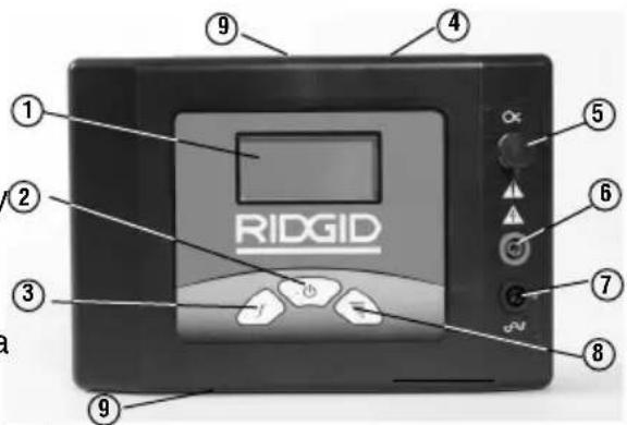
| # | Icon | Description |
| 1. | — | LCD Screen |
| 2. | ON/OFF and Inductive Mode SwitchMain Power Switch – Short press turns unit ON/OFFLong press (5 seconds) enables Broadcast Inductive mode. | |
| 3. | f | Frequency SelectionSelects the frequency of transmitter from preloaded frequencies. See Specifications for frequencies |
| 4. | — | Serial and Warning Label (back of unit) |
| 5. | O × | Inductive Clamp Jack |
| 6. | — | Positive Terminal (to Conductor) |
| 7. | 12 | Negative Terminal (to Ground Stake) |
| 8. | Signal Power SettingDepressing the Signal Power Button cycles the SignalPower between Low, Medium and High | |
| 9. | — | Broadcast Inductive Decal (top and bottom) |
Figure 2 – Transmitter Controls
Transmitter Display:
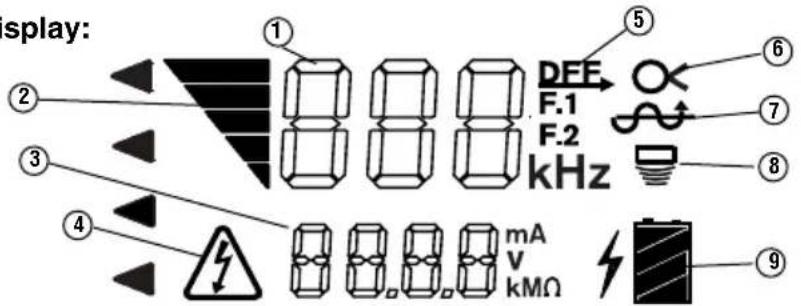
| Number | Icons | Description |
| 1 | - | - kHz Frequency. “dFF” shown for fault finding. |
| 2 | Signal Power  | Bars On Increases with Increasing Power. Three Levels – Low, Medium and High. |
| 3 | - - - | Circuit Information, mA, V or Resistance in Ohms. Transmitter cycles through each at 2 second intervals. |
| 4 | Voltage V  | Transmitter connected to energized conductor – risk of electrical shock.Do not touch transmitter, leads or connections. Use high voltage precautions to disconnect. |
| 5 | Transmitter Set for Fault Finding (dFF displayed in Frequency area (1)). | |
| 6 | Transmit  for Inductive Clamp Use for Path Locating (Insert Inductive clamp into Jack) for Inductive Clamp Use for Path Locating (Insert Inductive clamp into Jack) | |
| 7 | Transmitter Set for Direct Connect Use for Fault Finding or Path Locating. | |
| 8 | Transmitter Set for Broadcast Inductive Mode for Path Locating. | |
| 9 | Transmit  tery Status. tery Status. | |
Figure 3 – Transmitter Display
Receiver
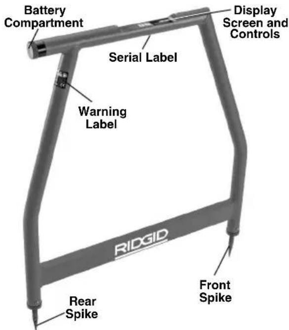
Figure 4 – A Frame Receiver
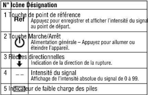
Receiver Controls/Display:
| # | Icon Description |
| 1 | Preference ButtonStores and displays starting signal strength when pressed |
| 2 | ON/OFF ButtonMain Power Switch – Press to turn unit ON/OFF |
| 3 | Directional ArrowIndicates direction of fault |
| 4 | -- Signal StrengthDisplays absolute signal Strength from 0 to 99. |
| 5 | Low Battery Indicator |
Figure 5 – Receiver Controls
Specifications
FT-103 Transmitter:
Operating
Frequencies .....Direct Fault Finding: 797 Hz - "dFF" displayed
Path locating: 128 Hz, 1 kHz, 8 kHz, 33 kHz, 93 kHz Direct Connect: 128 Hz, 1 kHz, 8 kHz, 33 kHz, 93 kHz Inductive Clamp: 8 kHz, 33 kHz, 93 kHz Broadcast Inductive: 33 kHz, 93 kHz
Load Range .....5 Ω to 2M Ω Output Power .....Up to 3 Watts (Low, medium and high settings)
Output Voltage ...5 Volts - 600 Volts Power Supply .....8 × C (R14) Cell Batteries, 12 Volt
Battery Life......Continuous: up to 15 hours, Intermittent: up to 60 hours (on low at 1000 Ohm load)
Operating Temperature ......-4°F to 133°F (-20°C to 55°C)
Storage Temperature......-13°F to 140°F (-25°C to 60°C)
IP Rating ....IP54 Size....8.5" x 5.8" x 2.5" (21 cm x 15 cm x 6 cm)
Weight.....2.2 lbs. (1 kg) Test Lead Jacks.....0.16" (4mm) a IEC61010
FR-30 A-Frame Receiver:
Operating Frequencies ......Fault Finding: 797 Hz - "dFF" displayed Direct Connect:
Fault Finding Depth ....Up to 20' (6m) (depending on conditions)
Fault Finding Length.....Up to 3 miles (4800 m) (depending on conditions)
Display ....Black and White LCD Audio Indication ....Piezo Response
Power Supply.....6 × AA (LR6) Batteries, 9 Volt
Battery Life......Continuous: up to 40 hours, Intermittent: up to 82 hours
Operating Temperature .....-4°F to 133°F (-20°C to 55°C)
Storage Temperature......-13°F to 140°F (-25°C to 60°C)
IP Rating ....IP54 Size....30.3" x 30.4" x 1.5" (77 cm x 77 cm x 4 cm)
Weight......3 lbs. (1.3 kg)
Standard Equipment
The A-Frame Fault Locator package includes the following items:
• FR-30 A-Frame Receiver
• FT-103 Transmitter
- Ground Stake
- Red and Black Test Leads (7.5' (2.3 m) long)
- Carry Cases
- Batteries
- Operator's Manual Pack
NOTICE This equipment is used for conductor fault and path locating. Incorrect use or improper application may result in incorrect or inaccurate locating. Selection of appropriate locating methods for the conditions and proper operation is the responsibility of the user.
Changing/Installing Batteries
WARNING
Switch unit OFF and remove any connections from the Transmitter/Receiver before changing batteries.
The A-Frame Fault Locator is supplied without the batteries installed. Remove the batteries prior to storage to avoid battery leakage. When the low battery indicator appears on the transmitter (☐) or receiver (☐) display, the batteries need to be replaced.
NOTICE Use the batteries that are of same type. Do not mix battery types. Do not mix new and used batteries. Mixing batteries can cause overheating and battery damage.
Transmitter:
- With device OFF, remove the battery compartment cover. If needed, remove batteries (Figure 6).
Fault Locator and correct any problems to reduce the risk of serious injury from electric shock and other causes, and prevent equipment damage.
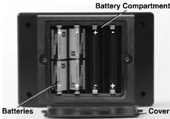
Figure 6 – Changing the Batteries (Transmitter)
- Install eight new C Cell alkaline batteries (R14), observing correct polarity as indicated in the battery compartment.
- Securely reinstall the battery compartment cover.
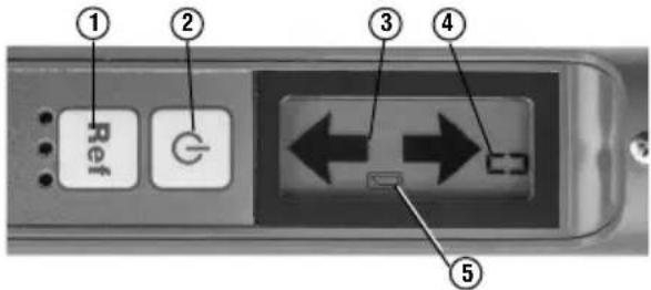
Receiver (A-Frame):
- With device OFF, unscrew the battery com partment cover on the top tube (Figure 7). If needed, remove batteries.
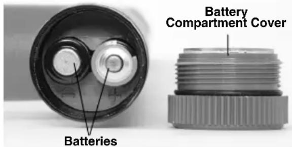
Figure 7 – Changing the Batteries (Receiver)
- Install six new AA alkaline batteries (LR6), observing correct polarity as indicated in the battery compartment.
- Securely reinstall the battery compartment cover.
Pre-Operation Inspection
WARNING
Daily before use, inspect your A-Frame
- Make sure the transmitter and receiver units are OFF.
- Remove the batteries and inspect for signs of damage. Replace if necessary. Do not use if the batteries are damaged.
- Clean the equipment. This aids inspection and helps prevent the tool from slipping from your grip.
-
Inspect the locator for the following:
-
Proper assembly, maintenance and completeness.
- Any broken, worn or missing parts.
- Inspect the transmitter test leads for damaged insulation or exposed wire.
- Presence and readability of the transmitter and receiver warning labels (Figure 2 and 4).
- Any other condition which may prevent safe and normal operation.
If any problems are found, do not use the A-Frame Fault Locator until the problems have been repaired.
- Inspect and maintain any other equipment being used per its instructions to make sure it is functioning properly.
Set-Up And Operation Instructions
WARNING

Do not connect to live voltage or active utility lines. Disconnect the conductor to be tested from any other service, components, or anything that might be affected by high voltage. De-energize any circuits in or around the work area.
Always attach transmitter test leads before turning unit ON and turn unit OFF before disconnecting leads. This will reduce the risk of electrical shock.
Never turn transmitter ON the unit when anyone is touching the conductor, ground stake, or any part of the transmitter. Turn
OFF transmitter before touching test lead or any un-insulated conductor.
Do not use where a danger of high voltage contact is present. Do not attack leads to high voltage conductors. The equipment is not designed to provide high voltage protection and isolation.
Locating equipment uses electromagnetic fields that can be distorted and in-
terfered with. More than one utility may be present in a given area. Follow local guidelines and one call/call before you d service procedures. Exposing a utility is the only way to verify its existence, location and depth.
Follow set up and operating instructions to reduce the risk of injury from electrical shock and other causes and to prevent tool damage
Model FT-103 Transmitter and Model FR-30 Receiver are used for fault locating of conductors through direct connect method.
The Model FT-103 Transmitter only can be used for path locating with RIDGID SeekTech and NaviTrack® Locators. This can be done by direct connect and inductive methods.
- Confirm have appropriate work area (See General Safety Rules). Operate in clear, level, stable, dry location. Do not use transmitter while standing in water.
- Determine the correct equipment for the application, see Description and Specifications sections.
- Make sure all equipment has been inspected and set up as directed in their instructions.
Fault Locating
It is good practice to locate the conductor path before attempting to fault locate. This can be done using a variety of RIDGID locating equipment. If during the location of the conductor path an unusual amount of signal loss occurs, this may give some indication of the conductor insulation fault location. Additionally, use visual cues and past history to aid in identifying the conductor path and potential fault locations. Once the conductor path is determined, the RIDGID FT-103 Transmitter and FR-30 A-Frame Receiver can be used to locate ground faults in the insulated conductor. The Model FT-103 Transmitter connects to the insulated conductor and establishes a current flow, the current leaks to ground through the insulation fault
and back to the ground stake. The Model FR-30
Receiver detects the current flow to ground through the insulation fault. For the A-Frame Fault detector to work, the conductor must be in contact with the earth – it will not work with conductors in conduit. Generally, the A-Frame Fault Locator works best in earth. Use with gravel, asphalt, concrete or other ground covers may not work as well.
The signal strength at the fault depends on the amount of current leaking there. The greater the leakage, the greater the signal strength.
Connecting Transmitter
-
Disconnect all loads and grounds from the conductor to be tested and all neighboring conductors to prevent damage from high voltage and false reading. Both ends should be known and disconnected. Disconnecting both ends of the conductor forces all of the transmitter signal through the fault, improving the fault locate.
-
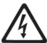
Insert supplied ground stake into the earth. Ideally, the ground stake should be in line with the conductor, 3' to 6' (1m to 2m) from the end. If conditions require, the ground stake can be placed to the side of the conductor. Do not to place the ground stake over the conductor. It is not recommended to use other existing grounds, existing grounds may result in signal being inadvertently applied to non-target cables.
A good ground results in a stronger tracing signal. To get a good ground, insert the ground stake as far as possible into the earth. Moist earth will give a better ground than dry earth. Wetting the earth around the ground stake can improve grounding. This lowers the resistance of the circuit. While moist earth around the ground stake improves the circuit, do not use the transmitter in areas that are wet, this can increase the risk of electrical shock.
-
Make sure that the transmitter is OFF.
-
Connect BLACK test lead to the ground stake. Always connect to the ground stake first.
-
Connect the BLACK and RED test leads to the Transmitter.
Connect the RED test lead to the conductor to be tested (see Figure 9).
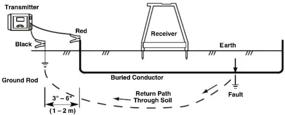
Figure 8 – Transmitter Connections for Fault Locating
Locating
- Make sure that no one is near or touching the conductor, transmitter, leads or ground stake. Press the ON/OFF button on the transmitter to turn the transmitter ON. When the transmitter is turned on, it is set to the last used frequency. If needed, press the frequency button on the transmitter until "dFF" is shown on screen (Figure 9).
Figure 9 – Transmitter Screen
THE TRANSMITTER, LEADS OR CONNECTIONS. The target conductor is energized and there is the risk of electrical shock. Use high voltage precautions to disconnect.
- When fault locating, generally the receiver should be used over the conductor, with the front receiver spike towards the expected fault and the rear receiver spike towards the ground stake. The receiver spikes should evenly penetrate the earth to make good electrical contact. The current flowing in and out of the ground spikes supplies the signal to locate the insulation fault (see Figure 10).
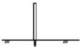
natural_image
Simple line drawing of a vertical line intersecting a horizontal line with two small hatched markers at the bottom (no text or symbols)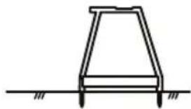
natural_image
Simple line drawing of a trapezoidal structure with two supports at the base (no text or symbols)Adjust the signal power by pressing the signalFigure 10 – Receiver Positioning power button to cycle through the settings (low, medium and high). Using high power may result in signal going to ground at non-target points, low power may mean a circuit is not created. The transmitter will display circuit resistance (OHMS) at the bottom of the LCD. The lower the resistance the better the locate signal. To improve the circuit, improve the ground, check the lead connections or increase the power.
The transmitter will continuously beep when there is a circuit. The lower the circuit resistance, the quicker the beep. The transmitter will beep three times and a pause (repeating) if there is no circuit.
If the transmitter display shows voltage warning (Figure 3), the transmitter is connected to live voltage. If this happens, DO NOT TOUCH
- To start the locate, place the A-Frame receiver between the ground stake and the transmitter connection to the conductor. Press the A-Frame Receiver ON/OFF button to turn receiver ON.
The signal strength will appear on the receiver display. Signal strength will be the highest near the ground stake and at faults. Press the "Ref" button to store a reference signal strength near the ground stake.
The receiver display arrows will indicate the direction of the fault. Fault direction is also indicated audibly - a long slow beep indicates forward direction and a quick beep indicates backward direction.
- Remove the receiver from the earth and move several steps as indicated by the directional arrow and beeping along the conductor path. Reinsert the receiver spikes into the earth (Figure 11).
Continue moving away from the ground stake along the conductor path. Signal strength should drop (in some cases going to zero) and then rise as you move towards a fault.
- Signal strength will peak over the fault. If you pass the fault, the directional arrow will change direction and the beep will change 6. from long slow to quick beep and the signal strength will decrease. Continue to move the receiver back and forth until slight movement causes the directional arrows and beeping to toggle back and forth. At this point, the fault is centered between the spikes of the receiver.
Compare the signal strength to the reference signal strength taken near the ground stake. They should be similar. If the fault signal strength is much lower than t reference value, you may not have lo- cated a fault. For instance, a grounded splice point would behave as a fault during the locate, but would give a much lower signal strength. For a low fault signal strength, you may want to mark the location and continue down the conductor locating can be difficult if the fault is below a paved surface, because the receiver spikes cannot make good electrical contact with the earth. In this case, there are several methods that can be used.
path looking for a fault signal strength closer to the reference signal.
Once a fault is located with a signal similar to the reference signal, turn the A-Frame Locator perpendicular to the path of the conductor. Move the receiver back and forth until slight movement causes the directional arrows and beeping to toggle back and forth. At this point, the fault is centered between the spikes of the receiver. See Figure 12. Mark the location of the fault.
Once the locating is completed, press the ON/OFF button to turn the transmitter OFF. Always turn the unit OFF before disconnecting the cable leads to reduce the risk of electrical shock. Remove the cable lead from the target conductor first. Always disconnect the cable lead from the target conductor first before removing the cable lead from the ground spike to reduce the risk of electrical shock. Disconnect the cable lead from the ground spike.
^16 Locating Below Paved Surfaces
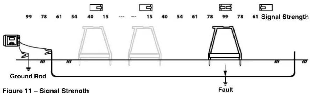
Figure 11 – Signal Strength
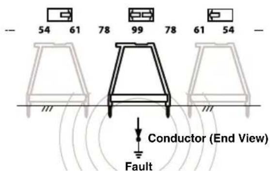
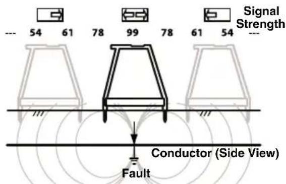
Figure 12 – Final Locate
- If the paved area is relatively small, the can be used to apply an active tracing signal to receiver can be used around the peripherya conductor in three ways:
of the area. The receiver can be rotated side to side, and where the receiver directional arrows and beeping toggle back and forth, extend a straight line perpendicular to the center of the A-Frame Receiver. Do this in several locations around the suspected fault area. The straight lines should all intersect at the same point. This is the location of the fault. This method of locating is less exact than placing the receiver directly over the conductor. See Figure 13.
- An alternate way to locate below paved surfaces is to improve the conductivity between the pavement and the receiver with water. One method is to attach sponges to the spikes of the receiver. Wet the sponges with water and keep wet. Conduct the fault locate normally.
- Another method is to wet the surface of the pavement with water and conduct the fault locate normally. Do not do this in the area of the transmitter – this increases the risk of electrical shock.
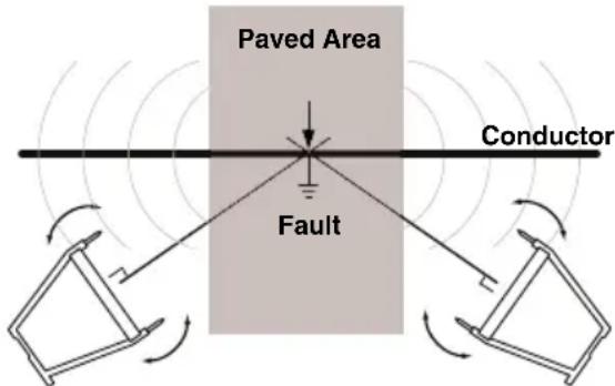
Figure 13 – Locating below paved surfaces
Multiple Faults
If there are multiple faults in the conductor, the faults will have signals proportional to the amount of current leaking. The locate is done the same as for a single fault, but the signal strength will not be as strong. Typically, the largest fault (least resistance fault) is easiest to find. Best practice is to find and repair the first fault and continue the locate for other faults.
Path Locating
The FT-103 Transmitter can be used with other commercially available receivers (such as the RIDGID SeekTech or NaviTrack receivers) to 4 path locate conductors. The FT-103 transmitter
- Direct Connect – The transmitter's leads are connected directly to the target conductor and a suitable ground. This method is most commonly used when the target utility is accessible. Direct connect should not be used for energized (live) conductors.
- Inductive Clamp (optional equipment) – the jaws of the inductive clamp encircle the target conductor; if the conductor is insulated, there is no metal to metal contact. This method is commonly used when the target utility is accessible but direct connect is not possible on an insulated cable.
- Broadcast Inductive Mode – The transmitter generates a field, which in turn induces a current in the target conductor. There is no direct connection between the transmitter and the target conductor. The transmitter is placed over and inline with the target conductor. The transmitter's internal antenna induces a signal onto the target conductor. This method is most commonly used when the target utility is not accessible.
Disconnect all loads from the conductor to be tested and all neighboring conductors to prevent damage from high voltage and false reading.
Direct Connect Path Locating Method
- Insert supplied ground stake into the earth. Or, if other good grounds are available in the area, they can be used.
A good ground results in a stronger tracing signal. To get a good ground, insert the ground stake as far as possible into the earth. Moist earth will give a better ground than dry earth. Wetting the earth around the ground stake can improve grounding. This lowers the resistance of the circuit. While moist earth around the ground stake improves the circuit, do not use the transmitter in areas that are wet, this can increase the risk of electrical shock.
The far end of the conductor should be grounded.
- Make sure that the transmitter is OFF.
- Connect BLACK test lead to the ground stake. Always connect to the ground stake first.
-
Connect the BLACK and RED test leads to the Transmitter.
-
Connect the RED test lead to the conductor to be tested.
-
Press the ON/OFF button to turn the transmitter ON. When the transmitter is turned on, it is set to the last used frequency. Press the frequency selection button to cycle through frequency settings to the desired locating frequency.
Adjust the signal power by pressing the signal power button to cycle through the settings (low, medium and high). Using high power can couple into non-target conductors, low power may mean a circuit is not created. The transmitter will display circuit resistance (OHMS) at the bottom of the LCD. The lower the resistance the better the locate signal. To improve the circuit, improve the ground, check the lead connections, increase power or change the frequency.
If the transmitter display shows voltage warning (Figure 3), the transmitter is connected to live voltage. If this happens, DO NOT TOUCH THE TRANSMITTER, LEADS OR CONNECTIONS. The target conductor is energized and there is the risk of electrical shock. Use high voltage precautions to disconnect.
-
Check the circuit and adjust signal power, grounding or connections to ensure locatable field.
-
Turn ON the receiver/locator and follow the instructions for the receiver. Make sure the receiver's frequency is set to match that on the transmitter. Confirm the receiver is picking up the transmitted frequency by holding it near the transmitter and observing the increase in receiver signal.
-
Once the locating is completed, press the ON/OFF button to turn the transmitter OFF. Always turn the unit OFF before disconnecting the cable leads to reduce the risk of electrical shock. Remove the cable lead from the target conductor first. Always disconnect the cable lead from the target conductor first before removing the cable lead from the ground spike to reduce the risk of electrical shock. Disconnect the cable lead from the ground spike.
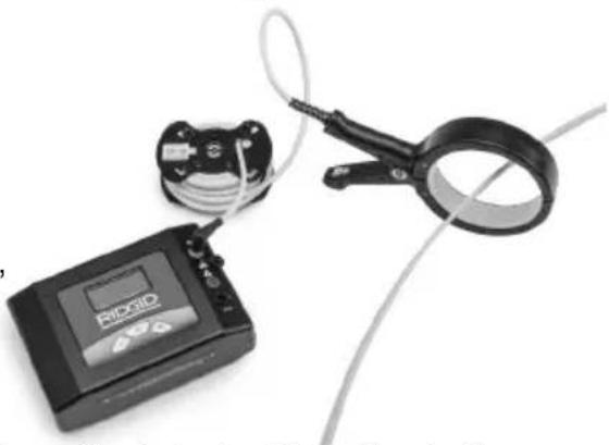
Inductive Clamp Path Locating
- This method requires an inductive clamp (Optional equipment). Read and follow
all instruction for the use of the inductive clamp.
-
Insert the plug of the inductive clamp into transmitter (see Figure 2).
-
Clamp the jaws of the inductive clamp around the target conductor. Make sure that the jaws of the clamp are fully closed. (See Figure 14). Both ends of the conductor should be grounded for best results.
natural_image
Medical device with attached cable and clamp, no visible text or symbolsFigure 14 – Inductive Clamp Attached to a Conductor
- Press the ON/OFF button to turn the transmitter ON. When the clamp is plugged in the clamp symbol ( × ) shows on the screen and only clamp frequencies are available. Press the frequency selection button to cycle through frequency settings to the desired locating frequency. Adjust the signal power by pressing the signal power button to cycle through the settings (low, medium and high). The inductive clamp typically works best with frequencies around 8kHz, 33 kHz, 93kHz.
- Check the circuit and adjust signal strength (see Figure 3, Circuit Information).
- Turn ON the receiver/locator and follow the instructions for the receiver. Make sure the receiver's frequency is set to match that on the transmitter. Confirm the receiver is picking up the transmitted frequency by holding it near the transmitter and observing the increase in receiver signal.
- Once the locating is completed, press the ON/OFF button to turn the transmitter OFF.
Broadcast Inductive Path Locating
- Properly place the transmitter relative to the target conductor (see Figure 15). On the top of the transmitter is an arrow. Set
transmitter on ground, align arrow with the target conductor.
- Press the ON/OFF button to turn the trans mitter ON. Press and hold the power button for 5 seconds selection button to shift transmitter into broadcast inductive mode. Broadcast inductive icon ☐) appears on screen and the transmitter will start beeping to indicate that it is operating.
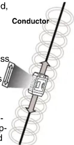
Figure 15 – Orientation to the Line – Inductive Mode
Adjust the signal power by pressing the signal power button to cycle through the settings (low, medium and high) and choose high. Press the frequency selection button to cycle through 33kHz and 93kHz frequency settings to the desired locating frequency. When using Broadca Inductive Mode, higher frequencies tend to get a better signal at the receiver.
- Turn ON the locator and follow its instructions. Make sure to set the receiver to the same frequency as the transmitter.
ductor. This is called "Air Coup ling". Operate the receiver at least 30 feet from the transmitter to prevent this. (See Figure 16).
One way to confirm that you are tracing the target conductor and not the transmitter field is to look for a strong, stable prox imity signal and a valid depth measurement on the receiver. While directly over the energized line you can also raise the receiver a set distance off of the ground, and verify that the depth reading on the display e - equals the distance that you raised the receiver.
- Once the locating is completed, press the Power ON/OFF button for 5 seconds to exit broadcast inductive mode, then press the ON/OFF button to turn the transmitter OFF.
Storage
Remove batteries from tool. Store the A-Frame Fault Locator in case. Avoid storing in extreme heat or cold.
⚠ WARNING Store tool in a dry, secured area that is out of reach of children and people unfamiliar with the RIDGID A-Frame Fault Locator. The locator is dangerous in the hands of untrained users.
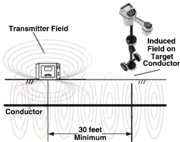
Figure 16 – Orientation to the Line – Inductive Mode
Maintenance
WARNING
Remove batteries from tool before performing maintenance or making any adjustment.
Cleaning
Do not immerse the A-Frame Fault Locator in water. Wipe off dirt with a damp soft cloth. Avoid rubbing too hard. Do not use aggressive cleaning agents or solutions.
Calibration
The A-Frame Fault Locator is factory calibrated and only requires recalibration if repaired.
Service And Repair
WARNING
Improper service or repair can make the machine unsafe to operate.
Service and repair on this A-Frame Fault Lo -
When the transmitter is in broadcast induc tive mode, it generates a field around the transmitter. This field is in both the ground (towards the target conductor) and into the air around the transmitter. When the receiver is within approximately 30 feet (10 meters) of the transmitter, it will measure the field directly from the transmitter and not the signal induced on the target con-
cator must be performed by a RIDGID Inde-pendent Service Center. Use only RIDGID service parts.
For information on your nearest RIDGID Inde - pen dent Service Center or any service or repair questions, see Contact Information Section in this manual.
Optional Equipment
WARNING
To reduce the risk of injury, only use accessories specifically designed and rec-FCC Statement
ommended for use with the RIDGID A-This equipment has been found to comply Frame Fault Locator, such as listed below with the limits for a Class B digital device, For a complete listing of RIDGID equipment available for this tool, see the Ridge Tool Catalog online at RIDGID.com or see Contact Information.
| CatalogNo. Description | |
| 20973 R | DGID SeekTech 4" (100 mm)Inductive Signal Clamp |
| 57763 G | Ground Stake, FT-103 |
| 57768 R | Red and Black Test Leads, FT-103 |
| 96967 R | DGID NaviTrack II Locator |
| 19238 R | DGID NaviTrack Scout Locator |
| 22163 R | DGID SeekTech SR-60 Line Locator |
| 21893 R | DGID SeekTech SR-20 Line Locator |
| 44473 R | DGID SR-24 Line Locator withBluetooth®and GPS |
Disposal
Parts of this tool contain valuable materials and can be recycled. There are companies that specialize in recycling that may be found locally. Dispose of the components in compliance with all applicable regulations. Contact your local waste management authority for more information.
For EC Countries: Do not dispose of elec trical equipment with house-hold waste!
According to the European Guide - line 2012/ 19/EU for Waste Elec tric and Electronic Equipment and its
imple men tation into national legislation, elec trical equipment that is no longer usable must be collected separately and disposed of in an environmentally correct manner.
Battery Disposal
For EC countries: Batteries must be recycled according to the guideline 2006/66/EEC.
EC Declaration of Conformity
The EC Declaration of Conformity (890-011-320.10) will accompany this manual as a separate booklet when required.
FCC Statement
-This equipment has been found to comply with the limits for a Class B digital device, pursuant to part 15 of the FCC Rules. These limits are designed to provide reasonable protection against harmful interference in a residential installation.
This equipment generates, uses, and can radiate radio frequency energy and, if not installed and used in accordance with the instructions, may cause harmful interference to radio communications.
However, there is no guarantee that interference will not occur in a particular installation.
If this equipment does cause harmful interference to radio or television reception, which can be determined by turning the equipment OFF and ON, the user is encouraged to try to correct the interference by one or more of the following measures:
- Reorient or relocate the receiving antenna.
- Increase the separation between the equipment and receiver.
- Consult the dealer or an experienced radio/ - TV technician for help.
Electromagnetic Compatibility (EMC)
The term electromagnetic compatibility is taken to mean the capability of the product to function smoothly in an environment where electromagnetic radiation and electrostatic discharges are present and without causing electromagnet interference to other equipment.
NOTICE The RIDGID A-Frame Fault Locator conform to all applicable EMC standards. However, the possibility of it causing interference in other devices cannot be precluded. All EMC related standards that have been tested are called out in the tool's technical document.
natural_image
RidGID-based medical or testing device setup with metal frame, digital display, and cable connectors (no visible text or symbols on main components)
AVERTISSEMENT
 |
128 Hz, 1 kHz, 8 kHz, 33
kHz, 93 kHz
Connexion directe :
128 Hz, 1 kHz, 8 kHz, 33
kHz, 93 kHz
Pince à induction :
8 kHz, 33 kHz, 93 kHz
Transmission inductive :
33 kHz, 93 kHz
Protection IP.....IP54
Dimensions .....8,5" x 5,8" x 2,5"
(21 cm x 15 cm x 6 cm)
Protection IP.....IP54
Dimensions .....30,3" x 30,4" x 1,5"
(77 cm x 77 cm x 4 cm)
Poids ......3 livres (1,3 kg)
Equipements de base
natural_image
Two black-and-white symbols: a circular icon with a person wearing glasses and a triangular warning sign with a lightning bolt (no text or numbers present)natural_image
Simple line drawing of a vertical object with a downward arrow, resting on a horizontal baseline (no text or symbols)natural_image
Simple line drawing of a trapezoidal structure with two legs and a horizontal base (no text or symbols)natural_image
Medical device with digital display and coiled cable, no visible text or symbolsnatural_image
RidGID-based medical imaging device with attached display and cable, no visible text or symbols on main components
ADVERTENCIA
natural_image
Two black-and-white symbols: a circular icon with a face wearing glasses and a triangular warning sign with a lightning bolt (no text or numbers present)natural_image
Medical device with RIOQIO sensor and coiled cable, no visible text or symbolsFigura 14 – Pinza inductiva conectada a un conductor
RIDGID ^® tools are warranted to be free of defects in workmanship and material.
How long coverage lasts
This warranty lasts for the lifetime of the RIDGID ^™ tool. Warranty coverage ends when the product becomes unusable for reasons other than defects in workmanship or material.
How you can get service
To obtain the benefit of this warranty, deliver via prepaid transportation the complete product to RIDGE TOOL COMPANY, Elyria, Ohio, or any authorized RIDGE INDEPENDENT SERVICE CENTER. Pipe wrenches and other hand tools should be returned to the place of purchase.
What we will do to correct problems
Warranted products will be repaired or replaced, at RIDGE TOOL'S option, and returned at no charge; or, if after three attempts to repair or replace during the warranty period the product is still defective, you can elect to receive a full refund of your purchase price.
What is not covered
Failures due to misuse, abuse or normal wear and tear are not covered by this warranty. RIDGE TOOL shall not be responsible for any incidental or consequential damages.
How local law relates to the warranty
Some states do not allow the exclusion or limitation of incidental or consequential damages, so the above limitation or exclusion may not apply to you. This warranty gives you specific rights, and you may also have other rights, which vary, from state to state, province to province, or country to country.
No other express warranty applies
This FULL LIFETIME WARRANTY is the sole and exclusive warranty for RIDGE products. No employee, agent, dealer, or other person is authorized to alter this warranty or make any other warranty on behalf of the RIDGE TOOL COMPANY.

Parts are available online at RIDGIDParts.com
Ridge Tool Company
400 Clark Street
Elyria, Ohio 44035-6001
U.S.A.
Ce qui est couvert


- A-Frame Fault Locator
- Model FT-103 Transmitter and Model FR-30 Receiver
- Table of Contents
- General Safety Rules
- Specific Safety Information
- Fault Locating
- Path Locating
- Maintenance
- WARNING!
- Safety Symbols
- NOTICE
- WARNING
- SAVE ALL WARNINGS AND INSTRUCTIONS FOR FUTURE REFERENCE!
- Work Area Safety
- Electrical Safety
- Personal Safety
- Equipment Use and Care
- Service
- A-Frame Fault Locator Safety
- RIDGID Contact Information
- Description
- Transmitter
- Specifications
- FT-103 Transmitter:
- FR-30 A-Frame Receiver:
- Standard Equipment
- Changing/Installing Batteries
- Transmitter:
- Fault Locator and correct any problems to reduce the risk of serious injury from electric shock and other causes, and prevent equipment damage.
- Receiver (A-Frame):
- Pre-Operation Inspection
- Set-Up And Operation Instructions
- Connecting Transmitter
- Locating
- Locating Below Paved Surfaces
- Multiple Faults
- Direct Connect Path Locating Method
- Inductive Clamp Path Locating
- Broadcast Inductive Path Locating
- Storage
- Cleaning
- Calibration
- Service And Repair
- Optional Equipment
- To reduce the risk of injury, only use accessories specifically designed and rec-FCC Statement
- Disposal
- Battery Disposal
- EC Declaration of Conformity
- FCC Statement
- Electromagnetic Compatibility (EMC)
- AVERTISSEMENT
- Equipements de base
- ADVERTENCIA
- How long coverage lasts
- How you can get service
- What we will do to correct problems
- What is not covered
- How local law relates to the warranty
- No other express warranty applies
- Parts are available online at RIDGIDParts.com
- Ridge Tool Company
- Ce qui est couvert
Brand : RIDGID
Model : AFrame
Category : Multimeter