T170 - Tumble drier Dexter Laundry - Free user manual and instructions
Find the device manual for free T170 Dexter Laundry in PDF.

| Brand | Dexter Laundry |
| Model | T170 |
| Product Type | Gas Industrial Dryer |
| Load Capacity | 170 lb (77 kg) dry linen |
| Dimensions (H x W x D) | 81 x 53.5 x 63.14 in (206 x 136 x 160 cm) |
| Net Weight | Approximately 1500 lb (680 kg) |
| Drum Volume | 59 ft³ (141.8 L) |
| Drum Diameter | 50.14 in (127.8 cm) |
| Drum Depth | 43.2 in (115.5 cm) |
| Power Type | Natural gas or LPG (models available); electric 208-240 V, 60 Hz |
| Gas Consumption | 400,000 BTU/h (117.2 kW) |
| Gas Connection | 1 in (25.4 mm) NPT |
| Drum Speed | 32.5 rpm (reversing model) |
| Drive Motor | 2 hp (1.5 kW) for reversing; 1 hp (0.75 kW) standard |
| Drying Cycles | Automatic with moisture detection (0 to 25% residual moisture) |
| Drying Temperatures | Cotton 190 °F, Blend 160 °F, Synthetic 140 °F, Wool 140 °F, Delicate 120 °F, Extra Delicate no heat |
| Drum Reversal | Yes (reversing model) |
| Exhaust | Diameter 12 in (30.5 cm), maximum recommended length 14 ft (4.3 m) with 2 elbows |
| Make-up Air | 3 ft² (0.28 m²) net opening required |
| Overheat Detection System | With alarm and automatic shutdown; water extinguishing option |
| Daily Maintenance | Clean lint filter |
| Monthly Maintenance | Check baffles, belts, and burner area |
| Maintenance Parts | Motor belt (9040-076-008), drum belt (9040-082-001), lint filter (9822-034-001) |
| Warranty | Standard manufacturer warranty (see notice) |
| Standards | ANSI Z223.1, CAN/CGA-B149, AS/NZA 5601, NFPA 70 |
Frequently Asked Questions - T170 Dexter Laundry
User questions about T170 Dexter Laundry
0 question about this device. Answer the ones you know or ask your own.
Ask a new question about this device
Download the instructions for your Tumble drier in PDF format for free! Find your manual T170 - Dexter Laundry and take your electronic device back in hand. On this page are published all the documents necessary for the use of your device. T170 by Dexter Laundry.
USER MANUAL T170 Dexter Laundry
The dryer must not be stored or installed where it will be exposed to water and/or weather.
WARNING:
FIRE OR EXPLOSION HAZARD
Failure to follow safety warnings exactly could result in serious injury, death or property damage.
- Do not store or use gasoline or other flammable vapors and liquids in the vicinity of this or any other appliance.
WHAT TO DO IF YOU SMELL GAS
- Do not try to light any appliance.
- Do not touch any electrical switch; do not use any phone in your building.
- Clear the room, building or area of all occupants.
- Immediately call your gas supplier from a neighbor's phone. Follow the gas supplier's instructions.
- If you cannot reach your gas supplier, call the fire department.
- Installation and service must be performed by a qualified installer, service agency or the gas supplier.
Post the following "For Your Safety" caution in a prominent location:
FOR YOUR SAFETY
Do not store or use gasoline or other flammable vapors or liquids in the vicinity of this or any other appliance.
It is important that you read this Manual and retain it for future reference. For service or replacement parts, contact the distributor in your area or the manufacturer.
You, the purchaser, must post in a prominent location instructions to be followed in the event the use smells gas. Consult your local gas supplier for procedure to be followed if the odor of gas is present.
TABLE OF CONTENTS
1s WARNINGS ABOUT USE AND OPERATION 3s
2s DRYER SPECIFICATION SHEET 4s
3s T-30 DRYER DIMENSIONS. 5s
4s T-50 REVERSING DRYER DIMENSIONS 8s
5s T-80 REVERSING AND NON-REVERSING DRYER DIMENSIONS. 11s
6s T-120 REVERSING DRYER DIMENSIONS 14s
7s T-170 REVERSING DRYER DIMENSIONS 17s
8s INSTALLATION INSTRUCTIONS 20s
8.1s UNCRATING 20s
8.2s DRYER INSTALLATION 20s
8.2.1s CODE CONFORMITY 20s
8.2.2s INSTALLATION CLEARANCES 20s
8.2.3s MAKE-UP AIR 21s
8.2.4s ELECTRICAL REQUIREMENTS 21s
8.2.5s IMPORTANT: TRANSIENT VOLTAGE SURGE SUPPRESSORS 21s
8.2.6s GAS REQUIREMENTS 22s
8.2.7s EXHAUST INSTALLATION 23s
8.3s DRYER IGNITION (SOLID STATE IGNITION) 24s
8.4s WATER CONNECTION - OPTIONAL MODEL 25s
8.5s DRYER SHUTDOWN 25s
9s OPERATING INSTRUCTIONS 25s
9.1s STARTING THE DRYER 25s
9.2s END OF CYCLE 26s
10s PROGRAMMING/MANAGEMENTVIEW 26s
10.1s ENTER PROGRAMMING MODE 26s
11s AUTODRY CYCLES 26s
12s OVERHEAT SENSING 26s
135 DRYER ERROR MESSAGES 27s
14sServICING THE DRYER 33s
15s PREVENTIVE MAINTENANCE INSTRUCTIONS 34s
16s INSTRUCTIONS - CONVERT A DUAL VOLTAGE DRYER FROM 120V to 208-240V 35s
1 WARNINGS ABOUT USE AND OPERATION
It is ABSOLUTELY ESSENTIAL that the dryer be grounded to a known earth (zero) ground. This is not only for personal safety, but is necessary for proper operation.
DO NOT MODIFY THIS APPLIANCE. KEEP SHIELDS, GUARDS, AND COVERS IN PLACE. These safety devices are provided to protect everyone from injury.
THIS DRYER IS EQUIPPED WITH AN OVER-TEMPERATURE THERMOSTAT located to the right of the motor on the rear of the cabinet. If the dryer ceases to operate, refer to your "Service Procedure and Parts Data" book for instructions.
CHECK THIS THERMOSTAT WHEN INSTALLING THE DRYER to assure it is not tripped. Impacts such as rough handling in shipment, may trip the thermostat.
DO NOT SPRAY AEROSOLS IN THE VICINITY OF THIS APPLIANCE while in operation.
THIS APPLIANCE SHALL NOT BE USED TO DRY OFF CLOTHES CONTAINING SOLVENTS OR DRY CLEANING FLUIDS.
Additional warning for dryer models with water dispensing systems:

WARNING: ELECTRICAL SHOCK HAZARD
Electrical shock can result in death or serious injury.
If the water dispensing system is activated do not attempt to operate the dryer.
If the water dispensing system is activated have the dryer inspected by a qualified agency before operating the dryer.
2 DRYER SPECIFICATION SHEET
| T-30 | T-50 | T-80 | T-120 | T-170 | ||||||||||||||
| Capacity 80 (13.51) 50 (2) DINOWeight DINO(1) B(1) | Cylinder Volume - cf(1) | 11.3 (320) | 15.8 (67.4) | 23 (65.3) | 3.1 (102.2) | 50 (34) | 8 | |||||||||||
| Speed | Turntable Speed - RPM | 47 | - | 45 | - | 40 | - | 36.5 | - | 32.5 | ||||||||
| Motor Size - 60 Hr Standard - hp (BW) | 0.5 | (0.58) | 1 | (0.75) | 1 | (0.75) | - | - | - | |||||||||
| Motor Size - 50 Hr Standard - hp (BW) | 0.2 | (0.39) | 0.75 | (0.58) | - | - | - | - | - | |||||||||
| Motor Size - 60 Hr Revering - hp (Wp) | - | - | 2.80.5 | (1.5&0.38) | 1.60.75 | (0.75,0.56) | 1.8.1 | (0.75,0.75) | 2.9.3 | |||||||||
| Motor Size - 50Hr Revering - hp (Wp) | - | - | 2.80.5 | (1.5&0.38) | 1.60.75 | (0.75,0.56) | 1.8.0.75 | (0.75,0.56) | - | |||||||||
| Airflow | BD Hr Model - 8" Outlet - cyl (M3/min) | 830 (23.5) | 910 (25.8) | 1200 (34) | - | - | - | - | - | - | ||||||||
| 60Hz Model - 30/7 22" Outlet - cyl (M3/min) | - | - | - | - | - | - | 1250/1400 | (35.4/41.4) | (1900/75.8) | |||||||||
| 50 Hz Model - 8" Outlet - cyl (M3/min) | 600 (10.5) | 760 (21.5) | 1000 (28.5) | - | - | - | - | - | - | |||||||||
| 50Hz Model - 30/7 22" Outlet - cyl (M3/min) | - | - | - | - | - | - | 3000 | 28.3 | - | |||||||||
| Dimensions | Cabinet Height - in (cm) | 72.2/4 | (28.5) | 72.1/4 | (38.5) | 75.3/4 | (19.24) | 82.5/19 | (21.5) | 94 | ||||||||
| Cabinet Width - in (cm) | 31.1/2 | (80) | 34.1/2 | (87.6) | 38.1/2 | (97.8) | 46.3/4 | (188.7) | 53.1/8 | |||||||||
| Cabinet Depth - Standard (in (cm) | 41.3/4 | (109) | 48 | (121.9) | 51.3/4 | (131.4) | - | - | - | |||||||||
| Cabinet Depth - Revering - in (cm) | - | - | 50 | (127) | 51.3/4 | (131.4) | 60.3/18 | (152.9) | 63 | |||||||||
| Door Opening - in (cm) | 22.5/8 | (57.5) | 25.5/8 | (65.1) | 25.5/8 | (65.1) | 30 | (76.2) | 30 | |||||||||
| Floor to Floor Bottom - in (cm) | 28.5/4 | (75) | 27.1/4 | (69.2) | 29.1/4 | (74.3) | 34 | (68.4) | 36.8/4 | |||||||||
| Cylinder Diameter - in (cm) | 30 | (76.2) | 32.1/2 | (82.8) | 36.1/2 | (92.7) | 49 | (209.2) | 50.1/4 | |||||||||
| Cylinder Depth - in (cm) | 27.1/2 | (69.9) | 33 | (88.8) | 38 | (95.5) | 48 | (105.2) | 48.1/2 | |||||||||
| Unit Screen Area - in (cm) | 510 (332) | 700 | (598) | (823,010) | (5661) | (1921,058) | - | - | - | |||||||||
| Weight | Net Weight - Standard (in (kg) | 454 (205.9) | 560 (244) | 715 (324.3) | - | - | - | - | - | - | ||||||||
| Net Weight - Revering - in (kg) | - | - | 500 | (254) | 715 | (334.3) | 1075 | (187.6) | 1581 | |||||||||
| Shipping | Shipping Weight - Standard (in (kg) | 498 | (126.5) | 590 | (267.6) | 770 | (345.3) | - | - | - | ||||||||
| Shipping Weight - Revering - In (kg) | - | - | 620 | (281.4) | 770 | (345.3) | 2122 | (508.9) | 1440 | |||||||||
| Shipping Height - in (cm) | 77.1/4 | (196.2) | 77.1/4 | (196.2) | 80.9/4 | (208.1) | 88.8/8 | (234.5) | 97.1/8 | |||||||||
| Shipping Width - in (cm) | 32.3/6 | (83.3) | 36 | (92.4) | 40.1/6 | (102.2) | 49.1/4 | (122.5) | 54.5/8 | |||||||||
| Shipping Depth - Standard (in (cm) | 45.1/2 | (115.5) | 51.1/2 | (130.8) | 55.1/2 | (141) | - | - | - | |||||||||
| Shipping Depth - Revering - in (cm) | - | - | 55.1/2 | (135.9) | 55.1/2 | (141) | 68.7/2 | (174) | 71.3/8 | |||||||||
| Gas (Gas Models Only) | Gas Supply Connection - in (mm) | 1/2 | (12.7) | 1/2 | (12.7) | 3/4 | (15.1) | 3/4 | (10.1) | 1 | ||||||||
| Natural Gas Supply (Water column) - in (km) [kPa] | 5.8 | (12.7, 20.3) | 1.5 | (12.7, 20.3) | 5.8 | (12.7, 20.3) | 1.5 | (12.7, 20.3) | 1.5 | |||||||||
| Natural Gas Burner (Manifold Pressure (Water column)) | 3.5 | (8.99) [0.87] | 3.5 | (8.89) [0.87] | 3.5 | (8.89) [0.87] | 3.5 | (8.89) [0.87] | 3.5 | |||||||||
| Natural Gas Burner (Manifold Pressure (Water column)) | 3.5 | (8.89) [0.87] | 3.5 | (8.89) [0.87] | 3.5 | (8.89) [0.87] | 3.5 | (8.89) [0.87] | 3.5 | |||||||||
| Natural Gas Burner (Manifold Pressure (Water column)) | 3.5 | (8.89) [0.87] | 3.6 | (8.89) [0.87] | 3.6 | (8.89) [0.87] | 3.6 | (8.89) [0.87] | 3.6 | |||||||||
| Natural Gas Burner (Manifold Pressure (Water column)) | 3.5 | (8.89) [0.87] | 3.6 | (8.89) [0.87] | 3.6 | (8.89) [0.87] | 3.6 | (8.89) [0.87] | 3.6 | |||||||||
| Natural Gas Burner (Manifold Pressur (Water column)) | 3.5 | (8.89) [0.87] | 3.6 | (8.89) [0.87] | 3.6 | (8.89) [0.87] | 3.6 | (8.89) [0.87] | 3.6 | |||||||||
| Natural Gas Burner (Manifold Pressure (Water column)) | 3.5 | (8,9) [0.84] | 3.5 | (8.89) [0.87] | 3.5 | (8.89) [0.87] | 3.5 | (8.89) [0.87] | 3.5 | |||||||||
| Natural Gas Burner (Manifold Pressure (Water column)) | 3.5 | (8.89) [0.84] | 3.5 | (8.89) [0.87] | 3.5 | (8.89) [0.87] | 3.5 | (8.89) [0.87] | 3.5 | |||||||||
| Natural Gas Burner (Manifold Pressure (Water column)) | 3.5 | (8.89) [0.84] | 3.6 | (8.89) [0.87] | 3.6 | (8.89) [0.87] | 3.6 | (8.89) [0.87] | 3.6 | |||||||||
| Natural Gas Burner (Manifold Pressure (Water column)) | 3.5 | (8.89) [0.84] | 3.6 | (8.89) [0.87] | 3.6 | (8.89) [0.87] | 3.6 | (8.89) [0.87] | 3.6 | |||||||||
| Natural Gas Burner (Manifold Pressur (Water column)) | 3.5 | (8.89) [0.84] | 3.6 | (8.89) [0.87] | 3.6 | (8.89) [0.87] | 3.6 | (8.89) [0.87] | 3.6 | |||||||||
| Natural Gas Burner (Manf (Wp) / kPa) | 74,000 | (22.7) [79] | 120,000 | (35.2) [125] | 195,000 | (57.1) [204] | 300,000 | (187.9) [127] | - | |||||||||
| Electrical | Gas Models - volts / hp / phase / timing | - | - | - | - | - | - | - | - | - | ||||||||
| -100/60/7 1/2 wire + ground | - | - | - | - | - | - | - | - | - | |||||||||
| -110/60/7 1/2 wire + ground | - | - | - | - | - | - | - | - | - | |||||||||
| -120/60/7 1/2 wire + ground | - | - | - | - | - | - | - | - | - | |||||||||
| -130/60/7 1/2 wire + ground | - | - | - | - | - | - | - | - | - | |||||||||
| -140/60/7 1/2 wire + ground | - | - | - | - | - | - | - | - | - | |||||||||
| -150/60/7 1/2 wire + ground | - | - | - | - | - | - | - | - | - | |||||||||
| -160/60/7 1/2 wire + ground | - | - | - | - | - | - | - | - | - | |||||||||
| -170/60/7 1/2 wire + ground | - | - | - | - | - | - | - | - | - | |||||||||
| -180/60/7 1/2 wire + ground | - | - | - | - | - | - | - | - | - | |||||||||
| -190/60/7 1/2 wire + ground | - | - | - | - | - | - | - | - | - | |||||||||
| -200/60/7 1/2 wire + ground | - | - | - | - | - | - | - | - | - | |||||||||
| -210/60/7 1/2 wire + ground | - | - | - | - | - | - | - | - | - | |||||||||
| -220/60/7 1/2 wire + ground | - | - | - | - | - | - | - | - | - | |||||||||
| -230/60/7 1/2 wire + ground | - | - | - | - | - | - | - | - | - | |||||||||
| Minimum Clearance Between machines - in (cm) | 0 | 0 | 0 | 0 | 0 | [0] | 0 | [0] | [0] | |||||||||
| Minimum Clearance Between machines - in (cm) | 18 (45.7) | 28 (45.7) | 18 (45.7) | 18 (45.7) | 18 (45.7) | 18 (45.7) | 20/10/20/20/20/20/20/20/20/20/20/20/20/20/20/20/20/20/20/20/20/20/20/20/20/20/20/20/20/20/20/20/20/20/20/21/20/20/20/20/20/20/20/20/20/20/20/20/20/20/20/20/20/20/20/20/20/20/20/20/20/20/20/20/20/20/20/20/20 /20/20/20/20/20/20/20/20/20/20/20/20/20/20/20/20/20/20/20/20/20/20/20/20/20/20/20/20/20/20/20/20/20/19/20/20/20/20/20/20/20/20/20/20/20/20/20/20/20/20/20/20/20/20/20/20/20/20/20/20/20/20/20/20/20/20/20 | -110/60/7 1/2 wire + ground | (15.7/16.4)/1/2 wire + ground | (15.7/16.4)/1/2 wire + ground | (15.7/16.4)/1/2 wire + ground | (15.7/16.4)/1/2 wire + ground | (15.7/16.4)/1/2 wire + ground | (15.7/16.4)/1/2 wire + ground | (17.5/18.5)/1/2 wire + ground | (17.5/18.5)/1/2 wire + ground | ||
3 T-30 DRYER DIMENSIONS
T-30 DRYER DIMENSIONS-FRONT VIEW
T-30 - DRYER DIMENSIONS-SIDE VIEW
T-30 - DRYER DIMENSIONS - TOP VIEW
4 T-50 REVERSING DRYER DIMENSIONS
T-50 REVERSING DRYER DIMENSIONS - FRONT VIEW
T-50 REVERSING DRYER DIMENSIONS-SIDE VIEW
T-50 REVERSING DRYER DIMENSIONS - TOP VIEW
5 T-80 REVERSING AND NON-REVERSING DRYER DIMENSIONS
T-80 REVERSING AND NON-REVERSING DRYER DIMENSIONS - FRONT VIEW
T-80 REVERSING AND NON-REVERSING DRYER DIMENSIONS - SIDE VIEW
T-80 REVERSING AND NON-REVERSING DRYER DIMENSIONS - TOP VIEW
6 T-120 REVERSING DRYER DIMENSIONS
T-120 REVERSING DRYER DIMENSIONS - FRONT VIEW
T-120 REVERSING DRYER DIMENSIONS - SIDE VIEW
T-120 REVERSING DRYER DIMENSIONS - TOP VIEW
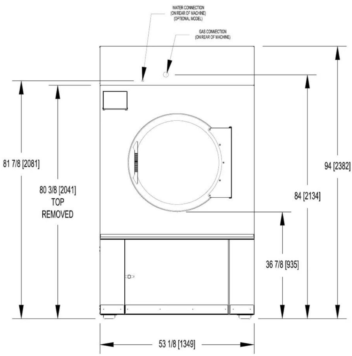
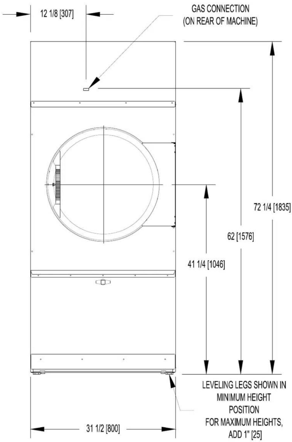
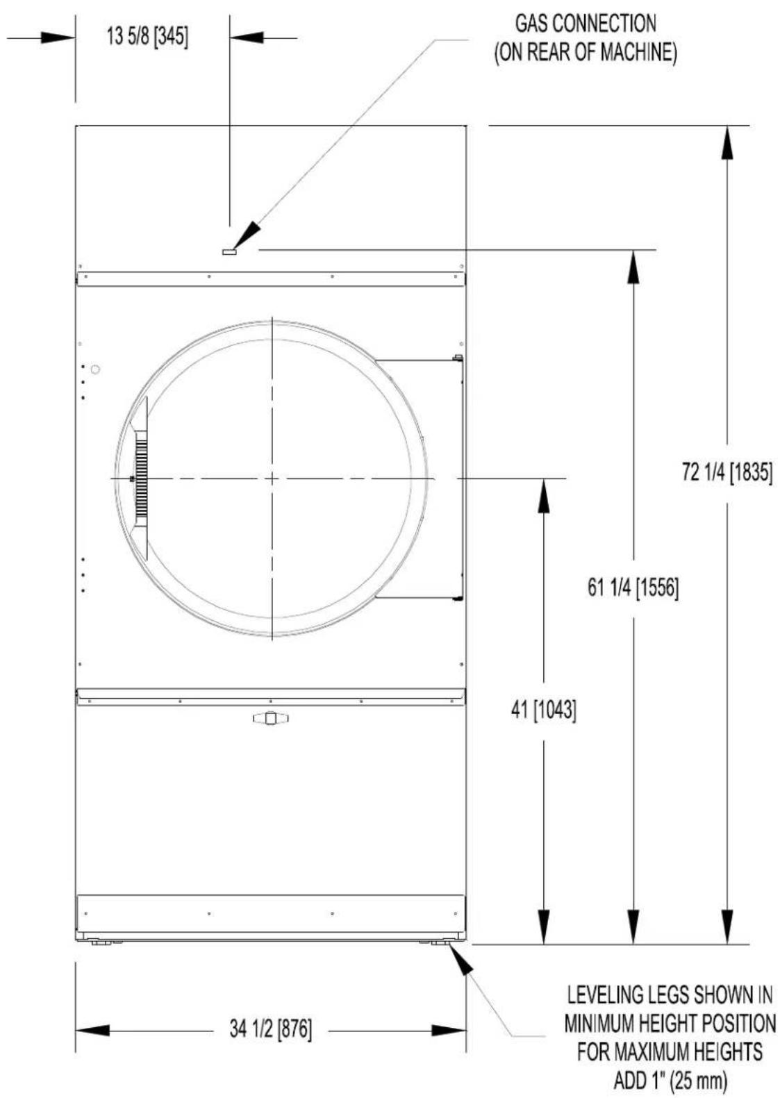
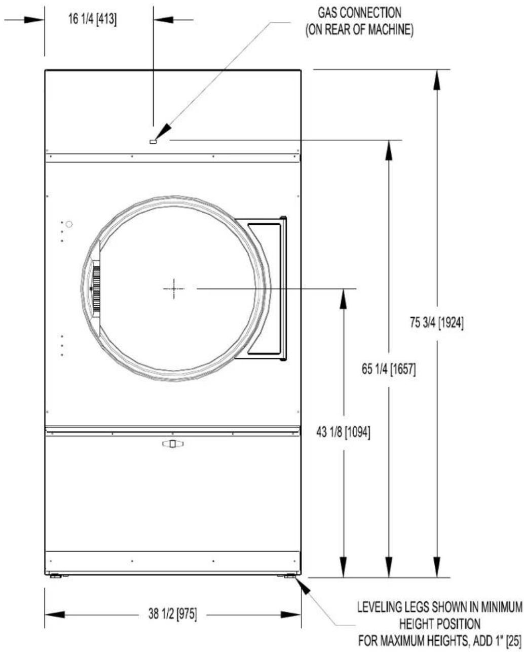
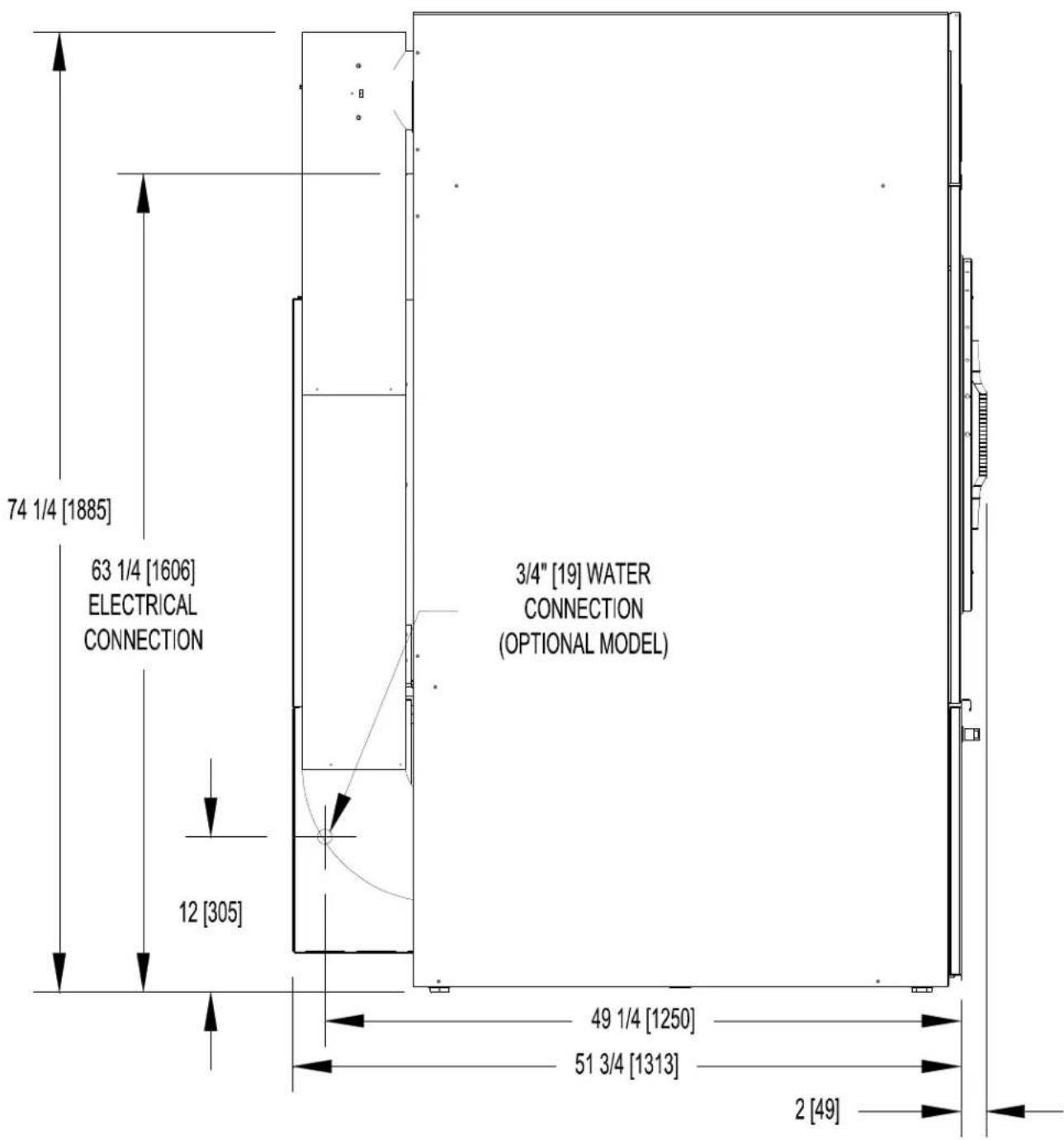
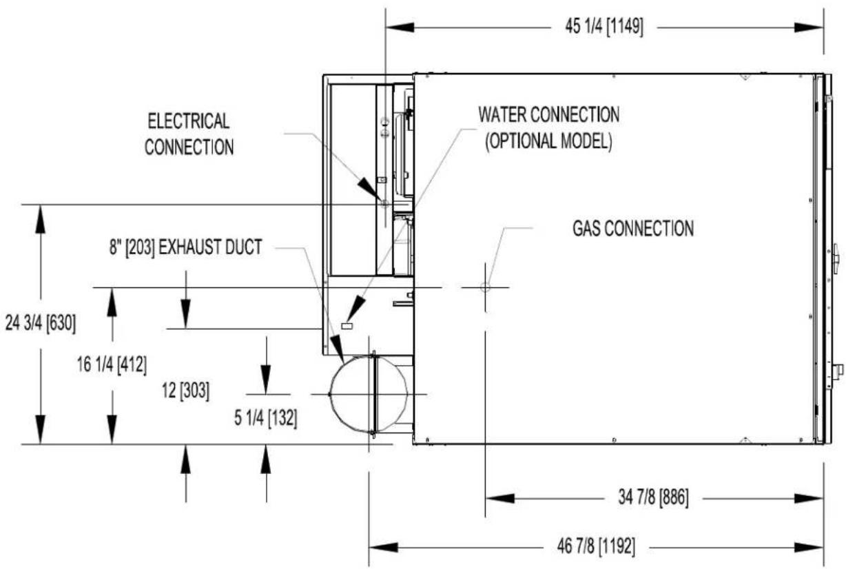
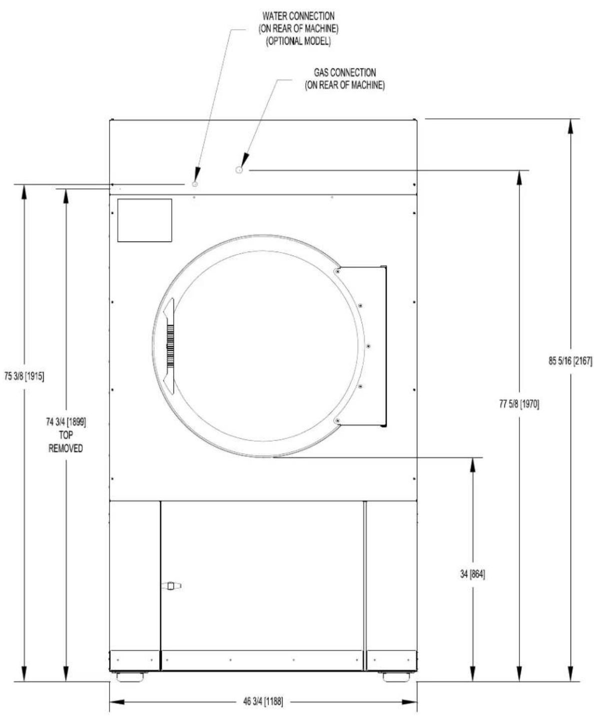
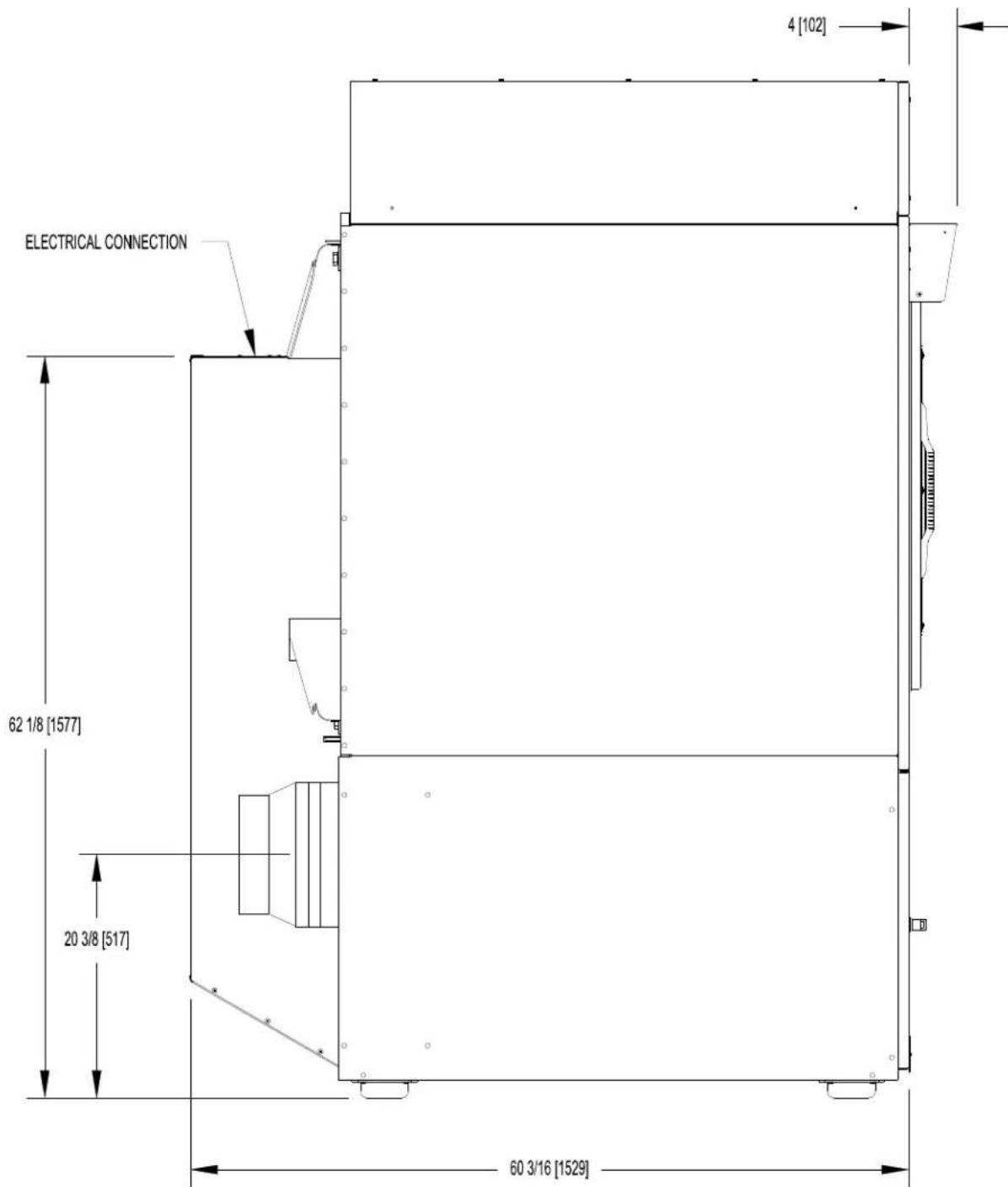
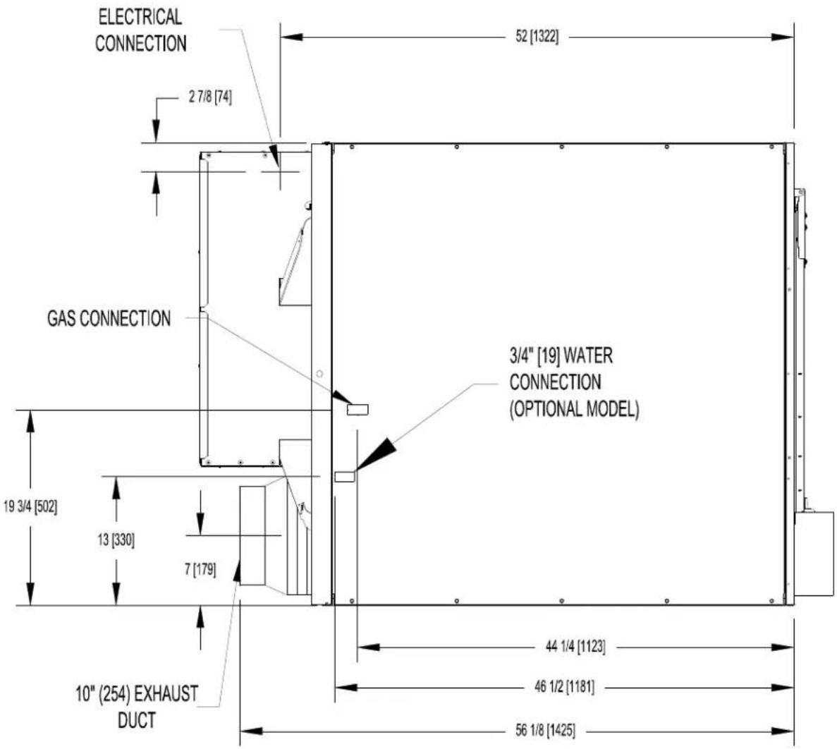
7 T-170 REVERSING DRYER DIMENSIONS
T-170 REVERSING DRYER DIMENSIONS - FRONT VIEW
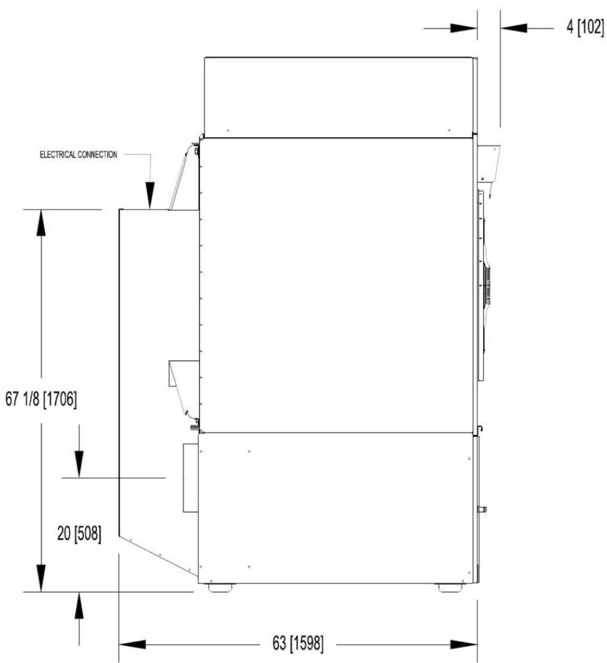
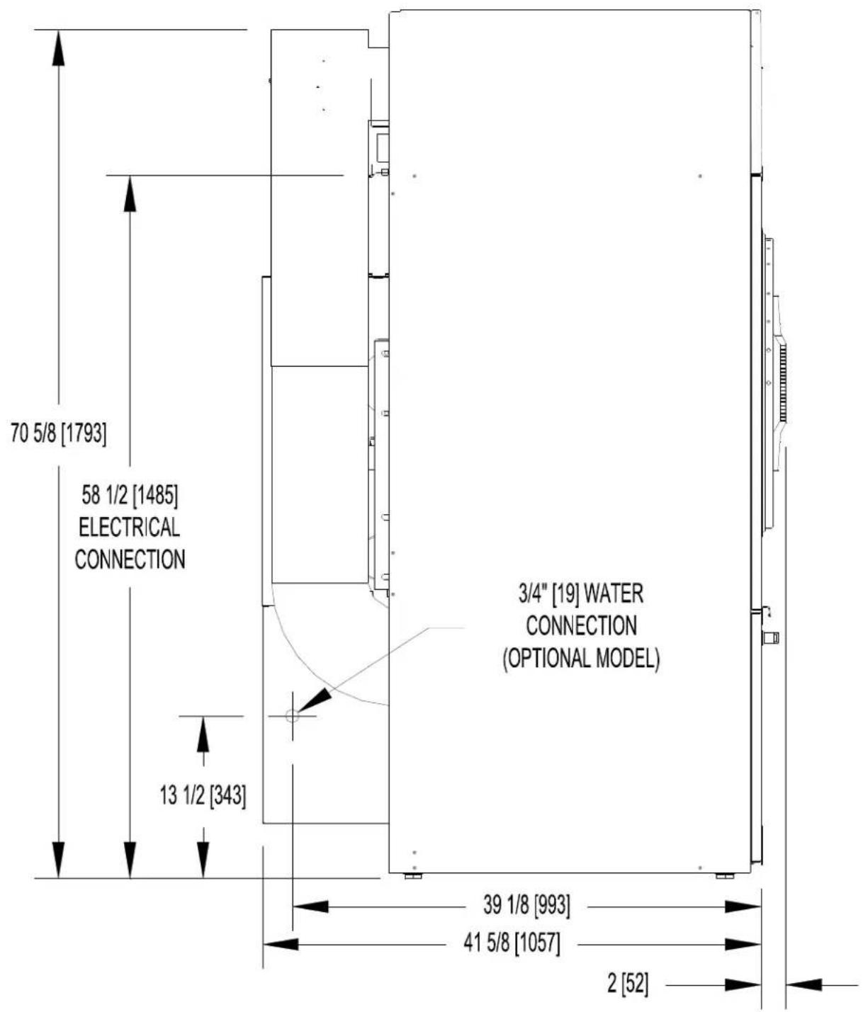
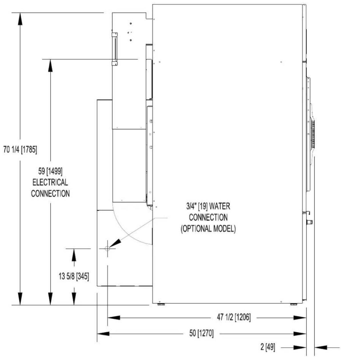
T-170 REVERSING DRYER DIMENSIONS - SIDE VIEW
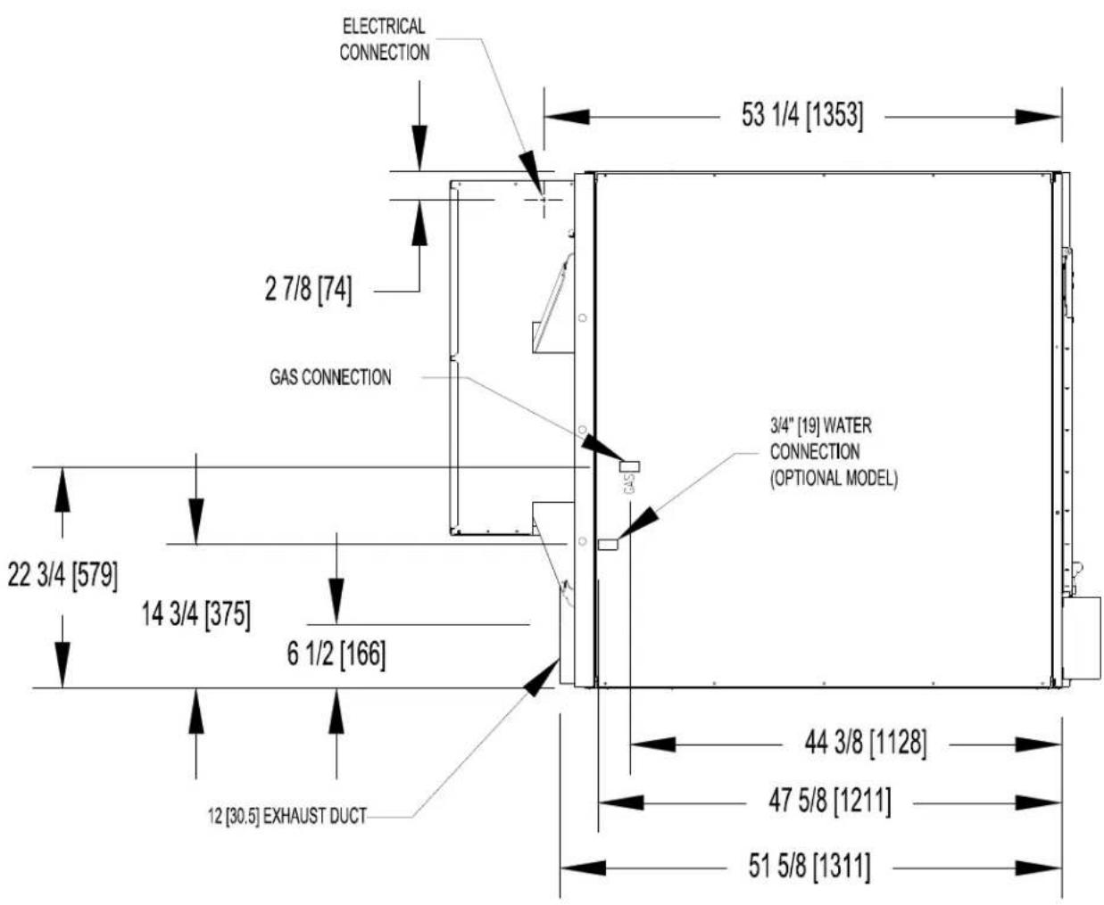
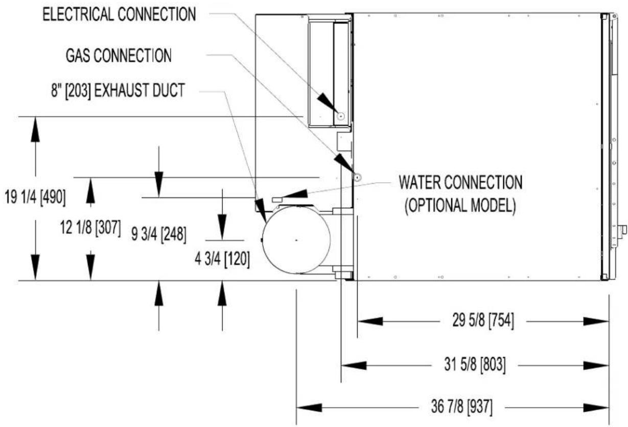
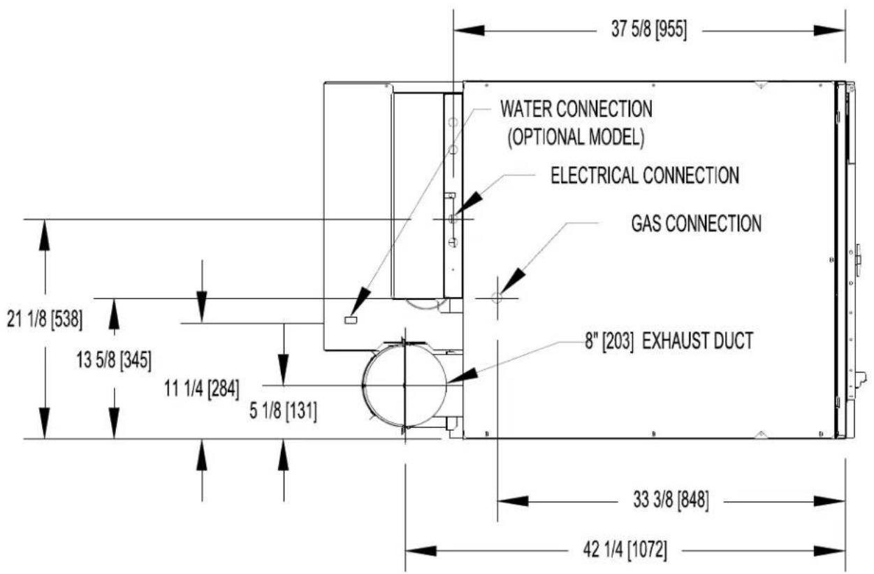
T-170 REVERSING DRYER DIMENSIONS - TOP VIEW
8 INSTALLATION INSTRUCTIONS
8.1 UNCRATING
Tools required: 3 / 4'' hex socket and ratchet driver, knife, channel-lock wrench that opens to 1 3 / 8''
- Remove the plastic wrap with knife. Remove cardboard rails, fillers and top cap.
- Using a ratchet and a 3/4'' socket, remove the (4) bolts attaching the wooden skid to the dryer cabinet. Save the bolts for future moving of the dryer.
- With a walking motion, move the dryer forward completely off the wooden skid. Save the skid for future moving of the dryer.
- T-30/50/80: Using the channel-lock wrench, adjust the leveling legs to align the machine with adjacent units. The T-120 or 170 requires shimming to level the dryer.
Note: If the dryer is ever moved again, the dryer should be re-mounted on its pallet and its crating bolts re-inserted and tightened, in the reverse order as above.
8.2 DRYER INSTALLATION
8.2.1 CODE CONFORMITY
All commercial dryer installations must conform with local codes or, in the absence of local codes, with the latest edition of the National Fuel Gas Code ANSI Z223.1A. Canadian installations must comply with current Standard CAN/CGA-B149 (.1 or .2) Installation Code for Gas Burning Appliances or Equipment, and local codes if applicable. Australian installations must meet installation requirements and pipe sizing requirements of AS/NZA 5601. The appliance, when installed, must be electrically grounded in accordance with the latest edition of the National Electrical Code, ANSI/NFPA70, or, when installed in Canada, with Standard CSA C22.1 Canadian Electrical Code Part 1.
To connect the dryer to the supply piping, use a listed connector in compliance with the Standard for Connectors for Gas Appliances, ANSI Z21.24 · CSA 6.10.
8.2.2 INSTALLATION CLEARANCES
This unit may be installed at the following alcove clearance. (millimeters)
I.LeftSide 0^
II. Right Side 0^ *
III. Back 18^ (457) (Certified for 1'' (25) clearance; however, 18'' (457) clearance is necessary behind the belt guard to allow servicing and maintenance.)
IV. Front 48" (1220) (to allow use of dryer)
V. Top Refer to figure on the next page labeled "Vertical Clearance Dimensions".
AB. Certification allows 0'' clearance for wall framing at the top up to 18" (456 mm) back
from the front.
C. However, a 1/4'' (6 mm) clearance should be allowed so that the upper door can be
opened.
VI. Floor This unit may be installed upon a combustible floor.
*Units may be installed in direct contact with an adjacent dryer, providing allowance is made for opening upper and lower service doors.
8514-291-001 REV PAGE 20
Do not obstruct the flow of combustion and ventilation air.
Maintain minimum of 1^ (25) clearance between duct and combustible material.
Refer to installation label attached to the rear guard of the dryer for other installation information.
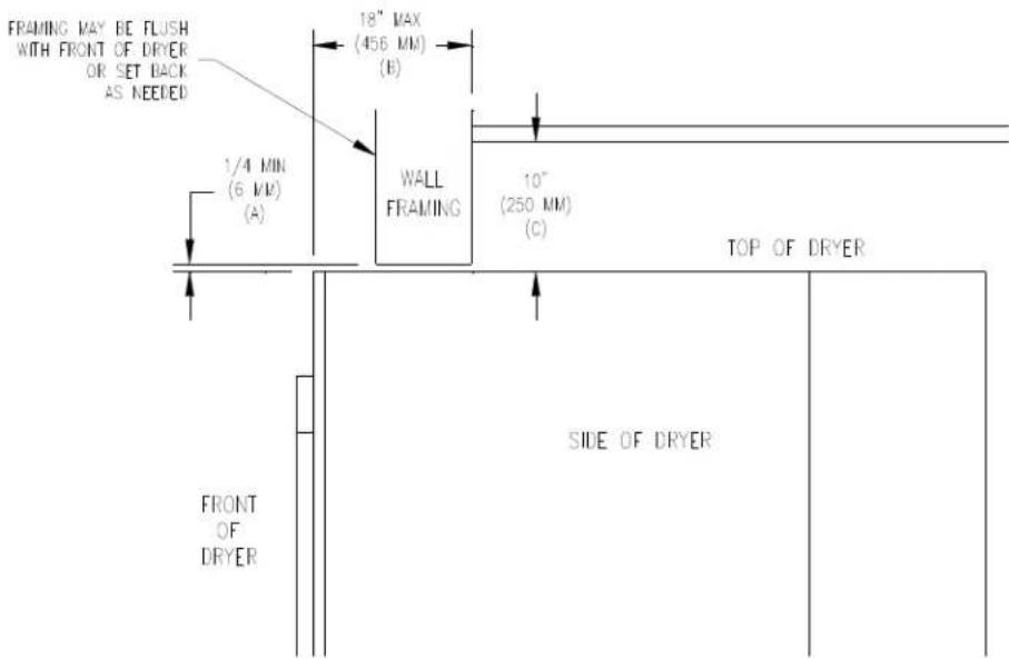
Vertical Clearance Dimensions
8.2.3 MAKE-UP AIR
Adequate make-up air must be supplied to replace air exhausted by dryers on all types of installations. Refer to specifications for the minimum amount of make-up air opening to outside for each dryer. This is a net requirement of effective area. Screens, grills or louver, which will restrict the flow of air, must be considered. Consult the supplier to determine the free area equivalent for the grill being used. The source of make-up air should be located sufficiently away from the dryers to allow an even airflow to the air intakes of all dryers. Multiple openings should be provided.
The sources of all make-up air and room ventilation air movement to all dryers must be located away from any dry cleaners. This is necessary so that solvent vapors will not be drawn into the dryer inlet ducts. Dry cleaner solvent vapors will decompose in contact with open flame such as the gas flame present in clothes dryers. The decomposition products are highly corrosive and will cause damage to the dryer(s) ducts and clothes loads.
8.2.4 ELECTRICAL REQUIREMENTS
The electrical power requirements necessary to operate the unit satisfactorily are listed on the serial plate located on the back panel of each dryer and in the specifications section of this manual. The electrical connection should be made to the terminal board, on the rear of the unit. It is absolutely necessary that the dryer be grounded to a known ground. Individual circuit breakers for each dryer are required. Dryer -15 models are adjusted for 120V as shipped. They can be converted to 208-240V as required. Instructions for this conversion are located at this end of this manual.
Individual circuit breakers for each unit are recommended. Do not use ground-fault circuit breakers or ground-fault circuit interrupter outlets. The wiring diagram is located on the belt guard on the back of the machine.
8.2.5 IMPORTANT: TRANSIENT VOLTAGE SURGE SUPPRESSORS
Like most electrical equipment, your new machine can be damaged or have its life shortened by voltage surges due to lightning strikes which are not covered by factory warranty. Local power distribution problems also can be detrimental to the life of electrical components. We recommend the installation of transient voltage surge
suppressors for your new equipment. These devices may be placed at the power supply panel for the complete installation and don't require an individual device for each machine.
These surge protectors help to protect equipment from large spikes and also from small ongoing spikes in the power that occur on a day to day basis. These smaller surges can shorten overall life of electrical components of all types and cause their failure at a later date. Although they can't protect against all events, these protective devices have a good reputation for significantly lengthening the useful life of electronic components. Electronic components are helped to have a longer useful life when they are supplied with the clean stable electrical power they like.
We are including the following names and phone numbers of a few suppliers of these devices for those who don't currently have a source.
MANUFACTURER
CONTACT
PHONE
Innovative Technology, Inc
Distributor 1-800-809-2772 or
(Part of Eaton Corporation)
www.itvss.com
EFI Electronics Corporation
Factory
1-800-877-1174
(Part of Schneider Electric)
MCG Surge Protection
Factory
1-800-851-1508 or
www
.
n
C
11
ge.con
Advanced Protection
Factory
1-800-237-4567 or
Technologies Inc.
www.aptsurge.com
8.2.6 GAS REQUIREMENTS
The complete gas requirements necessary to operate the dryer satisfactorily are listed on the serial plate located on the back panel of the dryer.
An individual gas shutoff valve is recommended for each dryer and may be required by local code (not supplied).
The inlet gas connection to the unit is 1/2 inch [12.7] pipe thread for T-30/50, 3/4 inch [19.1] for the T-80/T-120 and 1 inch [25.4] for the T-170.
A joint compound resistant to the action of liquefied petroleum gases should be employed in making pipe connections.
All pipe connections should be checked for leakage with soap solution. Never check with an open flame.
A drip tee should be provided in the gas piping entering the unit to catch dirt and other foreign articles.
A 1/8 inch [3.2] NPT threaded test port, accessible for test gage connection, must be installed immediately upstream of the gas supply connection to the dryer to check the supply pressure. Test and adjust the supply pressure to ensure compliance with the specification listed on the serial plate.
The recommended natural gas supply pressure is 7 inches water column (17.8 cm) at each dryer.
There is a plugged 1/8 inch [3.2] NPT threaded test port in the end of the burner manifold for checking the manifold pressure. With the burner in operation, check and adjust the dryer's gas control valve to ensure compliance with the specification listed on the serial plate for manifold pressure.
After testing, be sure to replace the 1/8 inch [3.2] NPT plugs in the manifold and in the supply line test port using joint compound before operating the dryer.
For altitudes above 2,000 feet (610m) it is necessary to de-rate the BTU input. Contact your local distributor for instructions.
L.P. gas conversion kits are available for this dryer. Contact your local distributor.
CAUTION: The dryer must be disconnected from the gas supply piping system during any pressure testing of that system. Do not expose the dryer's gas control valve to testing pressure.
8514-291-001 REV PAGE 22
8.2.7 EXHAUST INSTALLATION
Exhausting of the dryer(s) should be planned and constructed so that no air restrictions occur. Any restriction due to pipe size or type of installation can cause slow drying time, excessive heat, and lint in the room.
From an operational standpoint, incorrect or inadequate exhausting can cause a cycling of the high limit thermostat which shuts off the main burners and results in inefficient drying.
Individual exhausting of the dryers is recommended. All heat, moisture, and lint should be exhausted outside by attaching a pipe of the proper diameter to the dryer adapter collar and extending it out through an outside wall. This pipe must be very smooth on the inside, as rough surfaces tend to collect lint which will eventually clog the duct and prevent the dryer from exhausting properly. All elbows must be smooth on the inside. All joints must be made so the exhaust end of one pipe is inside the next one downstream. The addition of an exhaust pipe tends to reduce the amount of air the blower can exhaust. This does not affect the dryer operation if held within practical limits. For the most efficient operation, it is recommended that no more than 14^ (4.3m) of straight (8" (20.3cm) for T-30/50/80, 10 or 12^ (25.4 or 30.5cm) for T-120), 12^ (30.5cm) for T-170 diameter pipe be used with two right angle elbows. When more than two elbows are used, 2^ (61cm) of straight pipe should be removed for each additional elbow. No more than four right angle elbows should be used to exhaust a dryer.
Maintain minimum 1^ (25) clearance between duct and combustible material.
If the exhaust pipe passes through a wall, a metal sleeve of slightly larger diameter should be set in the wall and the exhaust pipe passed through this sleeve. This practice is required by some local codes and is recommended in all cases to protect the wall. This type of installation should have a means provided to prevent rain and high winds from entering the exhaust when the dryer is not in use. A hood with a hinged damper can be used for this purpose. Another method would be to point the outlet end of the pipe downward to prevent entrance of wind and rain. In either case, the outlet should be kept clear, by at least 24^ (610), of any objects which would cause an air restriction.
Never install a protective screen over the exhaust outlet.
When exhausting a dryer straight up through a roof, the overall length of the duct has the same limits as exhausting through a wall. A rain cap must be placed on top of the exhaust and must be of such a type as to be free from clogging. The type using a cone shaped "roof" over the pipe is suitable for this application.
Exhausting the dryer into a chimney or under a building is not permitted. In either case there is a danger of lint build-up which can be highly combustible.
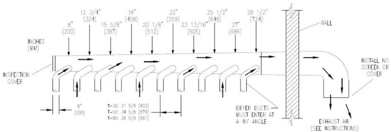
Installation of several dryers, where a main discharge duct is necessary, will need the following considerations for installation. Individual ducts from the dryers into the main discharge duct should be at a 45 degree angle in the direction of discharge air flow.
NOTE: Never install the individual ducts at a right angle into the main discharge duct. The individual ducts from the dryers can enter at the sides or bottom of the main discharge duct. The main duct can be rectangular or round, provided adequate air flow is maintained. For each individual dryer, the total exhausting (main discharge duct plus duct outlet from the dryer) should not exceed the equivalent of 14 feet (4.3m) and two elbows. The diameter of the main discharge duct at the last dryer must be maintained to exhaust end.
NOTE: A small diameter duct will restrict air flow; a large diameter duct will reduce air velocity – both contributing to lint build up. An inspection door should be provided for periodic clean-out of the main duct.
NOTE: STATIC BACK PRESSURE should be a maximum of 0.3 in. w.c. (7.6 mm w.c.) at the rear exhaust outlet of the dryer. If multiple dryers are connected to the common duct, ensure the back draft damper is installed properly.
DIAMETER TO INCREASE AS SHOWN
(For T-30/50/80 only)
For T-30/50/80: the exhaust duct clean-out panel (as shown below) must be closed while the dryer is in service:
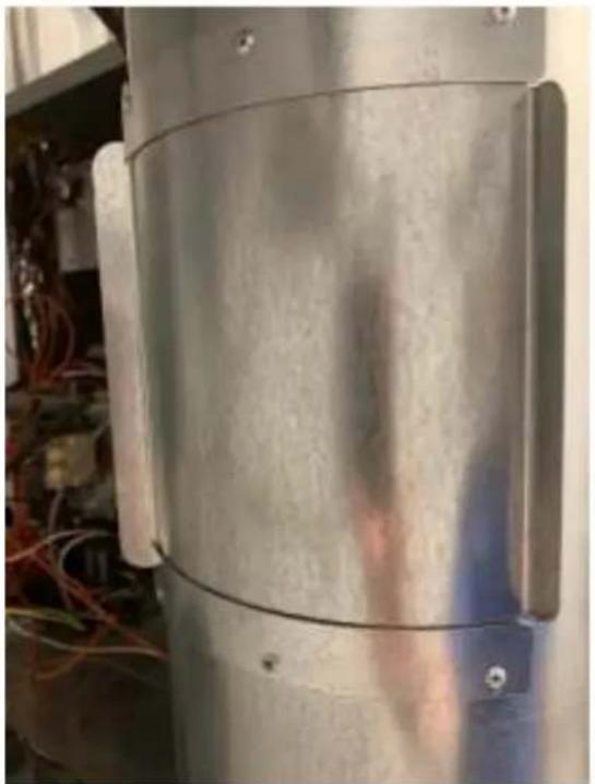
Keep closed while in service
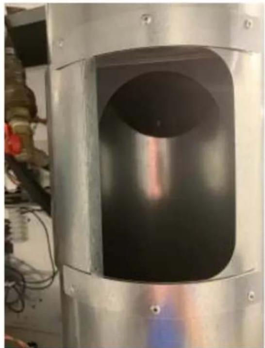
Slide open for routine cleaning
8.3 DRYER IGNITION (SOLID STATE IGNITION)
The solid state ignition system lights the main burner gas by spark. The gas is ignited and burns only when the gas-valve relay (in the electronic controller) calls for heat. The procedure for first-time starting of a dryer is as follows:
A. First, review and comply with the "WARNINGS ABOUT USE AND OPERATION" found on the inside front cover of this manual. Be sure the electrical power supply is connected correctly. The dryer MUST be properly grounded.
B. Make sure all gas supply lines are purged of air. Close the main gas shut-off valve and wait for five minutes before turning the valve back on.
C. Turn on main electrical power switch. The dryer may be started by following the "OPERATING INSTRUCTIONS" found later in this manual.
D. Natural gas and liquefied petroleum gas fired dryers both operate in the same manner. When gas-valve relay contacts are closed (indicating a demand for heat), the solid state ignition control will automatically supply energy to the redundant gas valve. Spark will continue until a flame is detected by the sensing probe, but not longer than 10 seconds. If the gas fails to ignite within 10 seconds, the gas will shut off for 15 seconds. The control will attempt to ignite two more times in a similar manner. If the gas fails to ignite after three tries, the gas valve closes and the system will "lock out". No further attempts at ignition will be performed automatically. It is then necessary to interrupt electrical power to the ignition system before making another attempt to light the burners. This can be done by opening the dryer door, allowing the dryer to come to a stop for 15 seconds, closing the door, and pushing the "Start" button. The dryer will then repeat the ignition trial cycle.
8.4 WATER CONNECTION - OPTIONAL MODEL
An uninterrupted water supply is required for models with the optional water dispensing fire response system. See the dryer dimension section for the location of the water line connection on the rear of the dryer. The thread size on the water valve is 3/4 - 11.5 NHT. The water supply pressure should be 40-120 psi (2.8-8.2 bar). The system will spray at a rate of 6 gallons of water per minute while spraying. A flexible supply line to the dryer is required to prevent damage to the water valve. It is critical to ensure that the room temperature is kept above freezing in the area of the water pipes.
8.5 DRYER SHUTDOWN
To render the dryer inoperative, turn off the main gas shut-off valve and disconnect electrical power to the dryer.
THE INSTALLER MUST TEST THE DRYER FOR OPERATION AND INSTRUCT THE USER BEFORE LEAVING THE INSTALLATION.
9 OPERATING INSTRUCTIONS
9.1 STARTING THE DRYER
9.1.1 Turn on power to the dryer.
9.1.2 Load the laundry.
Place laundry in tumbler and close the door securely. Be sure laundry does not get caught between the door gasket and front panel when closing the door. Maximum load is the dry weight capacity listed in the specification sheet. Do not exceed the listed capacity weight.
9.1.3 Select dry cycle.
Select the appropriate cycle for the type of load being washed. Use the "UP" and "DOWN" keys to change the cycle on the display to the desired cycle and press the enter button to select.
9.1.4 Start dry cycle.
Press enter to start the cycle. The display will show cycle information throughout the cycle.
9.1.5 Pause dry cycle / End dry cycle
Press the red pause button to pause the cycle. Select Start to restart the cycle or select Cancel Cycle to end the dry cycle.
9.2 END OF CYCLE
A tone will sound (if programmed) and the display will indicate that the cycle has ended. Immediately remove contents of dryer. Leave the door open when the machine is not in use.
10 PROGRAMMING / MANAGEMENT VIEW
10.1 ENTER PROGRAMMING MODE
10.1.1 In the cycle selection screen, scroll to Management View at the beginning of the cycle list and select enter.
10.1.2 Enter Passcode and confirm by pressing enter.
10.1.3 Select desired option.
10.1.3.1 Example EDIT CYCLES
Cycles may be edited in the Edit Cycles selection. Within Edit Cycles, cycles may be edited, copied, reordered or deleted.
After making edits, select Back/Exit until out of the option. Confirm changes when prompted to do so. When finished, select Back/Exit until you have returned to the cycle selection screen.
11 AUTODYCYCLES
Autody cycles will dry the load to the programmed percent remaining moisture. Available moisture selections are: 25% , 20% , 15% , 10% , 7% , 5% , 3% , 1% and 0% . These can be changed by editing cycles within the Management View.
When the desired moisture remaining target has been met, the dryer will advance to the next drying stage.
The drying temperature for an Autody cycle is determined by the programmed selection for Material.
Cotton 190 degrees F
- Blend 160 degrees F
Synthetic 140 degrees F
- Wool 140 degrees F
Delicate 120 degrees F
- Ultra-delicate no heat
Autody cycles will perform best with loads of the same material. Performance will vary with mixed-material loads.
12 OVERHEAT SENSING
All O-Series dryers are equipped with an Overheat Sensing System that will detect abnormally rising temperatures. If rising temperatures are detected, the control screen will display OVER TEMPERATURE DETECTED and an alarm will sound. If the loading door is closed, dryer models with reversing tumblers will begin tumbling after 5 seconds.
A 24 VAC output signal will also be sent to the auxiliary terminal block in the control box on the rear of the dryer. This signal is available for customers to use with a supplementary system of their choice.
For dryer models with the optional water-based fire suppression system, water will also intermittently be sprayed into the tumbler.
If the Overheat Sensing System has been activated, the dryer should be inspected safely and appropriately. After inspecting the dryer, it may be returned to service by resetting the controller by pressing the RESET button on the main control board.
13 DRYER ERROR MESSAGES
The O-Series dryer control reacts to various abnormal conditions by displaying an Error message. These messages usually contain the "Error" text, and then a general description of the message. Below is a listing of Error messages separated by each potential displayed message in bold face. Each is following by:
Condition that creates the displayed message on the control
- Action that the control takes responding to the condition
- Exit is the method the user (or the control) should use to bring the machine back to normal operation.
The actual displayed message on the control may contain the general description listed below and additional details (such as number or additional text). However, the condition, action or exit qualities of the error message should be the same for all variations.
For non-reversing models, there is no variable frequency drive. Therefore, any of the error codes listed below that pertain to Drive performance will not be available on those models.
| OPERATION IN PROGRESS | |
| Condition This | error occurs when the user is attempting to start a machine operation while another operation is ending. |
| Action When | detected, the control does not respond to user input on the buttons.There is no delay in the action once the criteria are met. The control will finish the current operation while displaying "OPERATION IN PROGRESS". Once the operation is complete, the error will no longer be displayed, and the control will respond to user input normally. |
| Exit The error | will be reset automatically once the current operation is complete. |
| POWER LOSS | |
| Condition This | error occurs when the Main Control Board detects a total loss of 24VAC power. |
| Action When | detected, the control turns off the motor and the heating relay. There is no delay in the action once the criteria are met. |
| Exit The machine | will not start, and the Error Code will continue to be displayed until the condition is no longer present. Once the condition is removed, the machine still will not start, and the Error Code will continue to be displayed until the prompt is followed to Reset the Error and return the machine to Idle Mode. |
| BROWN OUT | |
| Condition This | error occurs when the Main Control Board detects less than 21VAC at the 24VAC input. |
| Action When | detected, the control turns off the motor and the heating relay. There is no delay in the action once the criteria are met. |
| Exit The machine | will not start, and the Error Code will continue to be displayed until the condition is no longer present. Once the condition is removed, the machine still will not start, and the Error Code will continue to be displayed until the prompt is followed to Reset the Error and return the machine to Idle mode. |
| TEMP SENSOR SHORT | |
| Condition This | error occurs when the control detects a short circuit from the temperature sensor. |
| Action When | detected, the control turns off the motor and the heating relay. There is no delay in the action once the criteria are met. |
| Exit The machine | will not start, and the Error Code will continue to be displayed until the condition is no longer present. Once the condition is removed, the machine still will not start, and the Error Code will continue to be displayed until the prompt is followed to Reset the Error and return the machine to IdleMode. |
| machine still will not start, and the Error Code will continue to be displayed until the prompt is followed to Reset the Error and return the machine to Idle Mode. | |
| TEMP SENSOR OPEN | |
| Condition This error occurs when the control detects an open circuit from the temperature sensor. | |
| Action When detected, the control turns off the motor and the heating relay. There is no delay in the action once the criteria are met. | |
| Exit The machine will not start, and the Error Code will continue to be displayed until the condition is no longer present. Once the condition is removed, the machine still will not start, and the Error Code will continue to be displayed until the prompt is followed to Reset the Error and return the machine to Idle Mode. | |
| NO HEAT RISE | |
| Condition This error occurs when the control detects that the temperature is not increasing. | |
| Action When detected there is a delay of 15 minutes before the error is active. Once active, the control will display the "NO HEAT RISE" prompt, alternating with the normal Cycle Progress screen at a rate of 5 seconds on, 5 seconds off. The heating relay will also be turned off. Otherwise the cycle will continue normally. | |
| Exit The Error Code will continue to be displayed until the in-progress cycle is stopped and the control is returned to Idle Mode. It will then reset automatically. | |
| HEAT RISE OUT OF RANGE | |
| Condition This error occurs when the control detects that the operating temperature is greater than 220 degrees F (or 104 degrees C). | |
| Action When detected, the control will display the "HEAT RISE OUT OF RANGE" prompt, alternating with the normal Cycle Progress screen at a rate of 5 seconds on, 5 seconds off. The heating relay will also be turned off. Otherwise the cycle will continue normally. There is no delay in the action once the criteria are met. | |
| Exit The Error Code will continue to be displayed until the in-progress cycle is stopped and the control is returned to Idle Mode. It will then reset automatically. | |
| CONTROL BOARD ERROR XX | |
| Condition This error occurs when the Main Control Board cannot command the input and outputs of the control system as required by the cycle programming. | |
| Action When detected, the control turns off the motor and the heating relay. There is no delay in the action once the criteria are met. | |
| Exit The machine will not start, and the Error Code will continue to be displayed until the prompt is followed to Reset the Error Code and return the Machine to Idle Mode. If the prompt to Reset is not available, power must be cycled to the machine to reset the error. | |
| GRAPHICS BOARD | |
| Condition This error occurs when the Graphics Board cannot command the Main Control board as required by the cycle programming. | |
| Action When detected, the control turns off the motor and the heating relay. There is no delay in the action once the criteria are met. | |
| Exit The machine will not start, and the Error Code will continue to be displayed until the prompt is followed to Reset the Error Code and return the Machine to Idle Mode. If the prompt to Reset is not available, power must be cycled to the machine to reset the error. | |
| MODEL JUMPER MISSING | |
| Condition This error occurs when there is no connection to Ground (Pin 7) on the Model Jumper Header. | |
| Action When detected, the control turns off the motor and the heating relay. There is no delay in the action once the criteria are met. The machine control checks for this condition when power is cycled and before starting every machine cycle. | |
| Exit The machine will not start, and the Error Code will continue to be displayed until the condition no longer exists and the prompt is followed to Reset the Error Code and return the Machine to Idle Mode. | |
| MODEL JUMPER CHANGED | |
| Condition This error occurs when the jumper connections to Ground (Pin 7) on the Model Jumper Header have changed since the last control check. | |
| Action When detected, the control turns off the motor and the heating relay. There is no delay in the action once the criteria are met. The machine control checks for this condition when power is cycled and before starting every machine cycle. | |
| The machine will not start, and the Error Code will continue to be displayed until the condition no longer exists and the prompt is followed to Reset the Error Code and return the Machine to Idle Mode. | |
| MODEL JUMPER DRIVE SIZE MISMATCH | |
| Condition This error occurs when the jumper connections to Ground (Pin 7) on the Model Jumper Header do not match the VFD size code. | |
| Action When detected, the control turns off the motor and the heating relay. There is no delay in the action once the criteria are met. The machine control checks for this condition when power is cycled. | |
| Exit The machine will not start, and the Error Code will continue to be displayed until the condition no longer exists and the prompt is followed to Reset the Error Code and return the Machine to Idle Mode. | |
| MODEL JUMPER/ DRIVE PARAMETER | |
| Condition This error occurs when the jumper connections to Ground (Pin 7) on the Model Jumper Header do not match the VFD parameters being used. | |
| Action When detected, the control turns off the motor and the heating relay. There is no delay in the action once the criteria are met. The machine control checks for this condition when power is cycled. | |
| Exit The machine will not start, and the Error Code will continue to be displayed until the condition no longer exists and the prompt is followed to Reset the Error Code and return the Machine to Idle Mode. | |
| NON-DEXTER DRIVE | |
| Condition This error occurs when a non-Dexter VFD is installed in the machine. | |
| Action When detected, the control turns off the motor and the heating relay. There is no delay in the action once the criteria are met. The machine control checks for this condition when power is cycled and before starting every machine cycle. | |
| Exit The machine will not start, and the Error Code will continue to be displayed until the condition no longer exists and the prompt is followed to Reset the Error Code and return the Machine to Idle Mode. | |
| DRIVE OVERCURRENT | |
| Condition This error occurs when the control receives a message that the drive has experienced an over current condition. | |
| Action When detected, the control turns off the motor and the heating relay. There is no delay in the action once the criteria are met. | |
| Exit The machine will not start, and the Error Code will continue to be displayed until the condition no longer exists and the prompt is followed to Reset the Error Code and return the Machine to Idle Mode. | |
| DRIVE OVERVOLTAGE | |
| Condition This error occurs when the control receives a message that the drive has experienced an over voltage condition. | |
| Action When detected, the control turns off the motor and the heating relay. There is no delay in the action once the criteria are met. | |
| Exit The machine will not start, and the Error Code will continue to be displayed until the condition no longer exists and the prompt is followed to Reset the Error Code and return the Machine to Idle Mode. | |
| DRIVE OVERHEAT | |
| Condition This error occurs when the control receives a message that the drive has experienced an overheat condition. | |
| Action When detected, the control turns off the motor and the heating relay. There is no delay in the action once the criteria are met. | |
| Exit The machine will not start, and the Error Code will continue to be displayed until the condition no longer exists and the prompt is followed to Reset the Error Code and return the Machine to Idle Mode. | |
| DRIVE OVERLOAD | |
| Condition This error occurs when the control receives a message that the drive has experienced an overload condition. | |
| Action When detected, the control turns off the motor and the heating relay. There is no delay in the action once the criteria are met. | |
| Exit The machine will not start, and the Error Code will continue to be displayed until the condition no longer exists and the prompt is followed to Reset the Error Code and return the Machine to Idle Mode. | |
| DRIVE GROUND FAULT | |
| Condition This error occurs when the control receives a message that the drive has experienced a ground fault condition. | |
| Action When detected, the control turns off the motor and the heating relay. There is no delay in the action once the criteria are met. | |
| Exit The machine will not start, and the Error Code will continue to be displayed until the condition no longer exists and the prompt is followed to Reset the Error Code and return the Machine to Idle Mode. | |
| DRIVE LOW VOLTAGE | |
| Condition This error occurs when the control receives a message that the drive has experienced a low voltage condition. | |
| Action When detected, the control turns off the motor and the heating relay. There is no delay in the action once the criteria are met. | |
| Exit The machine will not start, and the Error Code will continue to be displayed until the condition no longer exists and the prompt is followed to Reset the Error Code and return the Machine to Idle Mode. | |
| DRIVE INTERNAL | |
| Condition This error occurs when the control receives a message that the drive has experienced an internal error. | |
| Action When detected, the control turns off the motor and the heating relay. There is no delay in the action once the criteria are met. | |
| Exit The machine will not start, and the Error Code will continue to be displayed until the condition no longer exists and the prompt is followed to Reset the Error Code and return the Machine to Idle Mode. | |
| DRIVE EXCEPTION | |
| Condition This error occurs when the control receives a message that the drive has logged an exception code. | |
| Action When | detected, the control turns off the motor and the heating relay. There is no delay in the action once the criteria are met. |
| Exit The machine will not start, and the Error Code will continue to be displayed until the condition no longer exists and the prompt is followed to Reset the Error Code and return the Machine to Idle Mode. | |
| DRIVE COMMUNICATION | |
| Condition This error occurs the control cannot communicate with the VFD. | |
| Action When | detected, the control turns off the motor and the heating relay. There is no delay in the action once the criteria are met. |
| Exit The machine will not start, and the Error Code will continue to be displayed until the condition no longer exists and the prompt is followed to Reset the Error Code and return the Machine to Idle Mode. | |
| DRIVE ENABLE | |
| Condition This error occurs when the control sees a message that the VFD Enable circuit is not closed. | |
| Action When | detected, the control turns off the motor and the heating relay. There is no delay in the action once the criteria are met. |
| Exit The machine will not start, and the Error Code will continue to be displayed until the condition no longer exists and the prompt is followed to Reset the Error Code and return the Machine to Idle Mode. | |
| OUT OF SERVICE | |
| Condition This error occurs when the user has designated that the machine control should be made inoperable. | |
| Action When | detected, the control turns off the motor and the heating relay. There is no delay in the action once the criteria are met. |
| Exit The machine will not start, and the Error Code will continue to be displayed the user changes the Out of Service state. | |
| AUTODRY COMMUNICATION 1 | |
| Condition This error occurs when the machine control does not detect CAN communication from the RMC stationary (primary) board. | |
| Action When | detected, there is a delay of 30 5 seconds before the error is active. When active, the control will display the "AUTODRY COMMUNICATION ERROR 1" prompt and the Error Code will continue to be displayed until the cycle ends and the machine returns to Idle Mode. |
| Exit The Error Code will continue to be displayed until the cycle is stopped and the control is returned to Idle mode. | |
| AUTODRY COMMUNICATION 2 | |
| Condition This error occurs when the machine control does not detect wireless communication between the RMC stationary (primary) board and RMC rotating (secondary). | |
| Action When | detected, there is a delay of 5 minutes before the error is active. When active, the control will display the "AUTODRY COMMUNICATION ERROR 2" prompt and the current drying stage will end. The next stage will begin, and the error will continue to be displayed alternating with the Cycle Progress screen during the remainder of the cycle. |
| Exit The Error Code will continue to be displayed until the cycle is stopped and the control is returned to Idle mode. | |
| AUTODRY COMMUNICATION 3 | |
| Condition This error occurs when the machine control does not detect adequate data from the RMC stationary (primary) board. | |
| Action When | detected, there is a delay of 5 minutes before the error is active. When active, the control will display the "AUTODRY COMMUNICATION ERROR 3" prompt and the current drying stage will end. The next stage will begin, and the error will continue to be displayed alternating with the Cycle Progress screen during the remainder of the stage. |
| Exit The Error | Code will continue to be displayed until the cycle is stopped and the control is returned to Idle mode. |
| AUTODRY OOR LOW | |
| Condition This | error occurs when the machine control sees output from the RMC sensor (secondary) board that is out-of-range at 300mV or lower. |
| Action When | detected there is a delay of 5 minutes before the error is active. Once active, the control will display the "AUTODRY OOR LOW" prompt and the current drying stage will end. The next stage will begin, and the error will continue to be displayed alternating with the Cycle Progress screen during the remainder of the stage. |
| Exit The Error | Code will continue to be displayed until the cycle is stopped and the control is returned to Idle mode. |
| OVER TEMPERATURE DETECTED | |
| Condition This | error occurs when an overheat condition has been detected at the OHP sensor |
| Action When | detected there is a calculated delay before the error is active. Once active, the control turns off the heating relays, the control buzzer is turned on, and the alarm relay closes. After 5 seconds, tumbler rotation may occur. If the dryer is equipped with a Fire Suppression system, water may be injected into the dryer cylinder. |
| Exit The Error | Code will continue to be displayed until the condition is no longer present and the mechanical Reset button is pressed on the Main Control board. |
| OVERHEAT SENSOR SHORT | |
| Condition This | error occurs when the control detects a short circuit from the overheat temperature sensor. |
| Action When | detected, the control turns off the motor and the heating relay. There is no delay in the action once the criteria are met. |
| Exit The machine will not start, and the Error Code will continue to be displayed until the condition is no longer present. Once the condition is removed, the machine still will not start, and the Error Code will continue to be displayed until the prompt is followed to Reset the Error and return the machine to Idle Mode. | |
| OVERHEAT SENSOR OPEN | |
| Condition This | error occurs when the control detects an open circuit from the overheat temperature sensor. |
| Action When | detected, the control turns off the motor and the heating relay. There is no delay in the action once the criteria are met. |
| Exit The machine will not start, and the Error Code will continue to be displayed until the condition is no longer present. Once the condition is removed, the machine still will not start, and the Error Code will continue to be displayed until the prompt is followed to Reset the Error, and return the machine to Idle Mode. | |
14 SERVICING THE DRYER
CAUTION: Label all wires prior to disconnection when servicing controls. Wiring errors can cause improper and dangerous operation. Verify proper operation after servicing.
If any of the following symptoms occur on this dryer, check the suggested remedies listed below. If all probable causes have been eliminated and the symptom still exists, contact your local Dexter agent for further troubleshooting assistance. See contact information in Preventative Maintenance section. Parts & Service Manuals from Dexter are also available for further troubleshooting assistance.
| Symptom | Probable Cause | Suggested Remedy |
| Tumbler Does not turn Loading Door Check that Loading Door is completely closed. | ||
| Lint Compartment Door Check that Lint Compartment Door is completely closed. | ||
| Drive Belts Check drive belts for excessive wear. Replace as needed. | ||
| Variable Frequency | Drive Fault | Contact Dexter agent for assistance. |
| Tumbler Turns, but no burner flame is present | Gas shut-off valve Make sure any gas shut-off valve is in the open position. | |
| Ignition Module Follow the procedure for checking the ignition cycle listed in Dryer Ignition section of this manual. | ||
| Slow Drying Control Check that proper Temperature setting is chosen. | ||
| Lint Screen | Clean Lint Screen. | |
| Air flow Restrictions/ | Make-up Air | Follow installation guidelines for static back pressure and make-up air. |
| Exhaust Check exhaust for obstructions, follow installation guidelines. | ||
15 PREVENTIVE MAINTENANCE INSTRUCTIONS
DAILY
- Clean the lint screen. Use a soft brush if necessary.
- Check the lint screen for tears. Replace if necessary.
- Clean lint from the lint screen compartment.
MONTHLY
- Remove lint accumulation from the end bells of the motors.
- Remove lint accumulation from front control area.
- Remove lint and dirt accumulation from the top of the dryer and all areas above, below, and around the burners and burner housing. Failure to keep this portion of the dryer clean can lead to a build-up of lint creating a fire hazard.
- Press test button and check that water sprays into tumbler (optional water-based fire suppression models).
QUARTERLY
- Check the belts for looseness, wear, or fraying.
- Inspect the gasket of the door glass for excessive wear.
- Check tightness of all fasteners holding parts to support channel.
- Check tightness of all set screws.
- Inspect the impeller for tightness of the blades to hub.
- Remove the air flow switch assembly and check the tumbler thru-bolts for tightness.
- Grease the pivot pins and the tension arms where in contact with each other.
- Check water valve and hoses for leaks and wear (optional water-based fire suppression models).
SEMI-ANNUALLY
- Remove and clean the main burners.
- Remove all orifices and examine for dirt and hole obstruction.
- Remove all lint accumulation. Remove the front panel and the lint screen housing and remove lint accumulation.
- Apply a few drops of oil to each spacer tube on the tension arm assembly.
ANNUALLY
- Check the intermediate pulley bearings for wear.
- Check and remove any lint accumulation from the exhaust system.
- Grease the bearings and the shaft of the intermediate drive pulley. Use an Alemite grease gun and Molykote BR2-S grease. (Where applicable)
SERVICE PARTS
PART NUMBER
T-30 NON-REV T-50 REV T-80 NON-REV T-80 REV T-120 REV T-170 REV
DRIVE BELT, MOTOR 9040-076-003 N/A 9040-076-011 9040-076-003 9040-076-008 9040-076-008
DRIVE BELT, TUMBLER 9040-073-009 9040-076-004 9040-073-012 9040-076-012 9040-076-005 9040-082-001
LINT SCREEN FILTER 9822-026-002 9822-026-001 9822-031-002 9822-031-002 9822-033-001 9822-034-001
For service and parts information, contact your local Dexter agent. If a Dexter agent is not available, contact
Dexter Laundry, Inc. directly as listed below:
Mailing Address: 2211 West Grimes Avenue Phone: 1-800-524-2954
Fairfield, IA 52556
USA
Website: www.dexter.com
16 INSTRUCTIONS - CONVERT A DUAL VOLTAGE DRYER FROM 120V to 208-240V
(No Neutral Required) ONLY FOR -15 MODELS
- Remove incoming power from the dryer. Use a known working voltmeter to check power.
- Remove the cover of the control box assembly from the dryer using a 5 / 16'' wrench.
- Move both black/orange wires from the N position of the main power terminal block to the L2 position of the main power terminal block in the control box assembly. See figure below.
- Move the yellow wire in the terminal block to a lower inner right terminal in the control box assembly. See figure below.
- Move the black/orange wire in the terminal block to a lower inner right terminal in the control box assembly. See figure below.
- Move the orange wire in the terminal block to a lower left terminal in the control box assembly. See figure below.
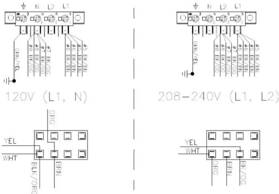
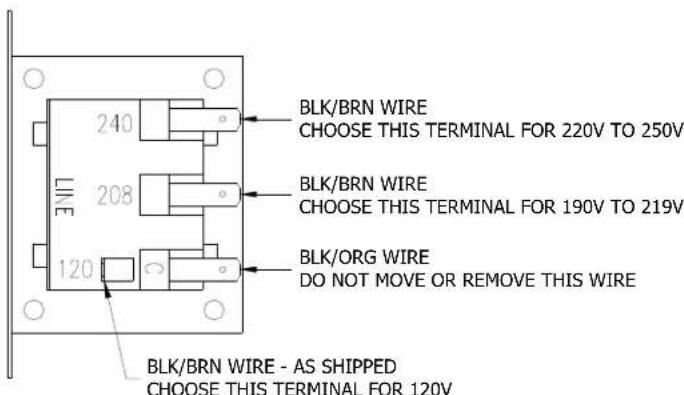
- Move the black/brown wire from the 120V tap on the transformer found in the bottom of control box to the required voltage tap based on actual supply voltage measurement. See figure below.
CONTROL TRANSFORMER CONNECTIONS AS VIEWED FROM SIDE OF TRANSFORMER
- Reconnect power to the dryer and test to ensure proper operation; one line voltage to L1, one line voltage to L2 and the earth ground to the terminal showing the ground symbol.
- Reinstall the cover of the control box assembly on the dryer using a 5 / 16'' wrench.
8514-291-001 REV PAGE 35
MANUEL DE L'UTILISATEUR
INSTRUCTIONS D'INSTALLATION ET D'UTILISATION
Failure to follow safety warnings exactly could result in serious injury, death or property damag
- Do not store or use gasoline or other flammable vapors and liquids in the vicinity of this or any other appliance.
WHAT TO DO IF YOU SMELL GAS
- Do not try to light any appliance.
- Do not touch any electrical switch; do not use any phone in your building.
- Clear the room, building or area of all occupants.
- Immediately call your gas supplier from a neighbor's phone. Follow the gas supplier's instructions.
-
If you cannot reach your gas supplier, call the fire department.
-
Installation and service must be performed by a qualified installer, service agency or the gas supplier.
Do not store or use gasoline or other flammable vapors or liquids in the vicinity of this or any other appliance.
24.2.1 CONFORMITE AU CODE
2211 West Grimes Avenue
Telephone :
1-800-524-2954
Fairfield, IA 52556
États-Unis
Site web: www.dexter.com