T30x2 - Tumble drier Dexter Laundry - Free user manual and instructions
Find the device manual for free T30x2 Dexter Laundry in PDF.
User questions about T30x2 Dexter Laundry
0 question about this device. Answer the ones you know or ask your own.
Ask a new question about this device
Download the instructions for your Tumble drier in PDF format for free! Find your manual T30x2 - Dexter Laundry and take your electronic device back in hand. On this page are published all the documents necessary for the use of your device. T30x2 by Dexter Laundry.
USER MANUAL T30x2 Dexter Laundry
The dryer must not be stored or installed where it will be exposed to water and/or weather.
WARNING:
FIRE OR EXPLOSION HAZARD
Failure to follow safety warnings exactly could result in serious injury, death or property damage.
-
Do not store or use gasoline or other flammable vapors and liquids in the vicinity of this or any other appliance.
WHAT TO DO IF YOU SMELL GAS -
Do not try to light any appliance.
- Do not touch any electrical switch; do not use any phone in your building.
- Clear the room, building or area of all occupants.
- Immediately call your gas supplier from a neighbor's phone. Follow the gas supplier's instructions.
-
If you cannot reach your gas supplier, call the fire department.
-
Installation and service must be performed by a qualified installer, service agency or the gas supplier.
Post the following "For Your Safety" caution in a prominent location:
FOR YOUR SAFETY
Do not store or use gasoline or other flammable vapors or liquids in the vicinity of this or any other appliance.
It is important that you read this Manual and retain it for future reference. For service or replacement parts, contact the distributor in your area or the manufacturer.
You, the purchaser, must post in a prominent location instructions to be followed in the event the user smells gas. Consult your local gas supplier for procedure to be followed if the odor of gas is present.
TABLE OF CONTENTS
| Page No. | |
| Warnings about use and operation 2 | |
| Dryer Specifications 3-6 | |
| Dryer Dimensions 7-15 | |
| Installation Instructions 16-20 | |
| Dryer Shutdown 20 | |
| Description of Dryer Control 21-22 | |
| Dryer Fault Codes 23 | |
| Operating Instructions 27 | |
| Programming the Dryer Control 28 | |
| Servicing and Troubleshooting 39 | |
| Preventative Maintenance Instructions 40 | |
| Dual Voltage Conversion Instructions 41 |
WARNING ABOUT USE AND OPERATION
DO NOT MODIFY THIS APPLIANCE. KEEP SHIELDS, GUARDS, AND COVERS IN PLACE. These safety devices are provided to protect everyone from injury.
It is ABSOLUTELY ESSENTIAL that the dryer be grounded to a known earth (zero) ground in accordance with local codes or, in the absence of local codes, with the latest editions of the National Electric Code, ANSI//NFPA 70 or Standard CSA C22.1 Canadian Electrical Code Part 1. This is not only for personal safety, but is necessary for proper operation of the controller. Failure to do so will void the warranty of the controller.
A DRYER SHOULD BE CONNECTED TO POWER FOR THREE (3) MINUTES before it is operated or before a program change is made. Operation or program changes, which occur during this "power up" period, are subject to loss in case of power interruption. After the initial three minutes, all programmed data is protected from power interruptions of any length and the customer's individual cycle is protected up to 3 seconds. This is done without batteries.
LEAVE THE ELECTRICAL POWER TO THE DRYER ON AT ALL TIMES except when necessary for service or other similar activities. The hour meter function adds only full hours to its reading. If the power is shut off every night, any fraction of an hour of time that is on the machine at that time will be lost. Turning the power off every night could also have some effect on the long-term life of the memory after a number of years. Turning power off occasionally won't affect the unit.
THIS DRYER IS EQUIPPED WITH AN OVER-TEMPERATURE THERMOSTAT located on the side of the burner housing for T-30X2 and T-50X2 above the gas valve (located on side of exhaust duct for T-20X2 below burner housing). Should the dryer cease to operate, refer to your "Service Procedure and Parts Data" book for instructions.
CHECK THIS THERMOSTAT WHEN INSTALLING DRYER to assure it is not tripped. Impacts such as rough handling in shipment, may trip the thermostat. It may be reset by inserting a wooden pencil or dowel through the bushing in the cover. Note: there is no cover on the T-20X2 model.
DO NOT SPRAY AEROSOLS IN THE VICINITY OF THIS APPLIANCE while in operation.
THIS APPLIANCE SHALL NOT BE USED TO DRY OFF SOLVENTS OR DRY-CLEANING FLUIDS.
SPECIFICATIONS
20 Ib. Commercial Stack Dryer: T-20X2 - DN20X2N_-15EB_X (60 Hz), DN20X2N_-39AB_X (50 Hz)
Cabinet Height 68 1/2" 1740 mm.
(Assumes minimum leveling leg adjustment)
Cabinet Width 27" 686 mm.
Cabinet Depth 44 5/8" 1133 mm.
Floor to Bottom of Door-Bottom Dryer 81/2" 216 mm.
Floor to Bottom of Door-Top Dryer 42" 1067 mm.
Door Opening 18 1/8" 460 mm.
Dry Wt. Capacity 20 x 2 lbs. 9.1 x 2 kg.
Cylinder Diameter 25 1/2" 648 mm.
Cylinder Depth 24" 610 mm.
Cylinder Volume 7.0 cu. ft. 198 liters
Lint Screen Area 285 sq. in. 1839 sq. cm.
Gas Input (per dryer- 60 hz) 56,000 Btu/hr 59MJ/hr (16.4 kW)
Gas Input (per dryer- 50 hz) 47,000 Btu/hr 50MJ/hr (13.8 kW)
Gas Supply Connection 1/2" 12.7 mm.
Natural Gas Supply (Water Column) 5" - 8" 127 mm. - 203 mm./1.25kPa - 1.99kPa
Natural Burner Manifold
(60 hz Water Column) 3.5" 88.9 mm./0.87kPa
(50 hz Water Column) 3.5" 88.9 mm./0.87kPa
Propane or ULPG Supply (Water Column) 11.5" - 13.5" 292 mm. - 343 mm./2.86kPa - 3.36kPa
Burner Manifold Pressure
Propane (60 hz Water Column) 11" 279 mm./2.75kPa
Propane or ULPG (50 hz Water Column) 11" 279 mm./2.75kPa
Exhaust Size 8" 203 mm.
Make-up Air 1.0 sq. ft. 929 sq. cm.
Example: 1.0 sq. ft = 1 ft. long X 1 ft. wide
Motor Size (per dryer) 1/3 H.P. .248 kW
Airflow (per dryer - 60 hz) 370 CFM 10.5 m^3/min
Airflow (per dryer - 50 hz) 300 CFM 8.5 m^3/min
Electrical Specifications - 120/60/1
Voltage/Hz/Phase 120V/60Hz/1Phase
RunningAmps 7.8
Circuit ProtectionAmps 20
Wire Size 12 gauge
Electrical Service 2 wire + ground
Electrical Specifications - 208-240/60/1
Voltage/Hz/Phase 208-240V/60Hz/1Phase
RunningAmps 3.8
Circuit Protection Ams 15
Wire Size 12 gauge
Electrical Service 2 wire + ground
Electrical Specifications - 230/50/1
Voltage/Hz/Phase 230V/50Hz/1Phase
RunningAmps 6.6
Circuit Protection Ams 15
Wire Size 12 gauge
Electrical Service 2 wire + ground
Shipping Weight 650 lbs. 295 kg.
Net Weight 615 lbs. 279 kg.
Clearance Behind Machines (min.) 18" 457 mm.
SPECIFICATIONS
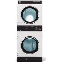
30 lb. Industrial Stack Dryer: T-30X2 - DN30X2N_-15EB_X (60 Hz), DN30X2N_-39AB_X (50 Hz)
Cabinet Height 76 1/4" 1937 mm.
(Assumes minimum leveling leg adjustment)
Cabinet Width 31 1/2" 800 mm.
Cabinet Depth 49 1/2" 1257 mm.
Floor to Bottom of Door- Bottom Dryer 7 5/8" 194 mm.
Floor to Bottom of Door-Top Dryer 45 1/4" 1149 mm.
Door Opening 22 5/8" 575 mm.
Dry Wt. Capacity 30 × 2 lbs. 13.6 × 2 ~kg .
Cylinder Diameter 30" 762 mm.
Cylinder Depth 27 1/2" 699 mm.
Cylinder Volume 11.25 cu. ft. 319 liters
Lint Screen Area 453 sq. in. 2923 sq. cm.
Gas Input (per dryer- 60 hz) 90,000 Btu/hr 95MJ/hr (26.4 kW)
Gas Input (per dryer- 50 hz) 74,000 Btu/hr 78MJ/hr (21.7 kW)
Gas Supply Connection 1/2" 12.7 mm.
Natural Gas Supply (Water Column) 5" - 8" 127 mm. - 203 mm./1.25kPa - 1.99kPa
Natural Burner Manifold
(60hzWater Column) 3.5" 88.9mm./0.87kPa
(50hzWater Column) 3.4" 86.4 mm./0.84kPa
Propane or ULPG Supply (Water Column) 11.5" - 13.5" 292 mm. - 343 mm./2.86kPa - 3.36kPa
Burner Manifold Pressure
Propane (60 hz Water Column) 11" 279 mm./2.75kPa
Propane or ULPG (50 hz Water Column) 10" 254 mm./2.50kPa
Exhaust Size 8" 203 mm.
Make-up Air 1.5 sq.ft. 1394 sq.cm.
Example: 1.5 sq. ft = 1 ft. long X 1.5 ft. wide
Motor Size 1/2 H.P. .373 kW
Airflow (60 hz) 600 CFM 17.0m^3 / min
Airflow (50 hz) 500 CFM 14.2 m^3/min
Electrical Specifications - 120/60/1
Voltage/Hz/Phase 120V/60Hz/1Phase
RunningAmps 8.0
Circuit Protection Ams 20
Wire Size 12 gauge
Electrical Service 2 wire ^+ ground
Electrical Specifications - 208-240/60/1
Voltage/Hz/Phase 208-240V/60Hz/1Phase
RunningAmps 5.0
Circuit ProtectionAmps 15
Wire Size 12 gauge
Electrical Service 2 wire + ground
Electrical Specifications - 230/50/1
Voltage/Hz/Phase 230V/50Hz/1Phase
RunningAmps 10.0
Circuit Protection Ams 15
Wire Size 12 gauge
Electrical Service 2 wire + ground
Shipping Weight 750 lbs. 340 kg.
Net Weight 699 lbs. 317 kg.
Clearance Behind Machines (min.) 18" 457 mm.
SPECIFICATIONS
50 lb. Industrial Stack Dryer: T-50X2 - DN50X2N_-15EB_X (60 Hz), DN50X2N_-39AB_X (50 Hz)
Cabinet Height 79 1/4" 2012 mm.
(Assumes minimum leveling leg adjustment)
Cabinet Width 34 1/2" 876 mm.
Cabinet Depth 54 3/4" 1391 mm.
Floor to Bottom of Door-Bottom Dryer 7" 178 mm.
Floor to Bottom of Door-Top Dryer 46" 1168 mm.
Door Opening 25 5/8" 651 mm.
Dry Wt. Capacity 50 x 2 lbs. 22.7 x 2 kg.
Cylinder Diameter 32 1/2" 826 mm.
Cylinder Depth 33" 838 mm.
Cylinder Volume 15.84 cu. ft. 448 liters
Lint Screen Area 544 sq. in. 3510 sq. cm.
Gas Input (per dryer- 60 hz) 108,000 Btu/hr 114MJ/hr (31.7 kW)
Gas Input (per dryer- 50 hz) 96,500 Btu/hr 102MJ/hr (28.3 kW)
Gas Supply Connection 1/2" 12.7 mm.
Natural Gas Supply (Water Column) 5" - 8" 127 mm. - 203 mm./1.25kPa - 1.99kPa
Natural Burner Manifold
(60 hz Water Column) 3.5" 88.9 mm./0.87kPa
(50hzWater Column) 3.5" 88.9mm./0.87kPa
Propane or ULPG Supply (Water Column) 11.5" - 13.5" 292 mm. - 343 mm./2.86kPa - 3.36kPa
Burner Manifold Pressure
Propane (60 hz Water Column) 11" 279 mm./2.75kPa
Propane or ULPG (50 hz Water Column) 10^ 254 mm./2.40kPa
Exhaust Size 8" 203 mm.
Make-up Air 1.5 sq.ft. 1394 sq.cm.
Example: 1.5 sq. ft = 1 ft. long X 1.5 ft. wide
Motor Size 3/4 H.P. .560 kW
Airflow (60 Hz) 650 CFM 18.4m^3 / min
Airflow (50 Hz) 510 CFM 14.4 m^3/min
Electrical Specifications - 120/60/1
Voltage/Hz/Phase 120V/60Hz/1 Phase
RunningAmps 20.0
Circuit ProtectionAmps 30
Wire Size 10 gauge
Electrical Service 2 wire + ground
Electrical Specifications - 208-240/60/1
Voltage/Hz/Phase 208-240V/60Hz/1Phase
RunningAmps 10.0
Circuit ProtectionAmps 20
Wire Size 12 gauge
Electrical Service 2 wire + ground
Electrical Specifications - 230/50/1
Voltage/Hz/Phase 230V/50Hz/1Phase
RunningAmps 10.0
Circuit Protection Ams 20
Wire Size 12 gauge
Electrical Service 2 wire + ground
Shipping Weight 917 lbs. 416 kg.
Net Weight 857 lbs. 389 kg.
Clearance Behind Machines (min.) 18" 457 mm.
SPECIFICATIONS
50 lb. Industrial Stack Dryer: T-50x2 Reversing Tumbler DN50X2N_-11EB2R (60 Hz), DN50X2N_-39AB2R (50 Hz)
Cabinet Height 79 1/4" 2012 mm.
(Assumes minimum leveling leg adjustment)
Cabinet Width 34 1/2" 876 mm.
Cabinet Depth 54 3/4" 1391 mm.
Floor to Bottom of Door-Bottom Dryer 7" 178 mm.
Floor to Bottom of Door-Top Dryer 46" 1168 mm.
Door Opening 25 5/8" 651 mm.
Dry Wt. Capacity 50 × 2 lbs. 22.7 × 2 kg.
Cylinder Diameter 32 1/2" 826 mm.
Cylinder Depth 33" 838 mm.
Cylinder Volume 15.84 cu. ft. 448 liters
Lint Screen Area 544 sq. in. 3510 sq. cm.
Gas Input (per dryer- 60 hz) 108,000 Btu/hr 114MJ/hr (31.7 kW)
Gas Input (per dryer- 50 hz) 96,500 Btu/hr 102MJ/hr (28.3 kW)
Gas Supply Connection 1/2" 12.7 mm.
Natural Gas Supply (Water Column) 5" - 8" 127 mm. - 203 mm./1.25kPa - 1.99kPa
Natural Burner Manifold
(60 hz Water Column) 3.5" 88.9 mm./0.87kPa
(50hzWater Column) 3.5" 88.9mm./0.87kPa
Propaneor ULPG Supply (Water Column) 11.5" - 13.5" 292 mm. - 343 mm./2.86kPa - 3.36kPa
Burner Manifold Pressure
Propane (60 hz Water Column) 11" 279 mm./2.75kPa
Propane or ULPG (50 hz Water Column) 10^ 254 mm./2.40kPa
Exhaust Size 8" 203 mm.
Make-up Air 1.5 sq.ft. 1394 sq.cm.
Example: 1.5 sq. ft = 1 ft. long X 1.5 ft. wide
Motor Sizes 1/2 & 2 H.P. .373 & 1.492 kW
Airflow (60 Hz) 650 CFM 18.4m^3 / min
Airflow (50 Hz) 510 CFM 14.4 m^3/min
Electrical Specifications - 208-240/60/1
Voltage/Hz/Phase 208-240V/60Hz/1Phase
RunningAmps 15.0
Circuit Protection Ams 20
Wire Size 12 gauge
Electrical Service 3 wire + ground
Electrical Specifications - 230/50/1
Voltage/Hz/Phase 230V/50Hz/1Phase
RunningAmps 15.0
Circuit Protection Ams 20
Wire Size 12 gauge
Electrical Service 2 wire + ground
Shipping Weight 917 lbs. 416 kg.
Net Weight 857 lbs
Clearance Behind Machines (min.) 18" 457 mm.
DIMENSIONS ARE IN INCHES [MILLIMETERS]
T-20X2 DRYER DIMENSIONS - SIDE VIEW
DIMENSIONS ARE IN INCHES [MILLIMETERS]
T-20X2 DRYER DIMENSIONS - REAR VIEW
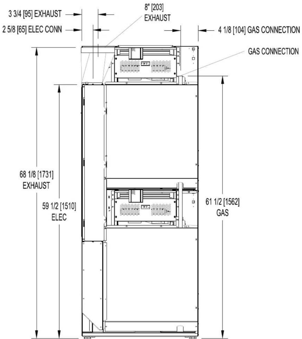
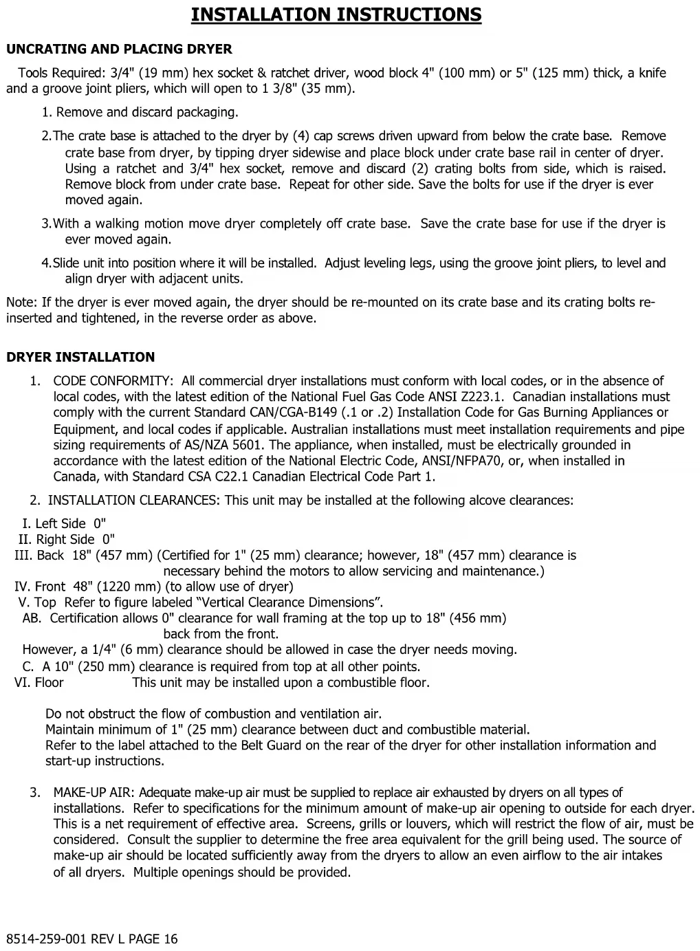
DIMENSIONS ARE IN INCHES [MILLIMETERS]
T-30X2 DRYER DIMENSIONS-FRONT VIEW

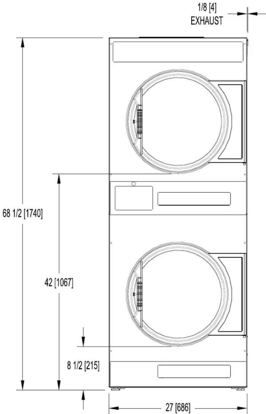
DIMENSIONS ARE IN INCHES [MILLIMETERS]
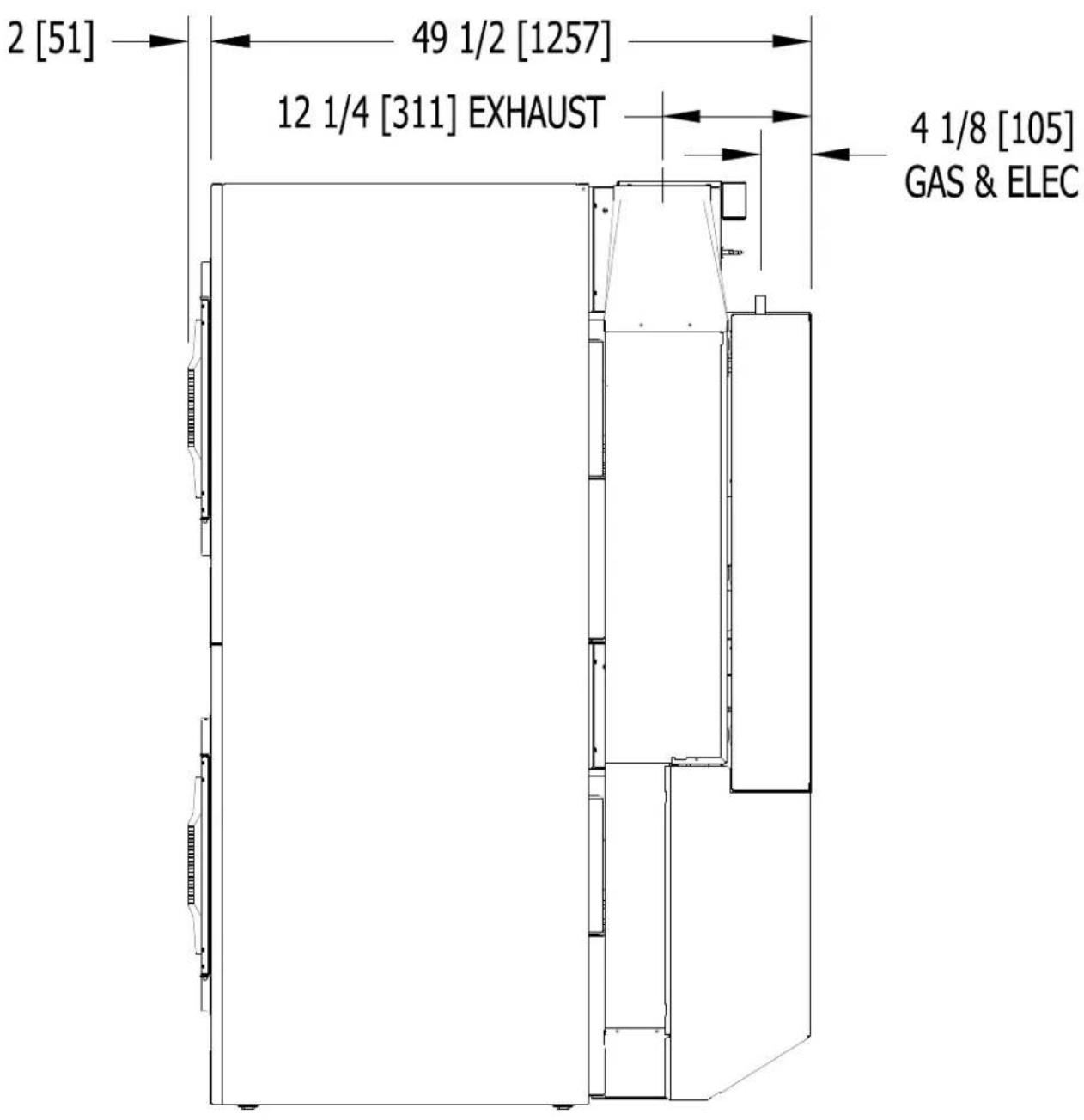
T-30X2 DRYER DIMENSIONS - SIDE VIEW
DIMENSIONS ARE IN INCHES [MILLIMETERS]
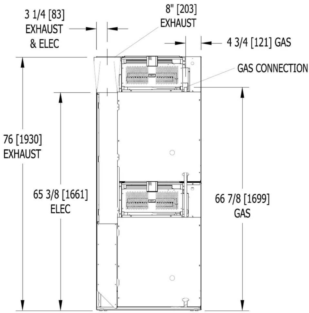
T-30X2 DRYER DIMENSIONS - REAR VIEW
DIMENSIONS ARE IN INCHES [MILLIMETERS]
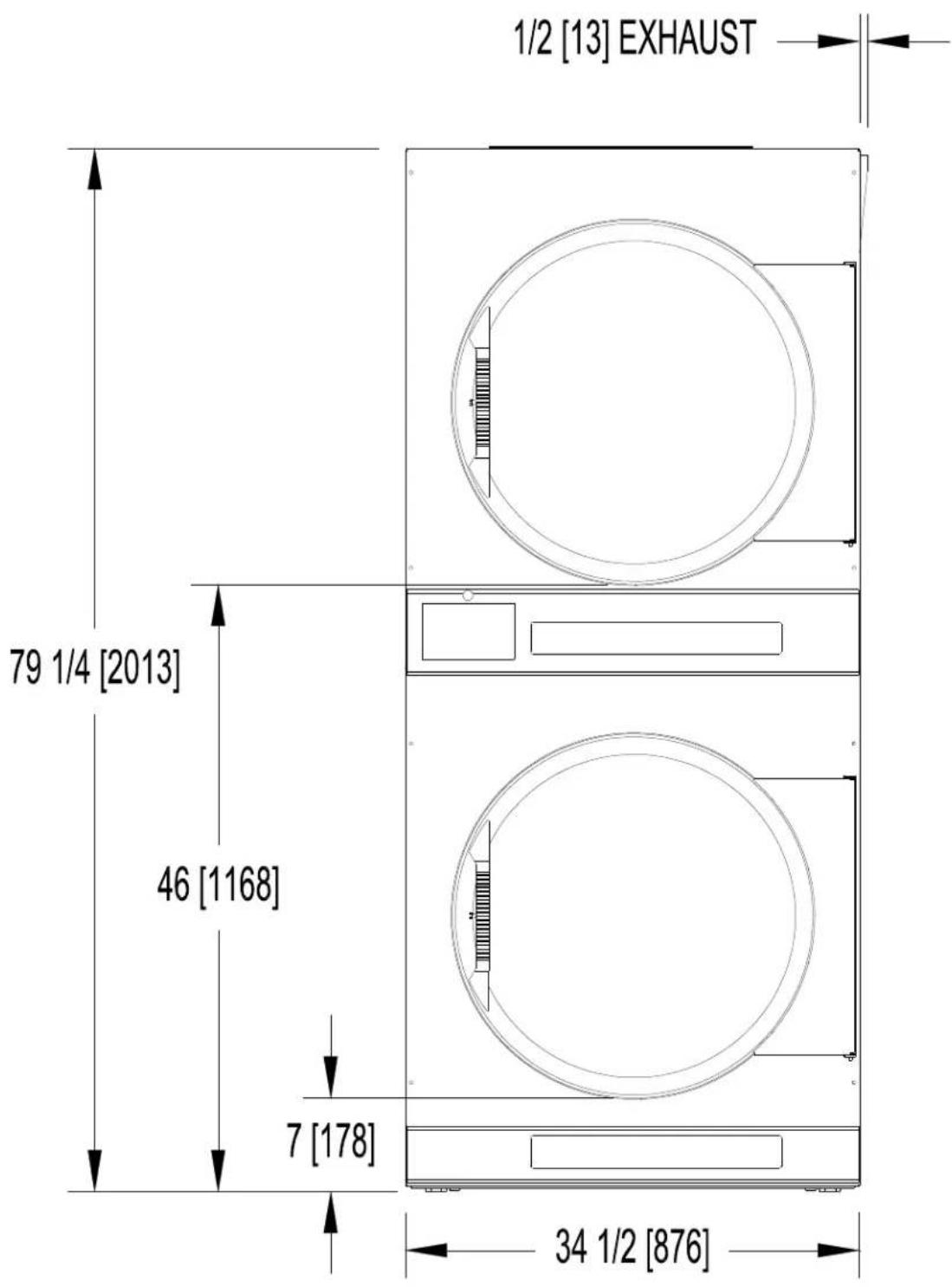
T-50X2 DRYER DIMENSIONS-FRONT VIEW
DIMENSIONS ARE IN INCHES [MILLIMETERS]
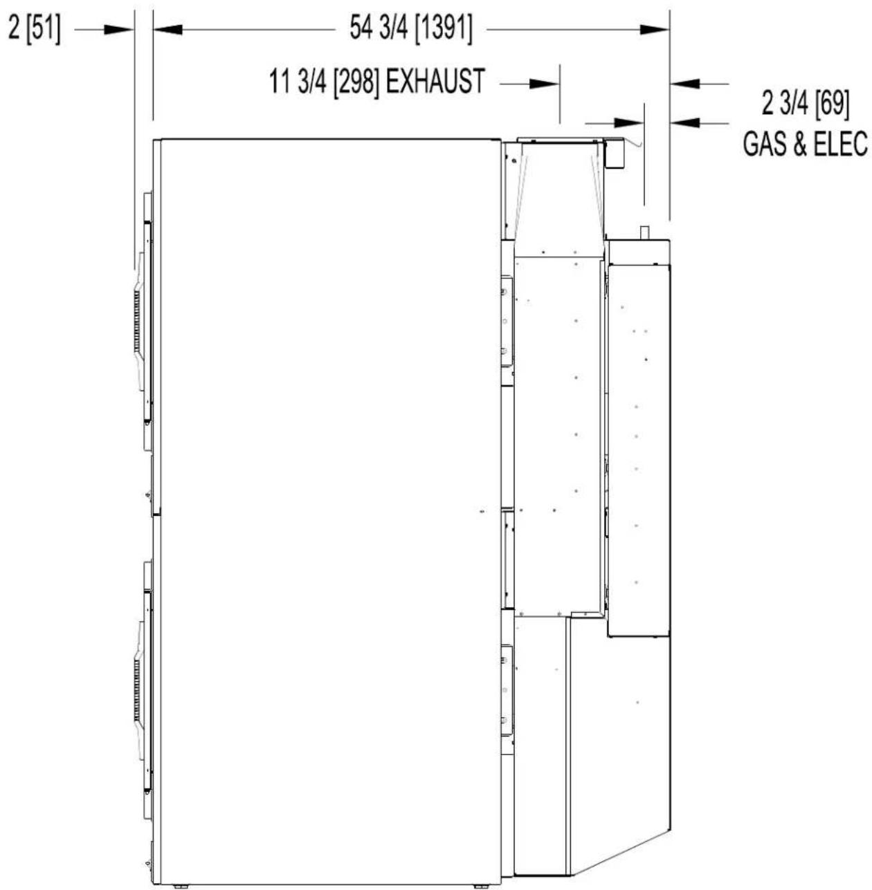
DIMENSIONS ARE IN INCHES [MILLIMETERS]
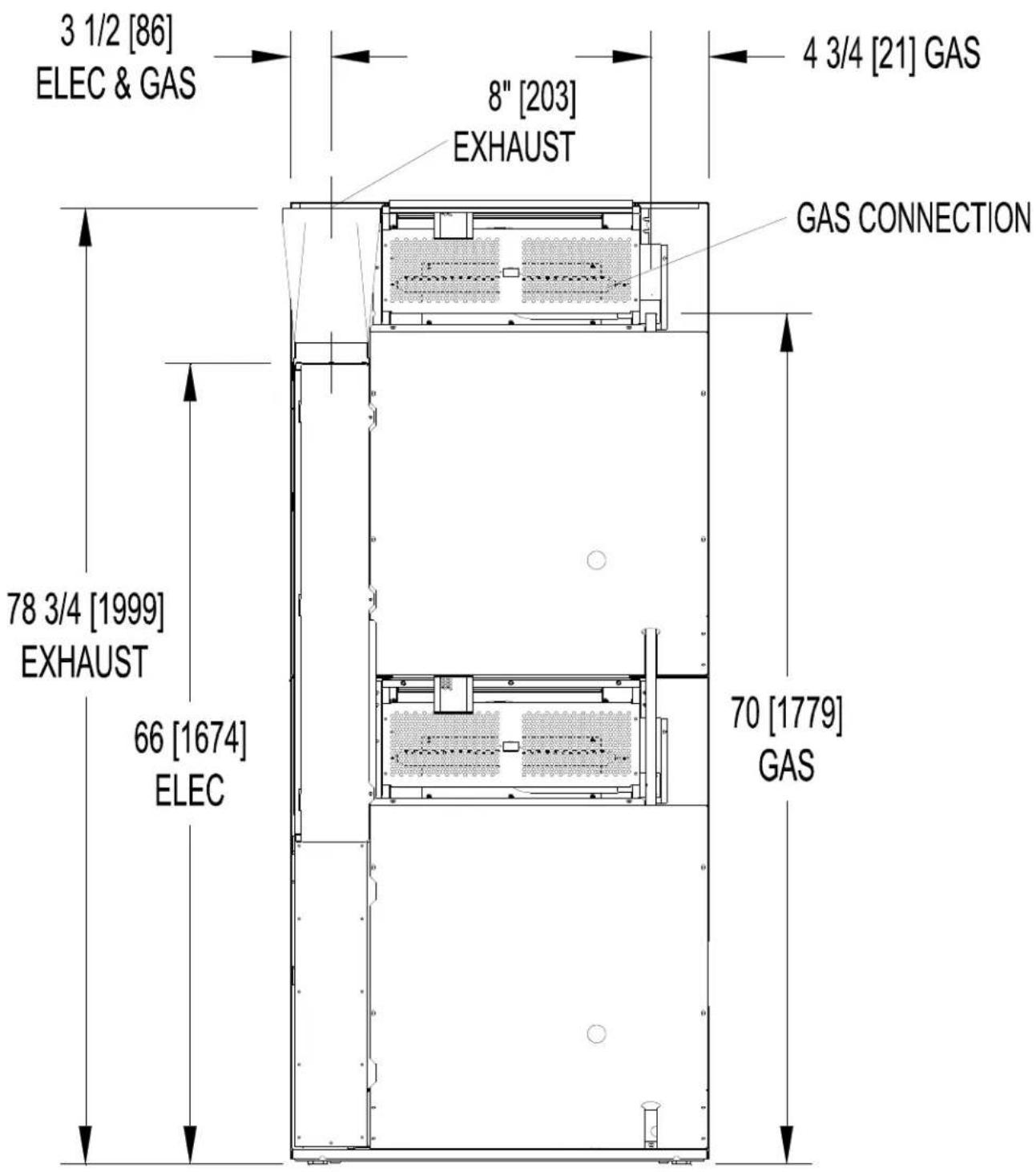
T-50X2 DRYER DIMENSIONS - REAR VIEW
DIMENSIONS ARE IN INCHES [MILLIMETERS]
INSTALLATION INSTRUCTIONS
UNCRATING AND PLACING DRYER
Tools Required: 3 / 4'' (19 mm) hex socket & ratchet driver, wood block 4'' (100 mm) or 5'' (125 mm) thick, a knife and a groove joint pliers, which will open to 13 / 8'' (35 mm).
- Remove and discard packaging.
- The crate base is attached to the dryer by (4) cap screws driven upward from below the crate base. Remove crate base from dryer, by tipping dryer sidewise and place block under crate base rail in center of dryer. Using a ratchet and 3/4'' hex socket, remove and discard (2) crating bolts from side, which is raised. Remove block from under crate base. Repeat for other side. Save the bolts for use if the dryer is ever moved again.
- With a walking motion move dryer completely off crate base. Save the crate base for use if the dryer is ever moved again.
- Slide unit into position where it will be installed. Adjust leveling legs, using the groove joint pliers, to level and align dryer with adjacent units.
Note: If the dryer is ever moved again, the dryer should be re-mounted on its crate base and its crating bolts re-inserted and tightened, in the reverse order as above.
DRYER INSTALLATION
- CODE CONFORMITY: All commercial dryer installations must conform with local codes, or in the absence of local codes, with the latest edition of the National Fuel Gas Code ANSI Z223.1. Canadian installations must comply with the current Standard CAN/CGA-B149 (.1 or .2) Installation Code for Gas Burning Appliances or Equipment, and local codes if applicable. Australian installations must meet installation requirements and pipe sizing requirements of AS/NZA 5601. The appliance, when installed, must be electrically grounded in accordance with the latest edition of the National Electric Code, ANSI/NFPA70, or, when installed in Canada, with Standard CSA C22.1 Canadian Electrical Code Part 1.
- INSTALLATION CLEARANCES: This unit may be installed at the following alcove clearances:
I.LeftSide0"
II. Right Side 0"
III. Back 18" (457 mm) (Certified for 1" (25 mm) clearance; however, 18" (457 mm) clearance is necessary behind the motors to allow servicing and maintenance.)
IV. Front 48" (1220 mm) (to allow use of dryer)
V. Top Refer to figure labeled "Vertical Clearance Dimensions".
AB. Certification allows 0'' clearance for wall framing at the top up to 18'' (456 mm) back from the front.
However, a 1/4'' (6 mm) clearance should be allowed in case the dryer needs moving.
C. A 10'' (250 mm) clearance is required from top at all other points.
VI. Floor This unit may be installed upon a combustible floor.
Do not obstruct the flow of combustion and ventilation air.
Maintain minimum of 1" (25 mm) clearance between duct and combustible material.
Refer to the label attached to the Belt Guard on the rear of the dryer for other installation information and start-up instructions.
- MAKE-UP AIR: Adequate make-up air must be supplied to replace air exhausted by dryers on all types of installations. Refer to specifications for the minimum amount of make-up air opening to outside for each dryer. This is a net requirement of effective area. Screens, grills or louvers, which will restrict the flow of air, must be considered. Consult the supplier to determine the free area equivalent for the grill being used. The source of make-up air should be located sufficiently away from the dryers to allow an even airflow to the air intakes of all dryers. Multiple openings should be provided.
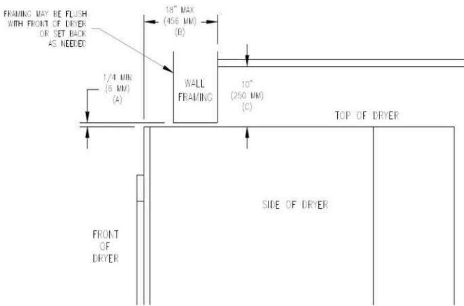
Vertical Clearance Dimensions
The sources of all make-up air and room ventilation air movement to all dryers must be located away from any dry cleaners. This is necessary so that solvent vapors will not be drawn into the dryer inlet ducts. Dry cleaner solvent vapors will decompose in contact with open flame such as the gas flame present in clothes dryers. The decomposition products are highly corrosive and will cause damage to the dryer(s) ducts and clothes loads.
- ELECTRICAL REQUIREMENTS. The electrical power requirements necessary to operate the unit satisfactorily are listed on the serial plate located on the back panel of each dryer and in the specifications section of this manual. The electrical connection should be made to the terminal board, on the rear of the unit. It is absolutely necessary that the dryer be grounded to a known ground. Individual circuit breakers for each stacked dryer are required. Dryer -15 models are adjusted for 120V as shipped. They can be converted to 208-240V as required. Instructions for this conversion are located at this end of this manual.
IMPORTANT: TRANSIENT VOLTAGE SURGE SUPPRESSORS
Like most electrical equipment, your new machine can be damaged or have its life shortened by voltage surges due to lightning strikes which are not covered by factory warranty. Local power distribution problems also can be detrimental to the life of electrical components. We recommend the installation of transient voltage surge suppressors for your new equipment. These devices may be placed at the power supply panel for the complete installation and don't require an individual device for each machine.
These surge protectors help to protect equipment from large spikes and also from small ongoing spikes in the power that occur on a day to day basis. These smaller surges can shorten overall life of electrical components of all types and cause their failure at a later date. Although they can't protect against all events, these protective devices have a good reputation for significantly lengthening the useful life of electronic components. Electronic components are helped to have a longer useful life when they are supplied with the clean stable electrical power they like.
We are including the following names and phone numbers of a few suppliers of these devices for those who don't currently have a source.
MANUFACTURER
CONTACT
PHONE
Innovative Technology, Inc.
Factory
1-800-647-8877 or www.itvss.com
EFI Electronics Corporation
Factory
1-800-877-1174 or wwwefinet.com
Distributor - Surge Pro
1-877-233-0153
MCG Surge Protection
Factory
1-800-851-1508 or www.mcgsurge.com
Advanced Protection Technologies Inc. Factory
1-800-237-4567 or info@apttvss.com
- GAS REQUIREMENTS. The complete gas requirements necessary to operate the dryer satisfactorily are listed on the serial plate located on the back panel of the dryer and in the specifications section of this manual. The inlet gas connection to the unit is 1/2-inch [12.7] pipe thread. However, the size of the piping to supply the dryer should be determined by reference to the National Fuel Gas Code ANSI Z223.1A and consultation with the local gas supplier.
An individual gas shutoff valve is recommended for each dryer and may be required by local code (not supplied).
A joint compound resistant to the action of liquefied petroleum gases should be employed in making pipe connections.
All pipe connections should be checked for leakage with soap solution. Never check with an open flame.
A drip tee should be provided in the gas piping entering the unit to catch dirt and other foreign articles.
A 1/8 inch [3.2] NPT threaded test port, accessible for test gage connection, must be installed immediately upstream of the gas supply connection to the dryer to check the supply pressure. Test and adjust the supply pressure to ensure compliance with the specification listed on the serial plate.
The recommended natural gas supply pressure is 7 inches water column (17.8 cm) at each dryer.
There is a plugged 1/8 inch [3.2] NPT threaded test port in the end of the burner manifold for checking the manifold pressure. With the burner in operation, check and adjust the dryer's gas control valve to ensure compliance with the specification listed on the serial plate for manifold pressure.
After testing, be sure to replace the 1/8 inch [3.2] NPT plugs in the manifold and in the supply line test port using joint compound before operating the dryer.
For altitudes above 2,000 feet (610m), it is necessary to derate the BTU input. Contact your local distributor for instructions.
L.P. gas conversion kits are available for this dryer. Contact your local distributor. CAUTION: The dryer must be disconnected from the gas supply piping system during any pressure testing of that system. Do no expose the dryer's gas control valve to testing pressure.
- EXHAUST INSTALLATION. (Refer to Figure 3) Exhausting of the dryer(s) should be planned and constructed so that no air restrictions occur. Any restriction due to pipe size or type of installation can cause slow drying time, excessive heat, and lint in the room.
From an operational standpoint, incorrect or inadequate exhausting can cause a cycling of the high limit thermostat, which shuts off the main burners and results in inefficient drying.
The exhaust duct connection near the top of the dryer will accept an 8^ (200 mm) round duct. Individual exhausting of the dryers is recommended. All heat, moisture, and lint should be exhausted outside by
attaching a pipe of the proper diameter to the dryer adapter collars and extending it out through an outside wall. This pipe must be very smooth on the inside, as rough surfaces tend to collect lint, which will eventually clog the duct and prevent the dryer from exhausting properly. All elbows must be smooth on the inside. All joints must be made so the exhaust end of one pipe is inside the next one downstream. The addition of an exhaust pipe tends to reduce the amount of air the blower can exhaust. This does not affect the dryer operation if held within practical limits. For the most efficient operation, it is recommended that no more than 14 ft. (4.25 m) of straight 8 in. diameter pipe with two right angle elbows be used for each cylinder.
Maintain a minimum of 1^ (25mm) clearance between duct and combustible material.
If the exhaust pipe passes through a wall, a metal sleeve of slightly larger diameter should be set in the wall and the exhaust pipe passed through this sleeve. This practice is required by some local codes and is recommended in all cases to protect the wall.
This type of installation should have a means provided to prevent rain and high winds from entering the exhaust when the dryer is not in use. A hood with a hinged damper can be used for this purpose. Another method would be to point the outlet end of the pipe downward to prevent entrance of wind and rain. In either case, the outlet should be kept clear, by at least 24 in. (610 mm) of any objects, which would cause air restriction.
Never install a protective screen over the exhaust outlet.
When exhausting a dryer straight up through a roof, the overall length of the duct has the same limits as exhausting through a wall. A rain cap must be placed on top of the exhaust and must be of such a type as to be free from clogging. The type using a cone shaped "roof" over the pipe is suitable for this application.
Exhausting the dryer into a chimney or under a building is not permitted. In either case there is a danger of lint buildup, which can be highly combustible.
Installation of several dryers, where a main discharge duct is necessary, will need the following considerations for installation (see Figure 3). Individual 8^ (200 mm) exhaust ducts from each dryer should enter main discharge duct at a 45-degree angle in the direction of discharge airflow.
NOTE: Never install the individual ducts at a right angle into the main discharge duct. The individual ducts from the dryers can enter at the sides or bottom of the main discharge duct. Figure 3 indicates the various round main duct diameters to use with the individual dryer ducts. The main duct can be rectangular or round, provided adequate airflow is maintained. The total exhausting (main discharge duct plus duct outlet from the dryer) should not exceed the equivalent of 14 ft. (4.25 m) and two elbows. The diameter of the main discharge duct at the last dryer must be maintained to exhaust end.
NOTE: A small diameter duct will restrict airflow; a large diameter duct will reduce air velocity - both contributing to lint build up. An inspection door should be provided for periodic clean out of the main duct.
NOTE: STATIC BACK PRESSURE should be a maximum of 0.3 in. w.c. (7.6 mm w.c.) at the rear exhaust outlet of the dryer. If multiple dryers are connected to the common duct, ensure the back draft damper is installed properly.
DIAMETER TO INCREASE AS SHOWN
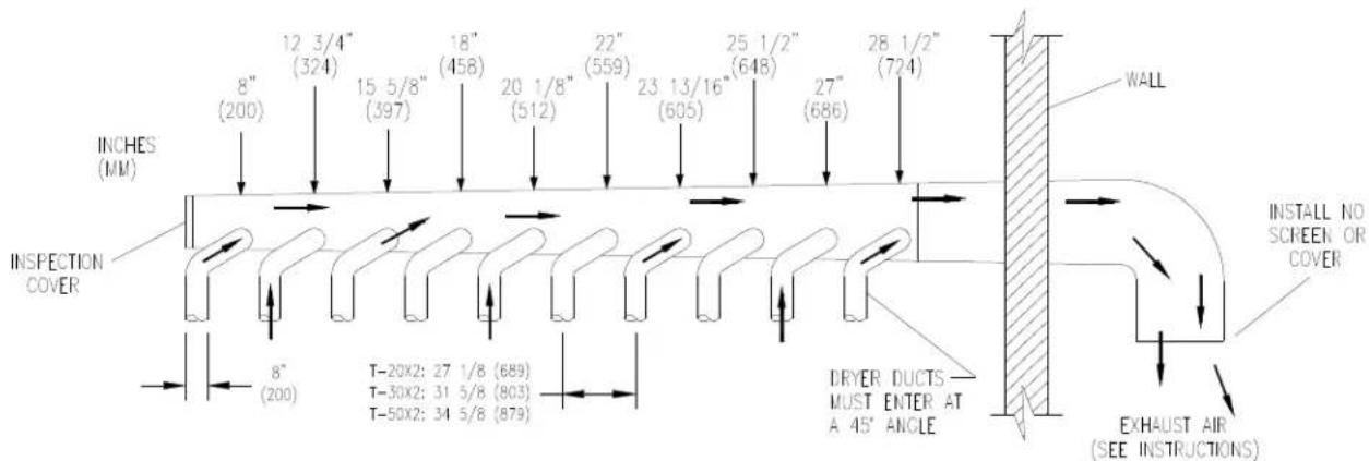
FIGURE 3- Dryer Exhausting Using A Main Discharge Duct
- DRYER IGNITION (SOLID STATE IGNITION): The solid-state ignition system lights the main burner gas by spark. The gas is ignited and burns only when the gas-relay (in the electronic controller) calls for heat. The procedure for first-time starting of a dryer is as follows.
i. First review and comply with the "Warnings About Use and Operation" found on the inside front cover of this manual. Be sure electrical power is connected correctly. The dryer must be properly grounded.
ii. Make sure all gas supply lines are purged of air. Close the main gas shut-off valve and wait for five minutes before turning it back on.
iii. Turn on the main electrical power switch. The dryer may be started by following the "Operating Instructions" found later in this manual.
iv. Natural gas and LPG fired dryers operate in the same manner. When the gas valve relay contacts are closed (indicating a demand for heat), the solid-state ignition control will automatically supply energy to the redundant gas valve. Sparking will continue until a flame is detected by the sensing probe, but not longer than ten seconds. If the gas fails to ignite in 10 seconds, the gas valve closes and the gas system pauses to allow gas to purge from the inside of the dryer. After the pause, the ignition control repeats the ignition trial cycle twice more. If the gas system fails to detect ignition after the three attempts, the system will "lock out". No further attempts will be performed automatically. To reset the ignition control electrical power to the ignition control must be interrupted. This can be done by opening the dryer door (stopping the dryer) for 15 seconds. Closing the door and pushing the "Start" button will repeat the ignition trial cycle.
- MAIN BURNER ADJUSTMENT. The primary air shutter of each main burner must be properly adjusted for the correct air-gas ratio. Loosen the shutter locking screw. Adjust the shutter by closing it sufficiently to give a blue flame with a yellow tip. Next open the shutter until the yellow tips are at a minimum. After adjustment securely lock each shutter in position by tightening the shutter locking screws.
DRYER SHUTDOWN
To render the dryer inoperative, turn off the main gas shut off valve and disconnect the electrical supply to the dryer.
NOTE: The installer must test the dryer for operation and instruct the user before leaving the installation.
DESCRIPTION OF DRYER CONTROL
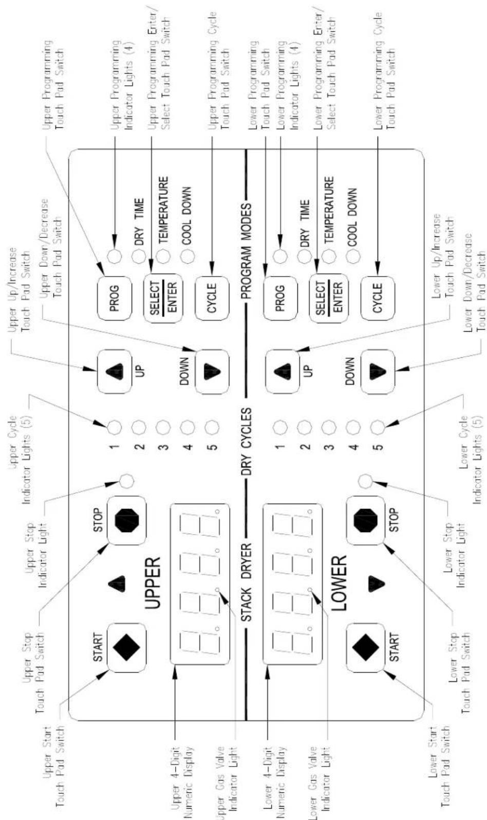
Figure 4: Non-Reversing Dryer Controller Interface
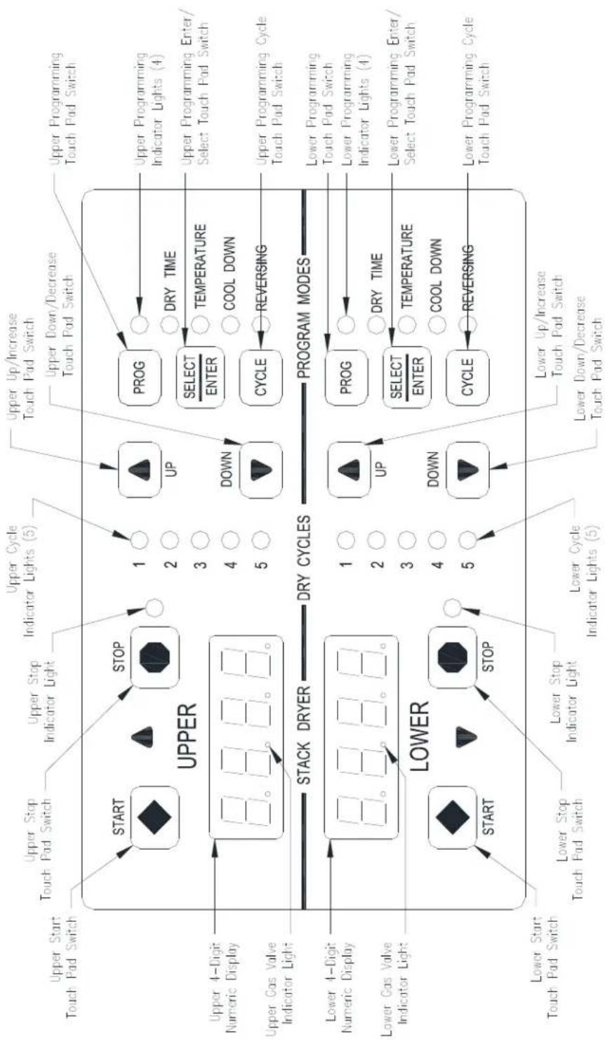
FIGURE 4: REVERSING DRYER CONTROL
DRYER CONTROLLER FACTORY DEFAULT PROGRAM SETTINGS
| DRY CYCLE | COOL DOWN TIME (MINUTES) | TOTAL CYCLE TIME (MINUTES) | DRYING TEMPERATURE (°F) (°C) | DRYER LOAD | |
| 1 | 5 | 35 | 180 | 82 | Towels, pads, heavy cotton |
| 2 | 2 | 20 | 170 | 77 | Sheets, blended materials |
| 3 5 25 180 82 Cotton | |||||
| 4 2 20 130 54 Synthetic materials | |||||
| 5 2 25 175 79 Blended materials | |||||
DRYER FAULT CODES
| FAULT # | FAULT DESCRIPTION | ACTION |
| F1 | Shorted thermostat sensor. | Dryer stops and "F1" flashes on the 4-digit display. When short circuit on sensor input is removed, "LOAd" appears on the 4-digit display and the remaining dry time is reset. |
| F2 | Open thermostat sensor. | Dryer stops and "F2" flashes on the 4-digit display. When a good sensor is connected to sensor input, "LOAd" appears on the 4-digit display and the remaining dry time is reset. |
| F3 | EEPROM corrupted. | Dryer will not start and "F3" appears on the 4-digit display. The power to the dryer must be cycled to reset the controller. Fault should only occur when starting a dry cycle. |
| F4 | Gas valve on fault. | The drying temperature did not increase 1°F. in 15 minutes. "F4" will flash on the display and the dry cycle will finish without calling for heat (energizing gas valve). Opening the door or pressing the STOP key will reset the fault and clear the remaining time in the dry cycle. |
| F5 | Temperature fault. | The drying temperature is at least 25°F. above the temperature setting. "F5" will flash on the 4-digit display and the dry cycle will finish without calling for heat (energizing the gas valve). The power to the dryer must be cycled to reset the controller. |
TOUCH PAD DESCRIPTION
INDICATOR LIGHTS (L.E.D.s)
Description
Cycle (1 through 5) These L.E.D.s are on solid when a particular cycle is chosen for operation or programming.
Gas Valve This L.E.D. is part of the 4-digit numeric display and will be on solid during the drying part of a cycle when the gas valve does not need to be on. The L.E.D. will be blinking when the gas valve needs to be on. The L.E.D. will not be on solid or blinking (off) if the cycle is stopped, complete, in cool down, or terminated.
Programming These L.E.D.s are on solid as they are selected during the programming of the dryer controller.
Stop This L.E.D. is on solid when either the STOP button is pressed once or the door is opened during an operating cycle.
SWITCHES (Pushbuttons)
Description

UP
touch pad switch will
I increment (increase) dry time,
cool down time, and drying temperature. It will also scroll upwards when selecting a dry cycle.
Up/Increase

DOWN
Down/Decrease

His touch pad switch allows the dryer controller to enter the
permanent programming mode.
Program

Select/Enter cycle program.
This touch pad switch will select one of the three variable parts of the dry cycle (dry time, temperature, or cool down) by sequencing through them. Once one of the variable parts of the dry cycle is chosen and changed, this touch pad switch will enter the new (changed) value into the dry
SWITCHES (Pushbuttons) - continued
Description

is touch pad switch allows the dryer controller to enter the
temporary programming mode.
Cycle

STOP
This touch pad switch will stop the dryer during a dry cycle without clearing the present drying cycle if pressed once. If pressed and released twice, consecutively, the present dry cycle will be cleared.
Stop

START
This touch pad switch will start the operation of a dry cycle if pressed and released once. Pressing and holding this touch pad switch will display the current temperature of the dryer heat sensor as long as it is held in the depressed position.
Start
4-DIGIT NUMERICAL DISPLAY MESSAGES
Message Description
LOAd This message is displayed after a dry cycle is complete and the dryer loading door has been opened or the STOP touch pad key on the dryer controller has been pressed and released twice.
donE This message blinks immediately after completion of the dry cycle and continues to blink until the stop key on the dryer controller touch pad is pressed or the dryer loading door is opened.
Prog This message is displayed when entering the permanent programming mode.
.15 This message appears while the dryer is in the heating time of a dry cycle. The decimal point will blink if the output for the gas valve is on, or remain on constantly if the output for the gas valve is not on. The number represents the total time left in the dry cycle (includes cool down time).
C02 This message appears when the cool down time of the dry cycle is reached. The letter "C" represents the cool down (non-heating) part of the dry cycle. The number(s) after the letter "C" represent(s) the total time remaining in the dry cycle.
F5 This message appears if there is a dryer fault. The letter "F" indicates a fault and the number after the "F" represents the specific fault that has occurred. There are five different faults that can appear (F1 through F5).
OPERATING INSTRUCTIONS
To dry a load of items, you must choose one of the five-programmed dry cycles. Each of these five dry cycles may be modified in two different ways to match your load. Please refer to the "Permanent Dryer Controller Programming" or "Temporary Dryer Controller Programming" section of this manual.
There are two parts to each dry cycle. The first part is the heating time, which is when the gas valve is cycled on and off according to the temperature setting in the dry cycle program. The second part is the cool down time, which is after the heating part of the dry cycle, and is when the cylinder continues to turn, but no heat is applied.
There will always be at least two minutes of cool down time for each dry cycle. The maximum amount of cool down time is 60 minutes.
During a reversing dry cycle, the tumbler will rotate in one direction for one minute, decelerate for four seconds, and then rotate in the opposite direction for one minute. This motion will repeat for the duration of the dry cycle. To change the reversing time, the 4-digit numerical display must show "LOAd". Then, press and hold the SELECT/ENTER touch pad switch and then press the UP touch pad switch to set the time to two minutes or the DOWN touch pad switch to set the time to one minute. The buzzer will then beep to indicate the change was successful. The change will be retained even if the power is removed. The factory default is one minute.
The default value of the five dry cycles is shown in the "DRYER CONTROLLER FACTORY DEFAULT PROGRAM SETTINGS" table in this manual.
To improve the drying capabilities of this dryer, you should always separate (untangle) the individual articles in your load before using the dryer.
In the following instruction steps, things that are displayed on the 4-digit numerical display will be in "quotation marks" and any keys on the dryer controller touch pad that physically need to be pressed will be in CAPITAL AND BOLD LETTERS.
1) Place your untangled load into the dryer cylinder and close the dryer loading door. Notice that the dryer controller 4-digit numerical display should show the word "LOAd". If it does not show this word, then press and release the STOP touch pad key on the dryer controller twice.
2) Press and release the UP or DOWN arrow touch pad key on the dryer controller to select a dry cycle.
3) Once the desired dry cycle is selected, press and release the START touch pad key.
After the dryer controller START touch pad key is pressed, the dryer cylinder will start rotating and the two-digit total dry cycle time, along with a decimal point, will appear on the dryer controller display.
The time shown on the dryer controller display will count down to the programmed cool down time. At that time, the display will change from the decimal point and two-digit number to a letter "C" and two digits.
The letter "C" represents the cool down portion of the dry cycle. The two digits represent the amount of time remaining in the dry cycle. The two-digit time, shown on the dryer controller display, will count down to zero.
When the time decrements to zero, the dryer controller display will flash the word "donE" and the end of cycle tone will sound.
At that point, the wrinkle free cycle will automatically begin. This cycle will wait two minutes, if the door is not opened or the STOP touch pad key on the dryer controller is not pressed, and then rotate the cylinder for 10 seconds and stop. This idle time of two minutes and tumble time of 10 seconds will repeat a total of 10 times, at which time the wrinkle free cycle stops. The cylinder will not rotate again until a new dry cycle is started.
During the wrinkle free cycle the gas valve will not be operated and there will be no heat applied to the load. The word "donE" will also continue to flash and do so even after the wrinkle free cycle is finished. When the dryer loading door is opened, or the STOP touch pad key is pressed, the word "donE" will change to the word "LOAd" on the dryer controller display. The dryer will then be ready for another dry cycle.
During the dry cycle, either pressing the STOP touch pad key on the dryer controller or opening the dryer loading door, will stop the dry cycle and not clear it. If you press the STOP touch pad key on the controller and then open the dryer loading door the dry cycle will not be cleared. However, if you open (or open and close) the dryer loading door and then press the STOP touch pad key on the dryer controller, the present dry cycle will be cleared and the word "LOAd" will appear on the dryer controller display.
There are two jumpers and one push button on the component side of the dryer controller printed circuit board.
The jumper located at the back right side of the each circuit board controls whether the controller display shows and operates in the Fahrenheit or Celsius mode. This jumper is labeled as TEMP SELECT and has three pins. The back and middle pins are for Celsius and the front and middle pins are for Fahrenheit, which is indicated by the letter C for Celsius and the letter F for Fahrenheit.
Non-reversing:
The other jumper, located at the back middle side of each circuit board controls, is used for choosing either a reversing or non-reversing type of dryer. This jumper is labeled as REV and NON-REV. This jumper must be in the non-reversing position, which are the front and middle pins. If the jumper is in the reversing position, the heating part of the dry cycle will not operate properly. The dryer will not reverse direction either.
Reversing:
The other jumper, located at the back middle side of each circuit board controls, is used for choosing either a reversing or non-reversing type of dryer. This jumper is labeled as REV and NON-REV. This jumper must be in the reversing position, which are the middle and rear pins.
The push button, which is located at the middle center of each circuit board controls, is used to reset all five of the dry cycles to the factory default settings. It is labeled as DEFAULT SETTINGS. Even the dry cycles that have been modified using the permanent programming procedure will be changed back to the factory default settings when using this push button. This push button must be pressed and held for at least three seconds with power applied to the dryer controller circuit board.
If changing a jumper, remove power before moving jumper and then move jumper. Before restoring power, press and hold the DEFAULT SETTINGS pushbutton. Then, restore power and release the DEFAULT SETTINGS pushbutton after three seconds of restoring power.
TEMPORARY NON-REVERSING DRYER CONTROLLER PROGRAMMING
The temporary programming mode will allow the change of the stored dry cycle settings in the dryer controller for one complete dry cycle. After the dry cycle is complete, the default settings that existed before the temporary change are restored. The temporary dry cycle can be stopped and cleared at any time during the dry cycle operation.
To temporarily change a dryer controller cycle, follow the procedures below. Things that are displayed on the 4-digit numeric display will be in "quotation marks". Keys on the dryer controller touch pad that physically need to be pressed will be in CAPITAL AND BOLD LETTERS.
If, at any time, you want to escape the temporary programming mode while changing the program settings, you can press the STOP key on the dryer controller touch pad if the 4-digit numeric display is not flashing. The SELECT/ENTER key on the dryer controller touch pad can be pressed and released to enter the flashing value shown on the 4-digit numeric display and allow you to escape.
If you press and release the STOP key on the dryer controller touch pad, when the 4-digit numeric display is not flashing, the temporary changes to the dry cycle program will be cancelled. The stored dry cycle settings that existed before the temporary change will then be restored.
If, at any time, you want to start the temporary dry cycle during the temporary programming mode, press and release the START key on the dryer controller touch pad if the 4-digit numeric display is not flashing. The SELECT/ENTER key on the dryer controller touch pad can be pressed and released to enter the flashing value shown on the 4-digit numeric display and allow you to start the temporary dry cycle. If you start the temporary dry cycle, the 4-digit numerical display will change to the total dry time and count down to 0 as the dry cycle progresses.
PROCEDURE
1) Make sure the dryer is not in a dry cycle. The 4-digit numeric display on the dryer controller will show "LOAd" when the dryer is not in a dry cycle.
2) Press and release the UP or DOWN arrow keys on the dryer controller touch pad to chose the dry cycle that you want to change (dry cycle 1 through 5). The dry cycle L.E.D. will illuminate to indicate which dry cycle you are choosing. If you press either arrow key and hold it down, the controller will sequence through the five dry cycles.
3) Press and release the CYCLE key on the dryer controller touch pad once you have chosen the dry cycle you want to change. After you press this key, the programming L.E.D. and the dry time L.E.D. will illuminate. The dry cycle L.E.D. will remain illuminated. The total dry time will also be displayed on the 4-digit numeric display.
4) Press and release the UP or DOWN arrow keys to change the total cycle time. Once either of the arrow keys is pressed, the dry time L.E.D. and the total dry time on the 4-digit numeric display will flash. If you press and hold either arrow key down, you will increment (UP arrow) or decrement (DOWN arrow) through the total dry times available (1 through 60 minutes). This displayed dry time includes the cool down time along with the heated time. To not change the total dry time, do not press the arrow keys to change the total dry time.
5) Press and release the SELECT/ENTER key. Once this key is pressed and released, the dry time L.E.D. will switch off, the dry cycle L.E.D. and programming L.E.D. will remain on, and the temperature L.E.D. will illuminate. The drying temperature will also be shown on the 4-digit numeric display.
6) Press and release the UP or DOWN arrow keys to change the drying temperature. Each press and release of the arrow keys will either increase or decrease the temperature by five degrees Fahrenheit or three degrees Celsius, depending on how your dryer controller is set up. Once either of the arrow keys is pressed, the temperature L.E.D. and the drying temperature on the 4-digit numeric display will flash. If you press and hold either arrow key down, you will increment (UP arrow) or decrement (DOWN arrow) your way through the available drying temperatures (105^ Fahrenheit or 40^ Celsius, up to 195^ Fahrenheit or 91^ Celsius). If you do not want to change the drying temperature, do not press the arrow keys. Go to the next step.
7) Press and release the SELECT/ENTER key. Once this key is pressed and released, the temperature L.E.D. will switch off, the dry cycle L.E.D. and programming L.E.D. will remain on, and the cool down L.E.D. will illuminate. The cool down time will also be shown on the 4-digit numeric display.
8) Press and release the UP or DOWN arrow keys to change the cool down time. Once either of the arrow keys is pressed, the cool down L.E.D. and the cool down time on the 4-digit numeric display will flash. If you press and hold either arrow key down, you will increment (UP arrow) or decrement (DOWN arrow) through the cool down times available (2 through 60 minutes). To not change the cool down time, do not press the arrow keys. Go to the next step.
9) Press and release the SELECT/ENTER key. Once this key is pressed and released, the cool down L.E.D. and the programming L.E.D. will switch off, and the dry cycle L.E.D. will remain on. The flashing cool down time on the 4-digit display will stop flashing and remain.
10) At this point, you have two choices. 1) You can perform the modified dry cycle by pressing and releasing the START key on the dryer controller touch pad, or 2) You can clear the modified dry cycle program by pressing and releasing the STOP key once. If you start the modified cycle, the total dry time will appear on the 4-digit numeric display and it will count down to 0 as the dry cycle progresses. If you choose to clear the modified dry cycle, the 4-digit numeric display will change to "LOAd".
TEMPORARY NON-REVERSING DRYER CONTROLLER PROGRAMMING EXAMPLE
REQUIREMENTS: Dry a load with 40 minutes of actual heat at 185^ and five minutes of cool down.
The following procedure will show you how to temporarily modify the existing dry cycle 1 program for one cycle of drying. It is based on the assumption that the factory defaults have not been permanently changed. If they have been changed, the steps of this procedure will be the same, but the values that are displayed will be different. The amount of times that the dryer controller touch pad UP or DOWN keys must be pressed and released may also be different.
If you want the change to be permanent, go to the "PERMANENT DRYER CONTROLLER PROGRAMMING" section of this manual.
PROCEDURE
1) After the load has been placed in the dryer, press and release the UP or DOWN touch pad key on the dryer controller until the L.E.D. for dry cycle 1 is illuminated.
2) Press and release the CYCLE key on the dryer controller touch pad. You will see the number "35" on the dryer controller display. The programming L.E.D. and dry time L.E.D. will be illuminated.
3) Press and release the UP arrow key on the dryer controller touch pad 10 times so the display will show a flashing "45". When the UP arrow touch pad key is pressed the first time, the number "36" will be flashing on the dryer controller display. Each number after that will also flash.
4) Now, press and release the SELECT/ENTER touch pad key on the dryer controller. The number "45" will stop flashing and the dry time L.E.D. will switch off. The dryer controller display will now show "180", the temperature L.E.D. will illuminate, and the programming L.E.D. and dry cycle 1 L.E.D. will remain on.
5) Press and release the UP arrow key on the dryer controller touch pad one time so the controller display will show a flashing "185". Each press of the UP arrow key will increment the temperature by five degrees.
6) Now, press and release the SELECT/ENTER touch pad key on the dryer controller. The number "185" will stop flashing and the temperature L.E.D. will switch off. The dryer control display will now show a number "5", the cool down L.E.D. will illuminate, and the programming L.E.D. and dry cycle 1 L.E.D. will remain on.
7) Press and release the SELECT/ENTER key on the dryer controller touch pad, since the desired cool down time is five minutes. After you press the SELECT/ENTER touch pad key on the controller, the cool down L.E.D. and programming L.E.D. will switch off. The controller display will remain at "5" and the cycle 1 L.E.D. will remain on.
You are now ready to start the new dry cycle. This new dry cycle will be in effect for one dry cycle only. After the dry cycle is done, or if the STOP touch pad key on the dryer controller is pressed and released twice, consecutively, the cycle 1 program will revert to the factory default settings.
If you press the START touch pad key on the dryer controller, the controller display will change from the number "5" to the number "45" and dry cycle 1 will begin.
PERMANENT NON-REVERSING DRYER CONTROLLER PROGRAMMING
The permanent programming mode will allow the change of the stored dry cycle settings in the dryer controller until the operator physically changes them again. The factory default settings can be restored in the dryer controller by pressing the default settings pushbutton on the back (component) side of the dryer controller circuit board. It is labeled and located at the lower middle side of the printed circuit board, as you face the component side of the board. It must be pressed and held down for at least three seconds.
To permanently change a dryer controller cycle, follow the procedure below. Things that are displayed on the 4-digit numeric display will be in "quotation marks". Keys on the touch pad that physically need to be pressed will be in CAPITAL AND BOLD LETTERS.
If, at any time, you want to escape the permanent programming mode while changing the settings, you can press the STOP key on the dryer controller touch pad if the 4-digit numeric display is not flashing. The SELECT/ENTER key on the dryer controller touch pad can be pressed and released to enter the flashing value shown on the 4-digit numeric display and allow you to escape.
PROCEDURE
1) Make sure the dryer is not in a dry cycle. The 4-digit numeric display on the dryer controller will show "LOAd" when the dryer is not in a dry cycle.
2) Press and release the PROG key on the dryer controller touch pad.
3) Press and release the UP arrow key on the dryer controller touch pad. The programming L.E.D. will illuminate and the 4-digit numeric display on the dryer controller will change to "Prog".
4) Press and release the UP or DOWN arrow keys to choose the dry cycle you want to change (dry cycle 1 through 5). The dry cycle L.E.D. will illuminate to indicate which dry cycle you are choosing. If you press either arrow key and hold it down, the controller will sequence through the five dry cycles.
5) Press and release the SELECT/ENTER key once you have chosen the dry cycle you want to change. After you press this key, the dry time L.E.D. will illuminate. The dry cycle L.E.D. and the programming L.E.D. will remain illuminated. The total dry time will also be displayed on the 4-digit numeric display.
6) Press and release the UP or DOWN arrow keys to change the total dry time. Once either of the arrow keys is pressed, the dry time L.E.D. and the total dry time on the 4-digit numeric display will flash. If you press and hold either arrow key down, you will increment (UP arrow) or decrement (DOWN arrow) through the total dry times available (1 through 60 minutes). This displayed dry time includes the cool down time along with the heated time. To not change the total dry time, do not press the arrow keys. Go to the next step.
7) Press and release the SELECT/ENTER key. Once this key is pressed and released, the dry time L.E.D. will switch off, the dry cycle L.E.D. and programming L.E.D. will remain on, and the temperature L.E.D. will illuminate. The drying temperature will also be shown on the 4-digit numeric display.
8) Press and release the UP or DOWN arrow keys to change the drying temperature. Each press and release of the arrow keys will either increase or decrease the temperature by five degrees Fahrenheit or three degrees Celsius, depending on how your dryer controller is set up. Once either of the arrow keys is pressed, the temperature L.E.D. and the drying temperature on the 4-digit numeric display will flash. If you press and hold either arrow key down, you will increment (UP arrow) or decrement (DOWN arrow) your way through the available drying temperatures (105° Fahrenheit or 40° Celsius, up to 195° Fahrenheit or 91° Celsius). If you do not want to change the drying temperature, do not press the arrow keys. Go to the next step.
9) Press and release the SELECT/ENTER key. Once this key is pressed and released, the temperature L.E.D. will switch off, the dry cycle L.E.D. and programming L.E.D. will remain on, and the cool down L.E.D. will illuminate. The cool down time will also be shown on the 4-digit numeric display.
10) Press and release the UP or DOWN arrow keys to change the cool down time. Once either of the arrow keys is pressed, the cool down L.E.D. and the cool down time on the 4-digit numeric display will flash. If you press and hold either arrow key down, you will increment (UP arrow) or decrement (DOWN arrow) through the cool down times available (2 through 60 minutes). To not change the cool down time, do not press the arrow keys. Go to the next step.
11) Press and release the SELECT/ENTER key. Once this key is pressed and released, the cool down L.E.D. will switch off, the dry cycle L.E.D. and programming L.E.D. will remain on, and the 4-digit numeric display will change to "Prog".
12) Press and release the STOP key to save the cycle program and escape the programming mode. If you want 8514-259-001 REV L PAGE 31
to change the same dry cycle program again, press the SELECT/ENTER key and continue at step 6 of this procedure. If you want to modify another dry cycle program, go to step 4 of this procedure and continue.
13) If you pressed the STOP key to escape the programming mode, you may now start the dry cycle by pressing the START key.
PERMANENT NON-REVERSING DRYER CONTROLLER PROGRAMMING EXAMPLE
REQUIREMENTS: Dry a load with 50 minutes of actual heat at 195^ F and three minutes of cool down.
The following procedure will show you how to permanently modify the existing dry cycle 1 program for one cycle of drying. It is based on the assumption that the factory defaults have not been permanently changed. If they have been changed, the steps of this procedure will be the same, but the values that are displayed will be different. The amount of times that the dryer controller touch pad UP or DOWN keys must be pressed and released may also be different.
If you want the change to be temporary (for only one dry cycle), go to the "TEMPORARY DRYER CONTROLLER PROGRAMMING" section of this manual.
PROCEDURE
1) After the load has been placed in the dryer, press and release the UP or DOWN touch pad key on the dryer controller until the L.E.D. for dry cycle 1 is illuminated.
2) Press and release the PROG touch pad key on the dryer controller. The dryer controller display will not change.
3) Immediately, press and release the UP arrow key on the dryer controller touch pad. The controller display will change from "LOAd" to "Prog". You have now entered the permanent programming mode. The dry time L.E.D. will remain on and the programming L.E.D. will illuminate.
4) Press and release the SELECT/ENTER touch pad key once. The dry time L.E.D. and programming L.E.D. will remain on and the dry time L.E.D. will illuminate. The dryer controller will also show the number "35".
5) Press the UP arrow touch pad key 18 times until the dryer controller display shows the number "53".
6) Press and release the SELECT/ENTER touch pad key once. The dry time L.E.D. and programming L.E.D. will remain on and the dry time L.E.D. will switch off. The temperature L.E.D. will illuminate and the dryer controller display will show the number "180".
7) Press and release the UP arrow touch pad key three times until the dryer controller display shows the number "195".
8) Press and release the SELECT/ENTER touch pad key. The dry time L.E.D. and the programming L.E.D. will remain on and the temperature L.E.D. will switch off. The cool down L.E.D. will illuminate and the dryer controller display will show the number "5".
9) Press and release the DOWN arrow touch pad key twice until the dryer controller display shows the number "3".
10) Press and release the SELECT/ENTER touch pad key. The dry time L.E.D. and the programming L.E.D. will remain on and the cool down L.E.D. will switch off. The dryer controller display will change to "Prog".
11) Press and release the STOP touch pad key. The dry time L.E.D. will remain on and the programming L.E.D. will switch off. The dryer controller display will change to the word "LOAd".
The dryer is now ready for the new modified dry cycle to start. This modified dry cycle 1 program will remain in the dryer controller memory until the default settings push button is pressed. This default settings push button is located on the component side of the dryer controller printed circuit board at the middle center side of each circuit board controls.
TEMPORARY REVERSING DRYER CONTROLLER PROGRAMMING
The temporary programming mode will allow the change of the stored dry cycle settings in the dryer controller for one complete dry cycle. After the dry cycle is complete, the default settings that existed before the temporary change are restored. The temporary dry cycle can be stopped and cleared at any time during the dry cycle operation.
To temporarily change a dryer controller cycle, follow the procedures below. Things that are displayed on the 4-digit numeric display will be in "quotation marks". Keys on the dryer controller touch pad that physically need to be pressed will be in CAPITAL AND BOLD LETTERS.
If, at any time, you want to escape the temporary programming mode while changing the program settings, you can press the STOP key on the dryer controller touch pad if the 4-digit numeric display is not flashing. The SELECT/ENTER key on the dryer controller touch pad can be pressed and released to enter the flashing value shown on the 4-digit numeric display and allow you to escape.
If you press and release the STOP key on the dryer controller touch pad, when the 4-digit numeric display is not flashing, the temporary changes to the dry cycle program will be cancelled. The stored dry cycle settings that existed before the temporary change will then be restored.
If, at any time, you want to start the temporary dry cycle during the temporary programming mode, press and release the START key on the dryer controller touch pad if the 4-digit numeric display is not flashing. The
SELECT/ENTER key on the dryer controller touch pad can be pressed and released to enter the flashing value shown on the 4-digit numeric display and allow you to start the temporary dry cycle. If you start the temporary dry cycle, the 4-digit numerical display will change to the total dry time and count down to 0 as the dry cycle progresses.
PROCEDURE
1) Make sure the dryer is not in a dry cycle. The 4-digit numeric display on the dryer controller will show "LOAd" when the dryer is not in a dry cycle.
2) Press and release either the UP or DOWN touch pad switch on the dryer controller to choose the dry cycle that you want to change (dry cycle 1 through 5). The dry cycle L.E.D. will illuminate to indicate which dry cycle you are choosing. If you press and hold down either the UP or DOWN touch pad switch, the controller will sequence through the five dry cycles.
3) Press and release the CYCLE touch pad switch on the dryer controller once you have chosen the dry cycle you want to change. After you press the CYCLE touch pad switch, the programming L.E.D. and the dry time L.E.D. will illuminate, the dry cycle L.E.D. will remain illuminated, and the total dry time will be displayed on the 4-digit numeric display.
4) Press and release either the UP or DOWN touch pad switch on the dryer controller to change the total cycle time. Once either the UP or Down touch pad switch is pressed, the dry time L.E.D. and the total dry time on the 4-digit numeric display will flash. If you press and hold down either UP or DOWN touch pad switch, you will increment (UP arrow) or decrement (DOWN arrow) through the total dry times available (1 through 60 minutes). This display dry time includes the cool down time along with the heated time. To not change the cool down time, do not press either the UP or DOWN touch pad switch. Go to the next step.
5) Press and release the SELECT/ENTER touch pad switch on the dryer controller. Once the SELECT/ENTER touch pad switch is pressed and released, the dry time L.E.D. will switch off, the dry cycle L.E.D. and programming L.E.D. will remain on, the temperature L.E.D. will illuminate, and the drying temperature will be shown on the 4-digit numeric display.
6) Press and release either the UP or DOWN touch pad switch on the dryer controller to change the drying temperature. Each press and release of either the UP or DOWN touch pad switch will either increase or decrease, respectively, the temperature by five degrees Fahrenheit or three degrees Celsius, depending on how your dryer controller is set up. Once either the UP or DOWN touch pad switch is pressed, the temperature L.E.D. and the drying temperature on the 4-digit numeric display will flash. If you press and hold down either the UP or DOWN touch pad switch, you will increment (UP arrow) or decrement (DOWN arrow) your way through the available drying temperatures (105^ Fahrenheit or 41^ Celsius, up to 195^ Fahrenheit or 90^
Celsius). If you do not want to change the drying temperature, do not press either the UP or DOWN touch pad switch. Go to the next step
7) Press and release the SELECT/ENTER touch pad switch on the dryer controller. Once the SELECT/ENTER touch pad switch is pressed and released, the temperature L.E.D. will switch off, the dry cycle L.E.D. and programming L.E.D. will remain on, the cool down L.E.D. will illuminate, and the cool down time will be shown on the 4-digit numeric display.
8) Press and release either the UP or DOWN touch pad switch on the dryer controller to change the cool down time. Once either the UP or DOWN touch pad switch is pressed, the cool down time L.E.D. and the cool down time on the 4-digit numeric display will flash. If you press and hold down either the UP or DOWN touch pad switch, you will increment (UP arrow) or decrement (DOWN arrow) through the cool down times available (2 through 60 minutes if the controller has a red dot sticker or 2 through 15 minutes if the controller has no red dot sticker). To not change the cool down time, do not press either the UP or DOWN touch pad switch. Go to the next step.
9) Press and release the SELECT/ENTER touch pad switch on the dryer controller. Once the SELECT/ENTER touch pad switch is pressed and released, the cool down L.E.D. will switch off, the dry cycle L.E.D. and the programming L.E.D. will remain on, the reversing L.E.D. will illuminate, and either "rEv" (reversing mode) or "nrEv" (non-reversing mode) will be shown on the 4-digit numeric display.
10) Press and release either the UP or DOWN touch pad switch to change between reversing and non-reversing operation. Once either the UP or DOWN touch pad switch is pressed, the reversing L.E.D. and the "rEv" (reversing mode) or the "nrEv" (non-reversing mode) shown on the 4-digit numeric display will flash. To not change the reversing or non-reversing mode of operation, do not press either the UP or DOWN touch pad switch. Go to the next step.
11) Press and release the SELECT/ENTER touch pad switch on the dryer controller. Once the SELECT/ENTER touch pad switch is pressed and released, the programming L.E.D. will switch off, the reversing L.E.D. and the dry cycle L.E.D. will remain on, and the flashing reversing (rEv) or the non-reversing (nrEv) on the 4-digit numeric display will stop flashing and remain.
12) At this point, you have two choices:
a) You can perform the modified dry cycle by pressing and releasing the START touch pad switch on the dryer controller touch pad. If you start the modified cycle, the total dry time will appear on the 4-digit numeric display and it will count down to 0 as the dry cycle progresses.
b) You can clear the modified dry cycle program by pressing and releasing the STOP touch pad switch. If you choose to clear the modified dry cycle, the 4-digit numeric display will change to "LOAd".
TEMPORARY DRYER CONTROLLER PROGRAMMING EXAMPLE
REQUIREMENTS: Dry a load, in reverse mode, with 40 minutes of actual heat at 185^ and two minutes of cool down.
The following procedure will show you how to temporarily modify the existing dry cycle 5 program for one cycle of drying. It is based on the assumption that the factory defaults have not been permanently changed. If they have been changed, the steps of this procedure will be the same, but the values that are displayed will be different. The amount of times that the UP or DOWN touch pad switches of the dryer controller must be pressed and released may also be different.
If you want the change to be permanent, go to the "PERMANENT REVERSING DRYER CONTROLLER PROGRAMMING" section of this manual.
PROCEDURE
1) After the load has been placed in the dryer, press and release either the UP or DOWN touch pad switch on the dryer controller until the L.E.D. for dry cycle 5 is illuminated.
2) Press and release the CYCLE touch pad switch on the dryer controller. You will see the number "25" on the dryer controller display. The programming L.E.D. and dry time L.E.D. will be illuminated.
3) Press and release the UP touch pad switch on the dryer controller 17 times so that the display will show a flashing "42". When the UP touch pad switch is pressed the first time, the number "26" will be flashing on the dryer controller display. Each number after that will also flash.
4) Now, press and release the SELECT/ENTER touch pad switch on the dryer controller. The number "42" will stop flashing, the dry time L.E.D. will switch off, the dryer controller display will now show "175", the temperature L.E.D. will illuminate, and the programming L.E.D. and dry cycle 5 L.E.D. will remain on.
5) Press and release the UP touch pad switch on the dryer controller two times so the controller display will show a flashing "185". Each press of the UP touch pad switch will increment the temperature by five degrees.
6) Now, press and release the SELECT/ENTER touch pad switch on the dryer controller. The number "185" will stop flashing, the temperature L.E.D. will switch off, the dryer control display will now show a number "2", the cool down L.E.D. will illuminate, and the programming L.E.D. and dry cycle 5 L.E.D. will remain on.
7) Press and release the SELECT/ENTER touch pad switch on the dryer controller, since the desired cool down time is two minutes. After you press the SELECT/ENTER touch pad switch, the cool down L.E.D. will switch off, the dryer controller display will show "nrEv", the reversing L.E.D. will illuminate, and the programming L.E.D. and the cycle 5 L.E.D. will remain on.
8) Press and release either the UP or DOWN touch pad switch on the dryer controller once. A flashing "rEv" will appear on the dryer controller display and the reversing L.E.D will start to flash. Each press and release of either the UP or DOWN touch pad switch will toggle between the reversing mode ("rEv") and the non-reversing mode ("nrEv").
9) Press and release the SELECT/ENTER touch pad switch on the dryer controller. Once the SELECT/ENTER touch pad switch is pressed and released, the programming L.E.D. and the reversing L.E.D. will switch off, the dry cycle 5 L.E.D. will remain on, and the flashing "rEv" will stop flashing and remain on.
You are now ready to start the new dry cycle. This new dry cycle will be in effect for one dry cycle only. After the dry cycle is done, or if the STOP touch pad switch on the dryer controller is pressed and released twice, consecutively, the cycle 5 program will revert to the factory default settings.
If you press the START touch pad switch on the dryer controller, the controller display will change from the "rEv" to the number "42" and dry cycle 5 will begin.
PERMANENT REVERSING DRYER CONTROLLER PROGRAMMING
The permanent programming mode will allow the change of the stored dry cycle settings in the dryer controller until the operator physically changes them again. The factory default settings can be restored in the dryer controller by pressing the default settings pushbutton on the back (component) side of the dryer controller circuit board. It is labeled and located at the lower middle side of the printed circuit board, as you face the component side of the board. It must be pressed and held down for at least three seconds.
To permanently change a dryer controller cycle, follow the procedure below. Things that are displayed on the 4-digit numeric display will be in "quotation marks". Keys on the touch pad that physically need to be pressed will be in CAPITAL AND BOLD LETTERS.
If, at any time, you want to escape the permanent programming mode while changing the settings, you can press the STOP key on the dryer controller touch pad if the 4-digit numeric display is not flashing. The SELECT/ENTER key on the dryer controller touch pad can be pressed and released to enter the flashing value shown on the 4-digit numeric display and allow you to escape.
PROCEDURE
1) Make sure the dryer is not in a dry cycle. The 4-digit numeric display on the dryer controller will show "LOAd" when the dryer is not in a dry cycle.
2) Press and release the PROG touch pad switch on the dryer controller.
3) Press and release the UP touch pad switch on the dryer controller. The programming L.E.D. will illuminate and the 4-digit numeric display on the dryer controller will change to "Prog".
8514-259-001 REV L PAGE 35
4) Press and release either the UP or DOWN touch pad switch to choose the dry cycle you want to change (dry cycle 1 through 5). The dry cycle L.E.D. will illuminate to indicate which dry cycle you are choosing. If you press and hold down either the UP or DOWN touch pad switch, the controller will sequence through the five dry cycles.
5) Press and release the SELECT/ENTER touch pad switch once you have chosen the dry cycle you want to change. After you press the SELECT/ENTER touch pad switch, the dry time L.E.D. will illuminate, the dry cycle L.E.D. and the programming L.E.D. will remain illuminated, and the total dry time will be displayed on the 4-digit numeric display.
6) Press and release either the UP or DOWN touch pad switch on the dryer controller to change the total dry time. Once either UP or DOWN touch pad switch is pressed, the dry time L.E.D. and the total dry time on the 4-digit numeric display will flash. If you press and hold down either the UP or DOWN touch pad switch, you will increment (UP arrow) or decrement (DOWN arrow) through the total dry times available (1 through 60 minutes). The dry time on the controller display includes the cool down time along with the heated time. To not change the total dry time, do not press either the UP or DOWN touch pad switch. Go to the next step.
7) Press and release the SELECT/ENTER touch pad switch of the dryer controller. Once the SELECT/ENTER touch pad switch is pressed and released, the dry time L.E.D. will switch off, the dry cycle L.E.D. and programming L.E.D. will remain on, the temperature L.E.D. will illuminate, and the drying temperature will be shown on the 4-digit numeric display.
8) Press and release either the UP or DOWN touch pad switch of the dryer controller to change the drying temperature. Each press and release of either the UP or DOWN touch pad switch will either increase or decrease, respectively, the temperature by five degrees Fahrenheit or three degrees Celsius, depending on how your dryer controller is set up. Once either the UP or DOWN touch pad switch is pressed, the temperature L.E.D. and the drying temperature on the 4-digit numeric display will flash. If you press and hold down either the UP or DOWN touch pad switch, you will increment (UP arrow) or decrement (DOWN arrow) your way through the available drying temperatures (105° Fahrenheit or 41° Celsius, up to 195° Fahrenheit or 90° Celsius). If you do not want to change the drying temperature, do not press either the UP or DOWN touch pad switch. Go to the next step.
9) Press and release the SELECT/ENTER touch pad switch on the dryer controller. Once the SELECT/ENTER touch pad switch is pressed and released, the temperature L.E.D. will switch off, the dry cycle L.E.D. and programming L.E.D. will remain on, the cool down L.E.D. will illuminate, and the cool down time will be shown on the 4-digit numeric display.
10) Press and release either the UP or DOWN touch pad switch on the dryer controller to change the cool down time. Once either the UP or DOWN touch pad switch is pressed, the cool down L.E.D. and the cool down time on the 4-digit numeric display will flash. If you press and hold down either the UP or DOWN touch pad switch, you will increment (UP arrow) or decrement (DOWN arrow) through the cool down times available (2 through 60 minutes if the controller has a red dot sticker or 2 through 15 minutes if the controller has no red dot sticker). To not change the cool down time, do not press either the UP or DOWN touch pad switch. Go to the next step.
11) Press and release the SELECT/ENTER touch pad switch on the dryer controller. Once the SELECT/ENTER touch pad switch is pressed and released, the cool down L.E.D. will switch off, the dry cycle L.E.D. and programming L.E.D. will remain on, the reversing L.E.D will illuminate, and either "rEv" (reversing mode) or "nrEv" (non-reversing mode) will be shown on the 4-digit numeric display.
12) Press and release either the UP or DOWN touch pad switch on the dryer controller to change between reversing and non-reversing operation. Once either of the UP or DOWN touch pad switch is pressed, the reversing L.E.D. and the "rEv" (reversing mode) or the "nrEv" (non-reversing mode) shown on the 4-digit numeric display will flash. To not change the reversing or non-reversing mode of operation, do not press either the UP or DOWN touch pad switch. Go to the next step.
13) Press and release the SELECT/ENTER touch pad switch on the dryer controller. Once the SELECT/ENTER touch pad switch is pressed and released, the reversing L.E.D. will switch off, the dry cycle L.E.D. and the programming L.E.D. will remain on, and the 4-digit numeric display will change to "Prog".
14) Press and release the STOP touch pad switch on the dryer controller to save the cycle program and escape the programming mode. If you want to change the same dry cycle program again, press the
SELECT/ENTER touch pad switch and continue at step 6 of this procedure. If you want to modify another dry cycle program, go to step 4 of this procedure and continue.
15) If you pressed the STOP touch pad switch to escape the programming mode, you may now start the dry cycle by pressing the START touch pad switch.
PERMANENT REVERSING DRYER CONTROLLER PROGRAMMING EXAMPLE
REQUIREMENTS: Dry a load, in reverse mode, with 50 minutes of actual heat at 195^ and three minutes of cool down.
The following procedure will show you how to permanently modify the existing dry cycle 5 program for one cycle of drying. It is based on the assumption that the factory defaults have not been permanently change. If they have been changed, the steps of this procedure will be the same, but the values that are displayed will be different. The amount of times that either the UP or DOWN touch pad switch of the dryer controller must be pressed and released may also be different.
If you want the change to be temporary (for only one dry cycle), go to the "TEMPORARY REVERSING DRYER CONTROLLER PROGRAMMING" section of this manual.
PROCEDURE:
1) After the load has been placed in the dryer, press and release the UP or DOWN touch pad switch on the dryer controller until the L.E.D. for dry cycle 5 is illuminated.
2) Press and release the PROG touch pad switch on the dryer controller. The display of the dryer controller will not change.
3) Immediately, press and release the UP touch pad switch on the dryer controller. The controller display will change from "L0Ad" to "Prog". You have now entered the permanent programming mode. The dry time L.E.D. will remain on and the programming L.E.D. will illuminate.
4) Press and release the SELECT/ENTER touch pad switch once. The dry cycle 5 L.E.D. and the programming L.E.D. will remain on, the dry time L.E.D. will illuminate, and the dryer controller will show the number "25".
5) Press the UP touch pad switch 28 times until the display of the dryer controller shows the number "53".
6) Press and release the SELECT/ENTER touch pad switch of the dryer controller once. The dry cycle 5 L.E.D. and the programming L.E.D. will remain on, the dry time L.E.D. will switch off, the temperature L.E.D. will illuminate, and the dryer controller display will show the number "175".
7) Press and release the UP touch pad switch four times until the dryer controller display shows the number "195".
8) Press and release the SELECT/ENTER touch pad switch of the dryer controller. The dry cycle 5 L.E.D. and the programming L.E.D. will remain on, the temperature L.E.D. will switch off, the cool down L.E.D. will illuminate, and the dryer controller display will show the number "5".
9) Press and release the UP touch pad switch once until the dryer controller display shows the number "3".
10) Press and release the SELECT/ENTER touch pad switch of the dryer controller. The dry cycle 5 L.E.D. and the programming L.E.D. will remain on, the cool down L.E.D. will switch off, the reversing L.E.D. will illuminate, and the dryer controller display will show "nrEv".
11) Press and release either the UP or DOWN touch pad switch on the dryer controller once. A flashing "rEv" will appear on the dryer controller display and the reversing L.E.D. will start to flash. Each press and release of either the UP or DOWN touch pad switch will toggle between the reversing mode ("rEv") and the non-reversing mode ("nrEv").
12) Press and release the SELECT/ENTER touch pad switch of the dryer controller. Once the SELECT/ENTER touch pad switch is pressed and released, the reversing L.E.D. will switch off, the programming L.E.D. and the dry cycle 5 L.E.D. will remain on, and the flashing "rEv" will be replaced by the word "Prog".
13) Press and release the STOP touch pad switch of the dryer controller. The dry cycle 5 L.E.D. will remain on, the programming L.E.D. will switch off, and the dryer controller display will change to the word "LOAd".
The dryer is now ready for the new modified dry cycle to start. This modified dry cycle 5 program will remain in the dryer controller memory until the default settings push button is pressed. This default setting push button is located on the component side of the dryer controller printed circuit board at the lower middle side.
SERVICING AND TROUBLESHOOTING
CAUTION: Label all wires prior to disconnection when servicing controls. Wiring errors can cause improper and dangerous operation. Verify proper operation after servicing.
If any of the following symptoms occur on this dryer, check the suggested remedies listed below. If all probable causes have been eliminated and the symptom still exists, contact your local Dexter agent for further troubleshooting assistance. See contact information in Preventative Maintenance section. Parts & Service Manuals from Dexter are also available for further troubleshooting assistance.
| Symptom Probable Cause | Suggested Remedy | |
| Tumbler Does not turn Control Check that Control Display shows time available for drying. | ||
| Loading Door Check that Loading Door is completely closed | ||
| Lint Compartment Door Check that Lint Compartment Door is completely closed. | ||
| Drive Belts Check drive belts for excessive wear. Replace as needed. | ||
| Tumbler Turns, but no burner flame is present | Gas shut-off valve Make sure gas shut-off valve is in the open position | |
| Ignition Module Follow the procedure for checking the ignition cycle listed in Dryer Ignition section of this manual. | ||
| Slow Drying Control Check that proper Temperature setting is chosen. | ||
| Lint Screen | Clean Lint Screen | |
| Air flow Restrictions/ | Make-up Air | Follow installation guidelines for static back pressure and make-up air |
| Exhaust Check exhaust for obstructions, follow installation guidelines | ||
PREVENTIVE MAINTENANCE INSTRUCTIONS
DAILY
- Clean the lint screen. Use a soft brush if necessary.
- Check the lint screen for tears. Replace if necessary.
- Clean lint from the lint screen compartment.
- Inspect felt seal on lint screen assembly. Replace if necessary.
MONTHLY
- Remove lint accumulation from the end bells of the motors.
- Remove lint accumulation from front control area.
- Remove lint and dirt accumulation from the top of the dryer and all areas above, below, and around the burners and burner housing. Failure to keep this portion of the dryer clean can lead to a build-up of lint creating a fire hazard.
QUARTERLY
- Check the belts for looseness, wear, or fraying.
- Inspect the gasket of the door glass for excessive wear.
- Check tightness of all fasteners holding parts to support channel.
- Check tightness of all set screws.
- Inspect the impeller for tightness of the blades to hub.
- Remove the air flow switch assembly and check the tumbler thru-bolts for tightness.
- Grease the pivot pins and the tension arms where in contact with each other. (Where applicable)
SEMI-ANNUALLY
- Remove and clean the main burners.
- Remove all orifices and examine for dirt and hole obstruction.
- Remove all lint accumulation. Remove the front panel and the lint screen housing and remove lint accumulation.
- Apply a few drops of oil to each spacer tube on the tension arm assembly. (Where applicable)
ANNUALLY
- Check the intermediate pulley bearings for wear.
- Check and remove any lint accumulation from the exhaust system.
- Grease the bearings and the shaft of the intermediate drive pulley. Use an Alemite grease gun and Molykote BR2-S grease. (Where applicable)
SERVICE PARTS PART NUMBER PART NUMBER PART NUMBER PART NUMBER
T-20X2 T-30X2 T-50X2 T-50X2 REV
DRIVE BELT, MOTOR 9040-076-012 9040-077-001 9040-076-009 ---
DRIVE BELT, TUMBLER 9040-073-013 9040-073-009 9040-073-011 9040-076-003
LINT SCREEN FILTER 9555-057-011 9555-057-002 9555-057-008 9555-057-008
For service and parts information, contact your local Dexter agent. To find your local Dexter agent, use the Distributor Locator at the website shown below. If a Dexter agent is not available, contact Dexter Laundry, Inc. directly as listed below:
Mailing Address: 2211 West Grimes Avenue Phone: 1-800-524-2954
Fairfield, IA 52556
USA
Website: www.dexter.com
8514-259-001 REV L PAGE 40
Instructions - Convert a Dual Voltage Stack Dryer from 120V to 208-240V (No Neutral Required, -15 MODELS)
- Remove incoming power from the dryer. Use a known working voltmeter to check power.
- Remove the cover of the control box assembly from the dryer using a 5 / 16'' wrench.
- Move the black/blue wire AND the blue wire from the N position of the main power terminal block to the L2 position of the main power terminal block in the upper control box assembly. See figure below.
- Move the white/red wire of the upper motor harness to an upper inner left terminal in the middle terminal block in the lower control box assembly. See figure below.
- Move the orange wire of the upper motor harness to an upper inner left terminal in the middle terminal block in the lower control box assembly. See figure below.
- Move the white/red wire of the lower motor harness to a lower inner left terminal in the middle terminal block in the lower control box assembly. See figure below.
- Move the orange wire of the lower motor harness to a lower inner left terminal in the middle terminal block in the lower control box assembly. See figure below.
Conversion instructions continued on next page.
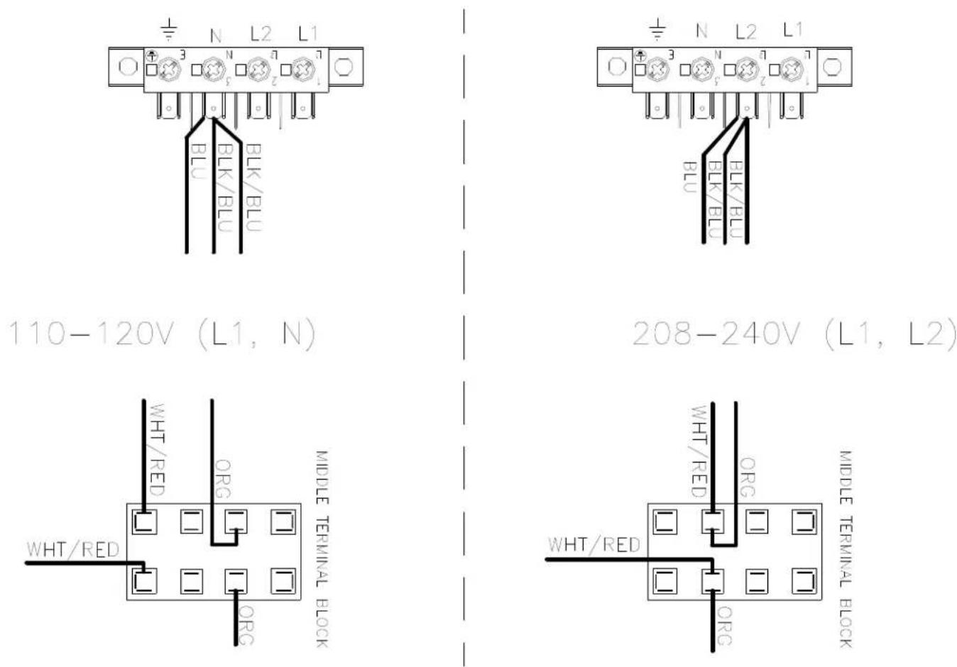
- Move the red wire from the 120V tap on the transformer found in the bottom of control box to the required voltage tap based on actual supply voltage measurement. See figure below.
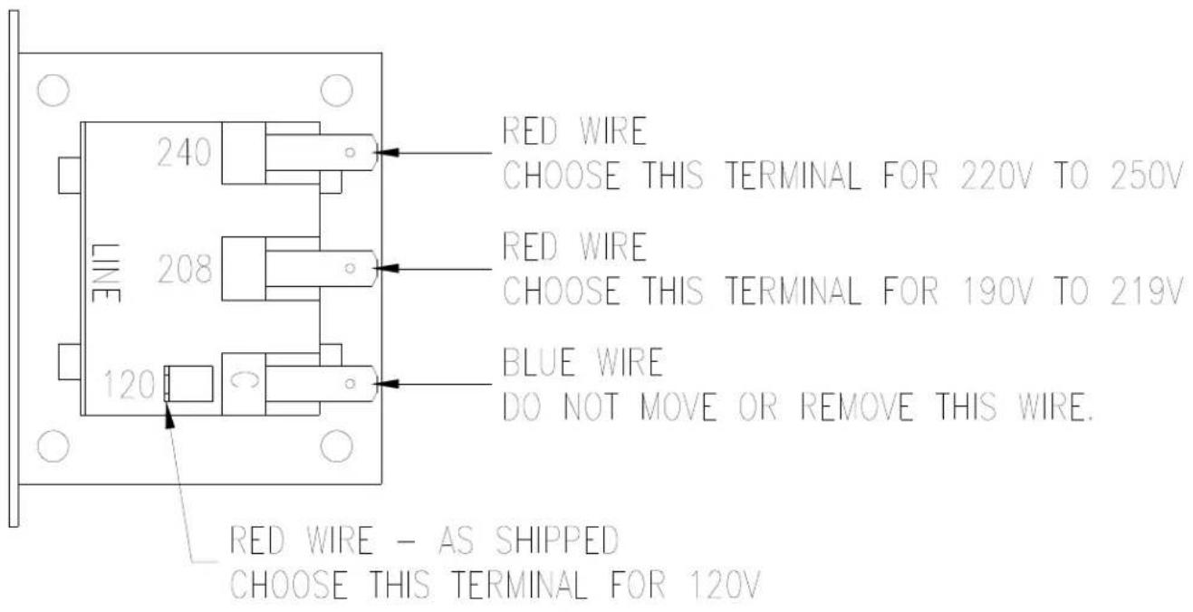
CONTROL TRANSFORMER CONNECTIONS AS VIEWED FROM SIDE OF TRANSFORMER
- Reconnect power to the dryer and test to ensure proper operation; one line voltage to L1, one line voltage to L2 and the earth ground to E.
- Reinstall the cover of the control box assembly on the dryer using a 5 / 16'' wrench.
Failure to follow safety warnings exactly could result in serious injury, death or property damage.
-
Do not store or use gasoline or other flammable vapors and liquids in the vicinity of this or any other appliance.
WHAT TO DO IF YOU SMELL GAS -
Do not try to light any appliance.
- Do not touch any electrical switch; do not use any phone in your building.
- Clear the room, building or area of all occupants.
- Immediately call your gas supplier from a neighbor's phone. Follow the gas supplier's instructions.
-
If you cannot reach your gas supplier, call the fire department.
-
Installation and service must be performed by a qualified installer, service agency or the gas supplier.
Do not store or use gasoline or other flammable vapors or liquids in the vicinity of this or any other appliance.
Tension/Hz/Phase 120 V/60 Hz/Monophasé
Tension/Hz/Phase 208-240 V/60 Hz/Monophasé
Tension/Hz/Phase 230V/50Hz/Monophasé
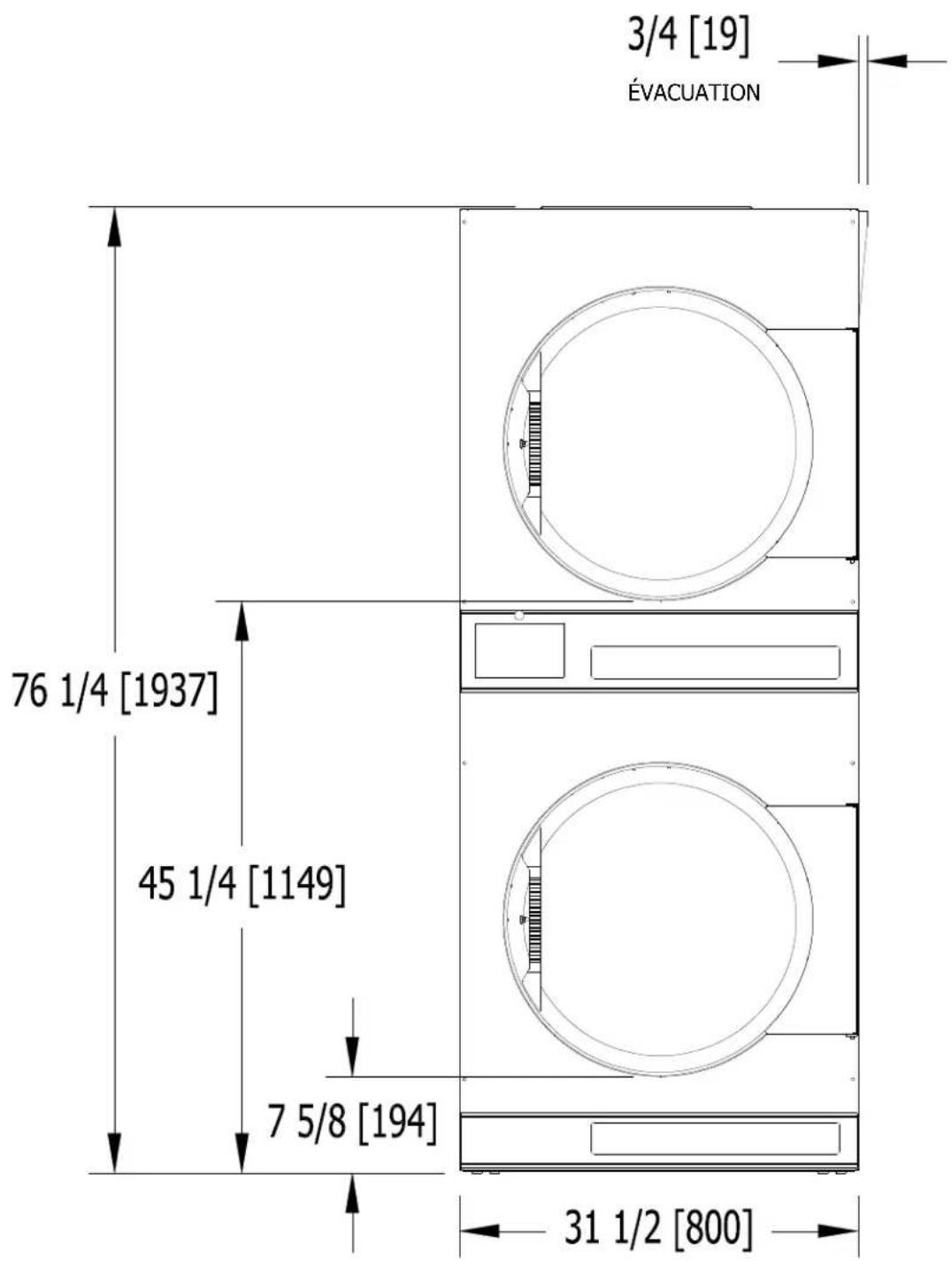
DIMENSIONS ARE IN INCHES [MILLIMETERS]
DIMENSIONS DE LA SÉCHEUSE T-30X2 - VUE DE CÔTE
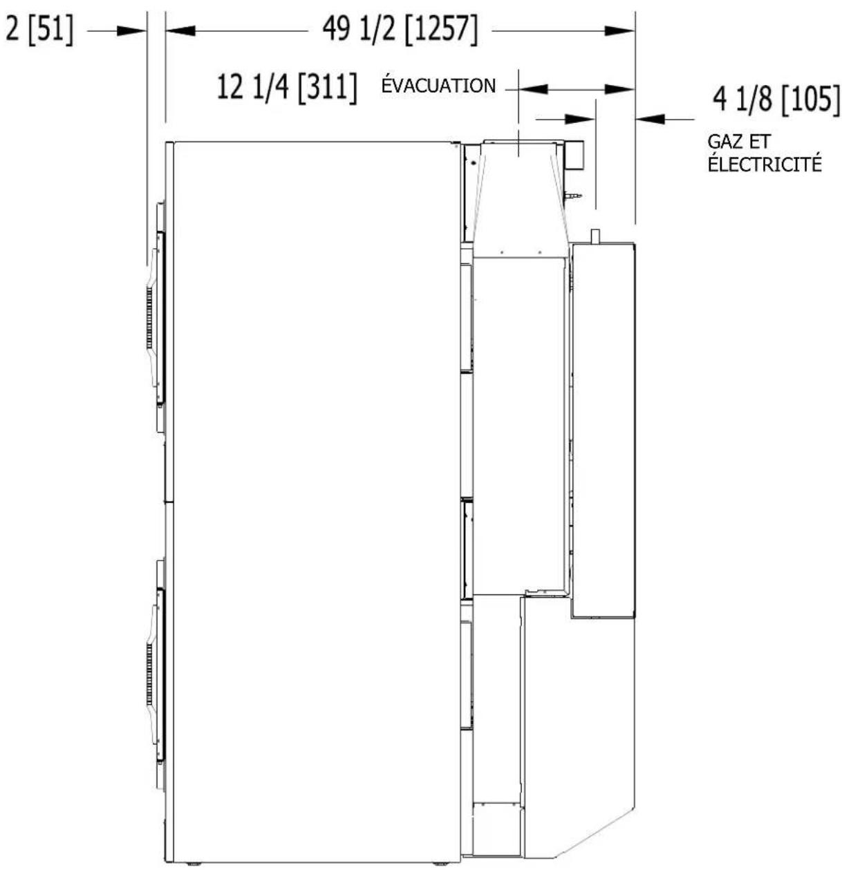
LES DIMENSIONS SONT EN POUCES (MILLIMÉTRES)
DIMENSIONS DE LA SÉCHEUSE T-30X2 - VUE DE DERRIÈRE
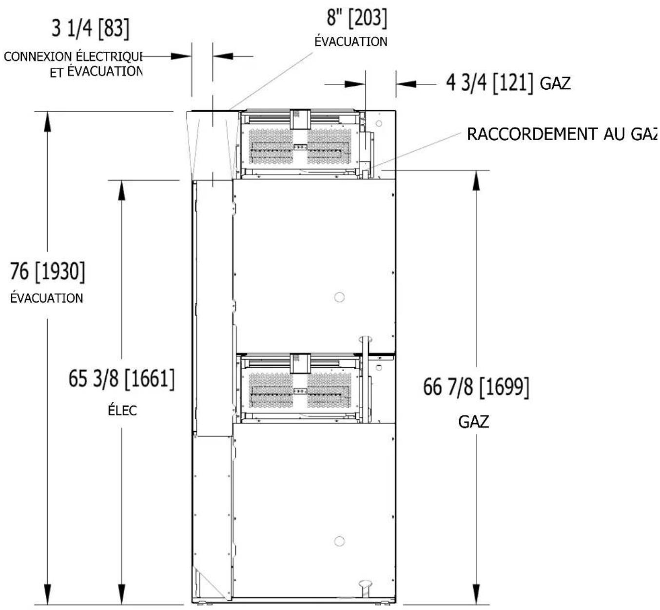
LES DIMENSIONS SONT EN POUCES (MILLIMÉTRES)
DIMENSIONS DE LA SÉCHEUSE T-50X2 - VUE DE FACE
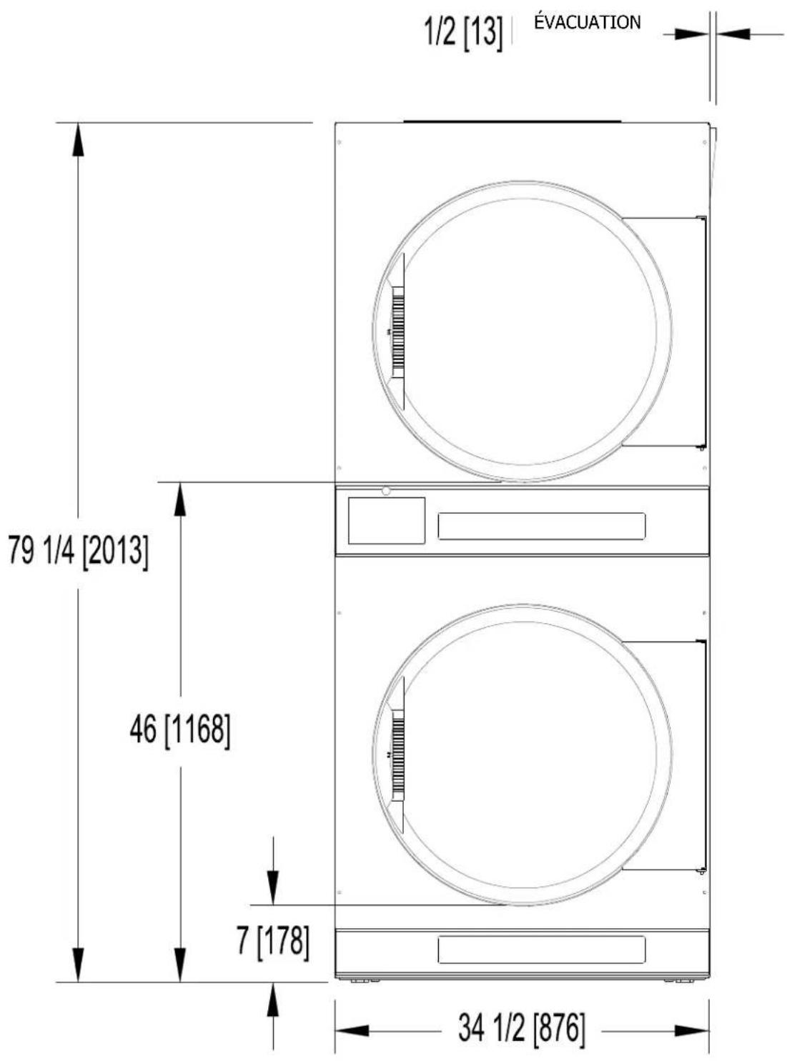
DIMENSIONS ARE IN INCHES [MILLIMETERS]
DIMENSIONS DE LA SÉCHEUSE T-50X2 - VUE DE CÔTE
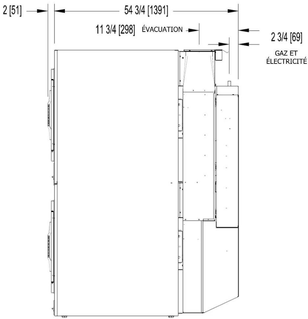
LES DIMENSIONS SONT EN POUCES (MILLIMÉTRES)
DIMENSIONS DE LA SÉCHEUSE T-50X2 - VUE DE DERRIÈRE
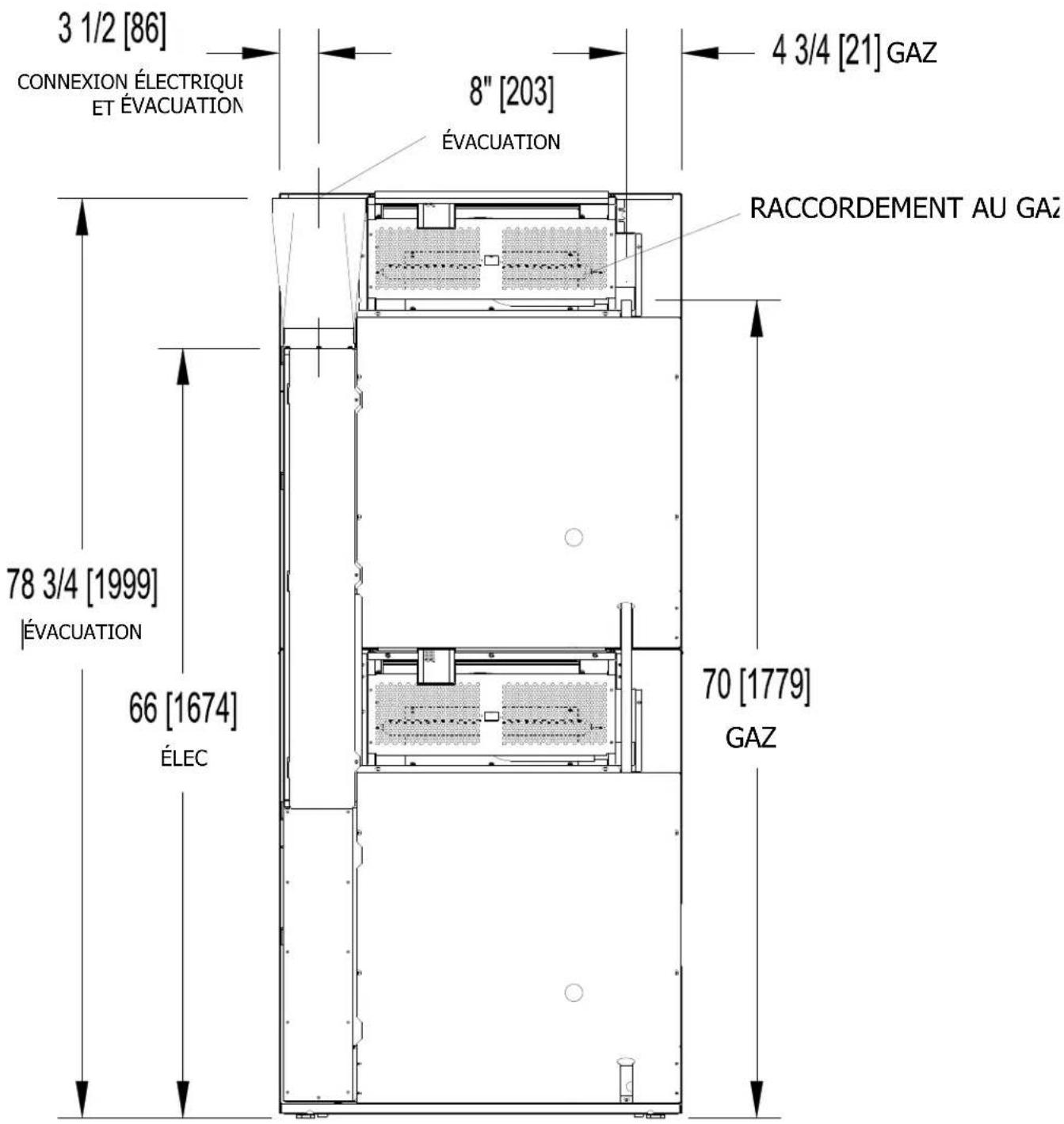
LES DIMENSIONS SONT EN POUCES (MILLIMÉTRES)
INSTRUCTIONS D'INSTALLATION
Site Web: www.dexter.com