
PLS120 - Heating DELONGHI - Free user manual and instructions
Find the device manual for free PLS120 DELONGHI in PDF.
| Product type | Reversible air conditioner (heating and cooling) |
| Brand | DeLonghi |
| Model | PLS120 |
| Indoor unit dimensions (W×H×D) | 1000 × 290 × 155 mm |
| Outdoor unit dimensions (W×H×D) | 763 × 515 × 258 mm |
| Power supply | Single phase, 230 V / 50 Hz |
| Heating power | Not specified in the manual (HEAT function up to 30°C setpoint) |
| Refrigerant | R410A (GWP=1975) |
| Main functions | Heating, cooling, dehumidification, ventilation, Smart mode (auto), Turbo Power, I Comfort, Sleep, Timer |
| Heating temperature range | 16°C – 30°C |
| Remote control | Yes, with AAA batteries (2×1.5V) |
| Display | LED display with Light function (night dimming) |
| Filters | Washable air filter, antibacterial silver ion filter, biological electrostatic deodorizing filter (depending on version) |
| Maintenance and cleaning | Clean the air filter with water (max 45°C); replace special filters every 6 months; unplug before any operation |
| Safety | High and low pressure protection, cold air prevention, overload protection, automatic shutdown in case of anomaly |
| Spare parts and repairability | Contact an authorized DeLonghi technical service; repairs reserved for qualified personnel |
| General information | Compliant with European directives (Low Voltage, EMC); fluorinated greenhouse gas; disposal at specialized center |
| Flexible hose length | 4 m (3 m usable) |
| Remote control distance | Up to 8 m |
| Weight (approximate) | Not specified, approximately 30-40 kg (indoor + outdoor unit) |
Frequently Asked Questions - PLS120 DELONGHI
User questions about PLS120 DELONGHI
0 question about this device. Answer the ones you know or ask your own.
Ask a new question about this device
Download the instructions for your Heating in PDF format for free! Find your manual PLS120 - DELONGHI and take your electronic device back in hand. On this page are published all the documents necessary for the use of your device. PLS120 by DELONGHI.
USER MANUAL PLS120 DELONGHI
Cod. 5717310011, Rev. 00 (07/2007), Page: 19

Thank you for having chosen a
DeLonghi PRC705, air conditioner, which is an innovative,
high quality product designed to ensure your wellbeing.
This instruction booklet contains important information and recommendations that we would ask you to comply with to obtain best results from your air conditioner.
We thank you once again.
De'Longhi Group
In line with the company's policy of continual product improvement, the aesthetic and dimensional characteristics, technical data and accessories of this appliance may be changed without notice.
CONTENTS
GENERAL INFORMATION
GENERAL INFORMATION Page.
Conformity and range.
Safety rules and recommendations. 2
Safety rules and prohibitions 3
Names of the parts. 3
Technical data. 4
USER
Operation and EEC
(Electronic Climate Control) display. 5
Remote control. 5
Modes of operation. 7
COOLING mode. 8
HEATING mode. 8
SMART mode. 8
TIMER mode 9
DRY mode 9
FAN mode 9
SLEEP mode 10
TURBO POWER function. 10
I COMFORT function 10
LIGHT function 10
INSTALLATION
Handling 11
Installing the indoor unit.
Installing the outdoor unit. 13
Maintenance 16
Possible errors. 17
Troubleshooting 17
Disposal. 18
Environmental information 18
Useful information. 18
CONFORMITY AND RANGE
GENERAL INFORMATION
The air conditioner you have purchased is in conformity with the following European Directives:
Low Voltage 73/23/EEC
- Electromagnetic compatibility 89/336/EEC
CE
Read this guide before installing and using the appliance.
! Check that air cannot enter the refrigerant system and check for refrigerant leaks when moving the air conditioner.
! Carry out a test cycle after installing the air conditioner and record the operating data.
The ratings of the fuse installed in the built-in control unit are 2.5 A, E, 250V.
The user is responsible for having the appliance installed by a qualified technician, who must check that the system is earthed in accordance with current legislation and regulations and install a double-pole thermomagnetic circuit breaker having a contact separation of at least 3.5mm in both poles.
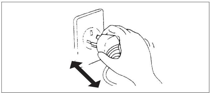
! Ensure that the mains voltage corresponds to that stamped on the rating plate. Keep the switch or power plug clean. Insert the power plug correctly and firmly into the socket, thereby avoiding the risk of electric shock or fire due to insufficient contact.
Check that the socket is suitable for the plug, otherwise have the socket changed.
Make sure that the base of the outdoor unit is firmly fixed.
! Do not install the appliance at a distance of less than 50 cm from inflammable substances (alcohol, etc.) or from pressurised containers (e.g. spray cans).
If the appliance is used in areas without the possibility of ventilation, precautions must be taken to prevent any leaks of refrigerant gas from remaining in the environment and creating a danger of fire
The packaging materials are recyclable and should therefore be disposed of in the relative separate waste bins. Take the air conditioner at the end of its useful life to a special waste collection centre for disposal.
Only use the air conditioner as instructed in this booklet. These instructions are not intended to cover every possible condition and situation. As with any electrical household appliance, common sense and caution are therefore always recommended for installation, operation and maintenance.
The appliance must be installed in accordance with applicable national regulations.
! Before accessing the terminals, all the power circuits must be disconnected from the power supply.
Do not pull out the plug to switch off the appliance when it is in operation, since this could create a spark and cause a fire, etc.
Prolonged exposure to cold air is harmful to health.
If the appliance gives off smoke or there is a smell of burning, immediately cut off the power supply and contact the Service Centre.
Have repairs carried out only by an authorised Service Centre of the manufacturer. Incorrect repair could expose the user to the risk of electric shock, etc.
Ensure that the appliance is disconnected from the power supply when it will remain inoperative for a long period and before carrying out any cleaning or maintenance.
This appliance must only be used by adults; do not allow children or persons with reduced psycho-physical-sensorial abilities to use it.
! Selecting the most suitable temperature can prevent damage to the appliance.
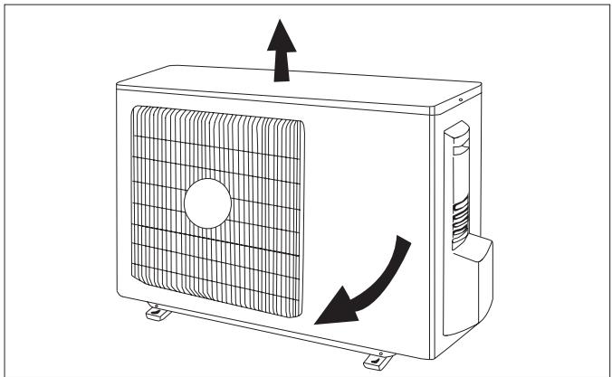
The airflow direction must be properly adjusted. The flaps must be directed downwards in the heating mode and upwards in the cooling mode.
This appliance has been made for air-conditioning domestic environments and must not be used for any other purpose, such as for drying clothes, cooling food, etc.
Cleaning and maintenance must be carried out by specialised technical personnel. In any case disconnect the appliance from the mains electricity supply before carrying out any cleaning or maintenance.

Do not bend, tug or compress the power cord since this could damage it. Electrical shocks or fire are probably due to a damaged power cord.
Specialised technical personnel only must replace a damaged power cord.

Do not use extensions or gang modules.
Do not touch the appliance when barefoot or parts of the body are wet or damp.

Do not obstruct the air inlet or outlet of the indoor or the outdoor unit.

In no way alter the characteristics of the appliance.
Do not install the appliance in environments where the air could contain gas, oil or sulphur or near sources of heat.

Do not climb onto or place any heavy or hot objects on top of the appliance.

Do not leave windows or doors open for long when the air conditioner is operating.

Do not direct the airflow onto plants or animals.

Do not spray water onto the air conditioner.

Do not climb onto or place any objects on the outdoor unit

Never insert a stick or similar object into the appliance. It could cause injury.

Children and unassisted disabled persons must not use the appliance.
NAMES OF THE PARTS
GENERAL INFORMATION
| INDOOR UNIT | |
| No. | Description |
| 1 | Front panel |
| 2 | Air filter |
| 3 | Antibacterial silver ion filter (if installed) |
| 4 | Deodoriser biologic electrostatic filter (if installed) |
| 5 | Terminal block cover |
| 6 | Reset button |
| 7 | ECC LED display |
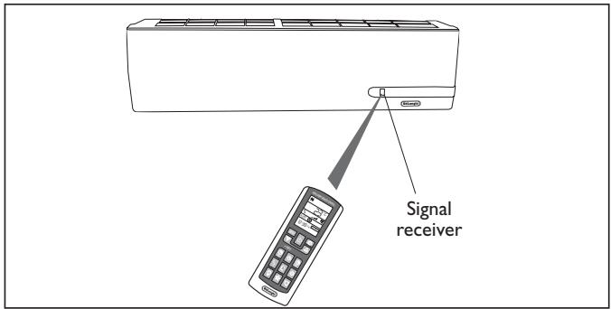
| 8 | Signal receiver |
| 9 | Airflow direction flaps |
| 10 | Push-pull connector |
| 11 | Preloaded flexible sheath length 4 m (3 m are useable) |
| 12 | Push-fit connector for refrigerant fittings |
| 13 | Intelligent remote control |
| 14 | Spirit level (provided in the kit) |
| UNITA' ESTERNA | |
| N. | Descrizione |
| 15 | Air outlet grille |
| 16 | Handle |
| 17 | Push-fit male connector for refrigerant connections |
| 18 | Fittings cover |
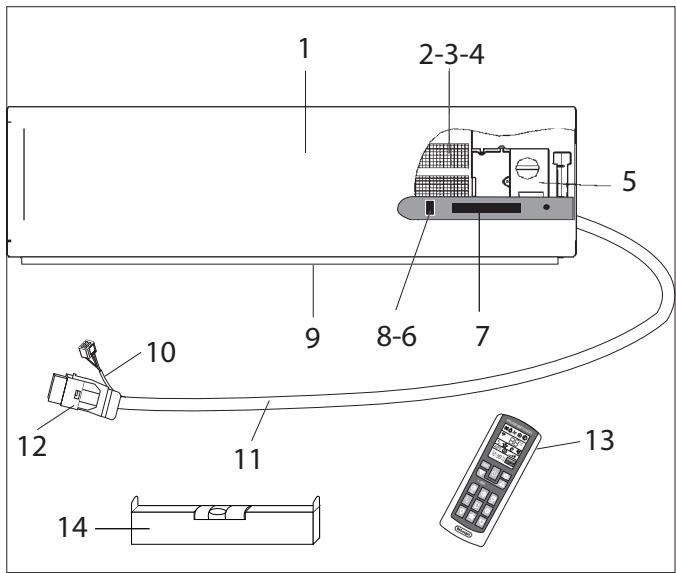
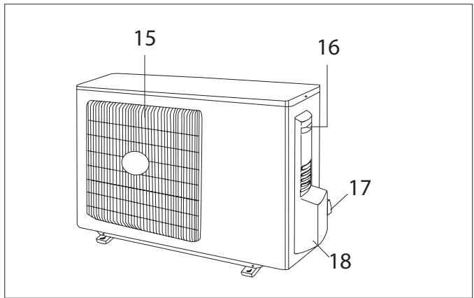
Note: the above figures are only intended to be a simple diagram of the appliance and may not correspond to the appearance of the units that have been purchased.
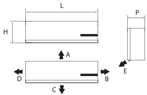
Size and clearance
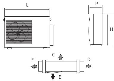
| L | 1000 | mm |
| H | 290 | mm |
| P | 155 | mm |
| A | 150 | mm |
| B | 150 | mm |
| C | 2500 | mm |
| D | 150 | mm |
| E | 300 | mm |
| L | 763 | mm |
| P | 258 | mm |
| H | 515 | mm |
| C | 500 | mm |
| D | 300 | mm |
| F | 300 | mm |
| E | 2000 | mm |
Operating limits (7K - 9K e 12K ON-OFF models)
| Internal part bulb °C | External part bulb °C | |
| Cooling (Max ; Min) | 36 ; 16 | 45 ; +18 |
| Heating (Max ; Min) | 30 ; 27 | 16 ; -10 |
| Operating limits (9K e I2K DC-INVERTER models) | ||
| Internal part bulb °C | External part bulb °C | |
| Cooling (Max ; Min) | 36 ; 16 | 45 ; -10 |
| Heating (Max ; Min) | 30 ; 16 | 27 ; -15 |
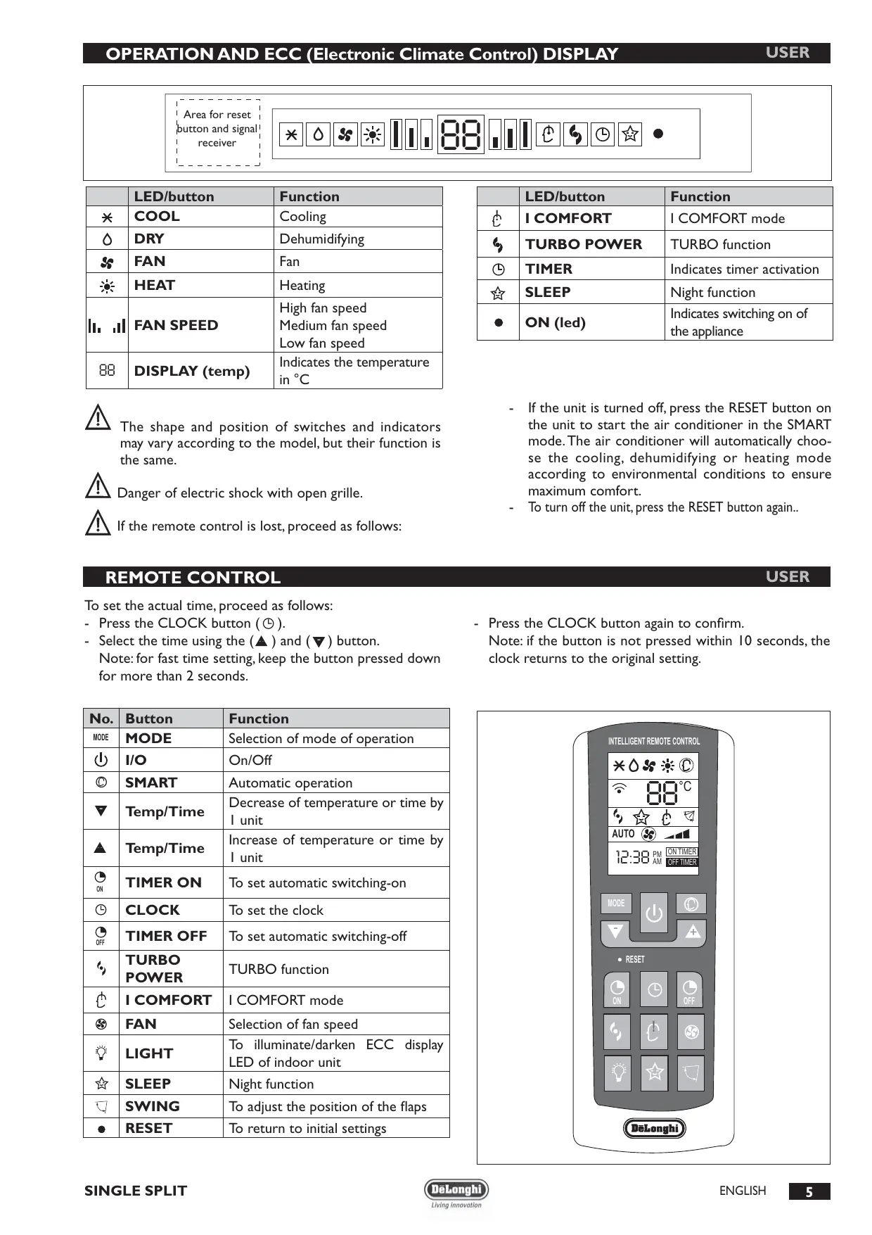
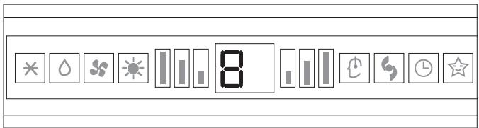
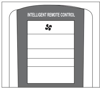
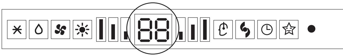
Area for reset button and signal receiver

| LED/button | Function | |
| * | COOL | Cooling |
| △ | DRY | Dehumidifying |
| SS | FAN | Fan |
| HEAT | HEATING | |
| II, III | FAN SPEED | High fan speed Medium fan speed Low fan speed |
| 88 | DISPLAY (temp) | Indicates the temperature in °C |

The shape and position of switches and indicators may vary according to the model, but their function is the same.

Danger of electric shock with open grille.

If the remote control is lost, proceed as follows:
| LED/button | Function | |
| I | I COMFORT | I COMFORT mode |
| S | TURBO POWER | TURBO function |
| O | TIMER | Indicates timer activation |
| ☆ | SLEEP | Night function |
| ● | ON (led) | Indicates switching on of the appliance |
- If the unit is turned off, press the RESET button on the unit to start the air conditioner in the SMART mode. The air conditioner will automatically choose the cooling, dehumidifying or heating mode according to environmental conditions to ensure maximum comfort.
- To turn off the unit, press the RESET button again...
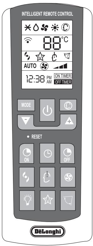
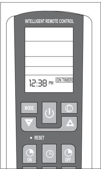
REMOTE CONTROL
USER
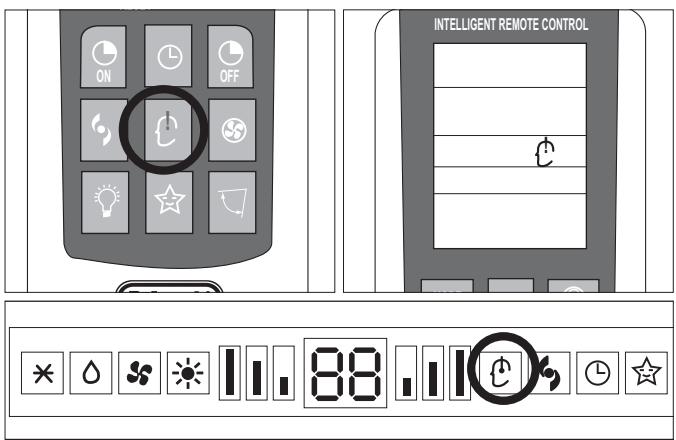
To set the actual time, proceed as follows:
- Press the CLOCK button (①).
- Select the time using the () and () button.
Note: for fast time setting, keep the button pressed down for more than 2 seconds.
- Press the CLOCK button again to confirm.
Note: if the button is not pressed within 10 seconds, the clock returns to the original setting.
| No. | Button | Function |
| MODE | MODE | Selection of mode of operation |
| I | I/O | On/Off |
| SMART | Automatic operation | |
| Temp/Time | Decrease of temperature or time by 1 unit | |
| Temp/Time | Increase of temperature or time by 1 unit | |
| TIMER ON | To set automatic switching-on | |
| CLOCK | To set the clock | |
| TIMER OFF | To set automatic switching-off | |
| TURBO POWER | TURBO function | |
| I COMFORT | I COMFORT mode | |
| FAN | Selection of fan speed | |
| LIGHT | To illuminate/darken ECC display LED of indoor unit | |
| SLEEP | Night function | |
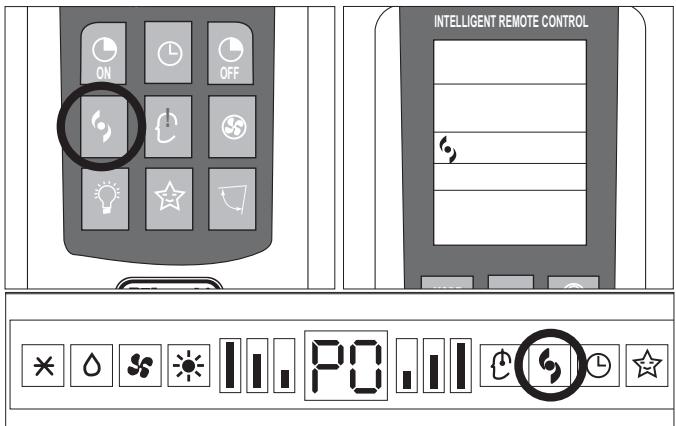
| SWING | To adjust the position of the flaps | |
| RESET | To return to initial settings | |
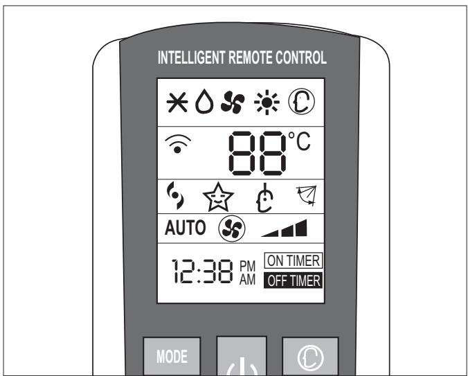
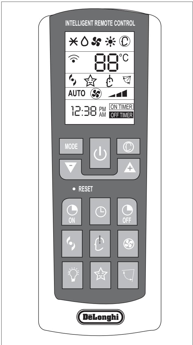
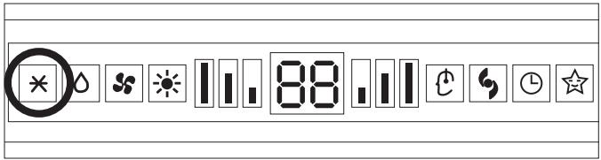
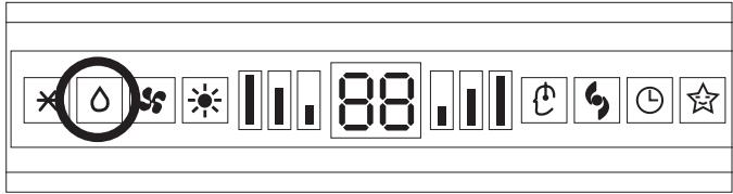
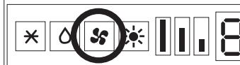
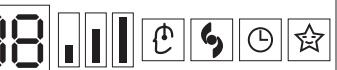
Meaning of symbols on the liquid crystal display
| AUTO | Operation in automatic mode indicator |
| - | Low fan speed |
| - | Medium fan speed |
| - | High fan speed |
| * | Cooling indicator |
| △ | Dehumidifying indicator |
| # | Fan only operation indicator |
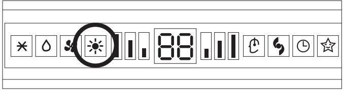
| ※ | Heating indicator |
| ☆ | SLEEP indicator |
| # | Flap swing indicator |
| # | TURBO indicator |
| # | I COMFORT indicator |

The remote control display remains active even when the unit is not in operation.
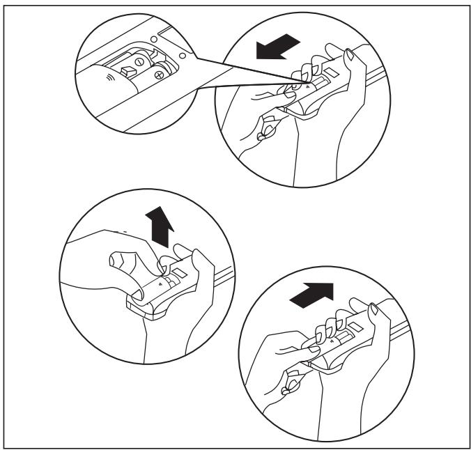
How to insert the batteries
- Remove the cover from the battery compartment, by sliding it in the direction of the arrow.
- Insert the new batteries, ensuring that the (+) and (-) directions are correct.
- Refit the cover by sliding it into place.

Use 2 RO3 AAA (1.5V) batteries. Do not use rechargeable batteries.
Replace the old batteries with new ones of the same type when the display is no longer legible.
The remote control batteries must be disposed of in accordance with the applicable laws in force in the country of use.
How to use the remote control
To start the air conditioner, point the remote control at the signal receiver. The remote control works up to a maximum distance of 8 metres from the indoor unit.

Keep the remote control at a distance of at least I m from the television or other electrical appliances.
| Mode of operation | ||
| I | I/O | On/Off/Stand-by |
| FAN (Fan mode) | Every time the FAN button is pressed the speed changes in the following sequence: AUTO - LOW - MEDIUM - HIGH. The remote control also stores the speed that was set in the previous mode of operation. | |
| SWING | Adjustment of airflow. Press the “SWING” button to start the automatic swing of the airflow direction flaps; press the “SWING” button again to stop the movement. If the appliance is operating in the HEAT mode when the “SWING” button is pressed, the start of this function will be deliberately delayed for a few seconds to ensure the immediate outflow of warm air for user comfort (Hot-Start function). | |
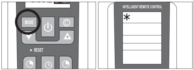
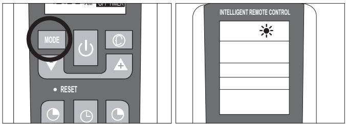
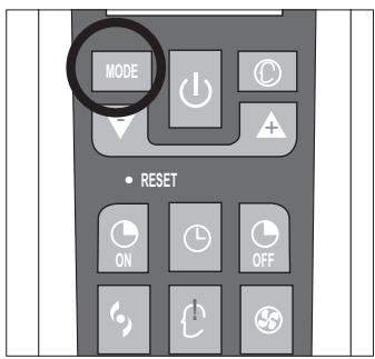
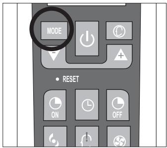
| MODE | MODE | Selection of mode of operation. Every time the MODE button is pressed the mode of operation changes in the following sequence: COOLING - DRY - FAN - HEATING. |
| Buttons (+) and (-) | Setting of temperature. Press once to raise (+C°) or lower (-C°) the set temperature by 1°C. Available range of temperature settings: HEATING 16°C ~ 30°C COOLING 16°C ~ 30°C DEHUMIDIFYNG 16°C ~ 30°C FAN 16°C ~ 30°C | |
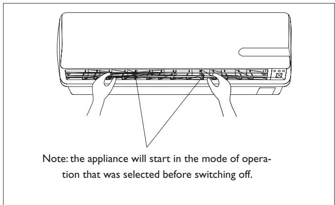
Note: the appliance will start in the mode of operation that was selected before switching off.
Do not turn the vertical airflow direction flaps by hand, since this could cause malfunctioning. In the case of flap malfunction, first of all switch off the appliance, disconnect it from the power supply and then reconnect it.
Adjustment of horizontal airflow (manual)
To change the angle of the airflow, turn the adjusting cursors of the horizontal airflow direction flaps as shown. Note: the unit shown here may be different from the air conditioner you have purchased.

This adjustment must be done with the appliance switched off.
The cooling function allows the air conditioner to be started and used as a producer of cool air.
To activate the cooling function (COOL), press the MODE button until the symbol (×) appears on the display.
To change the temperature value, use the (▼ and ▲). buttons. Each time the buttons are pressed the set temperature value increases or decreases by 1^ .
HEATING MODE
USER
The heating function allows the air conditioner to be started and used as a producer of hot air.
To activate the heating function (HEAT), press the MODE button until the symbol (水) appears on the display.
To change the temperature value, use the ( and ). buttons. Each time the buttons are pressed the set temperature value increases or decreases by 1^ .
The appliance is fitted with a Hot Start function, which delays appliance start-up for a few seconds to ensure an immediate output of hot air.
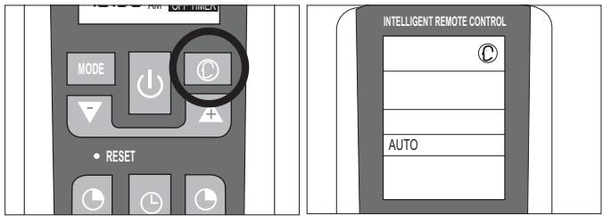
SMART MODE
USER
Automatic mode
To activate the SMART function, press the (C) button on the remote control. The writing AU (AUTO) will appear on the display.
In the SMART mode the fan speed and the temperature are set automatically according to the room temperature to ensure user comfort.
| Room temperature | Mode |
| 23°C ~ 26°C | FAN ONLY |
| Above 26°C | COOLING |
| Below 23°C | HEATING |
Note: after having stopped the SMART function, the air conditioner will start up with the settings of the previously selected modes.

Before setting the timer, ensure that the time on the remote control is set correctly. If it is not, consult the instructions given on page 5.
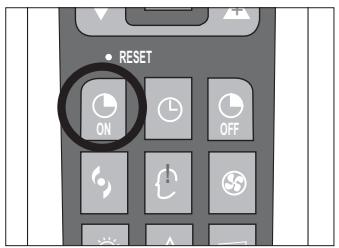
Automatic switching-on
To set the automatic switching-on of the air conditioner, proceed as follows:
- With the appliance switched off, press the button TIMER ON (ON).
- Set the automatic switching-on time using the (+) and (-) buttons.
- Press the TIMER ON button within 10 seconds to confirm otherwise the function will exit from time setting.
Note: to cancel the function setting, press the TIMER ON button again.
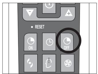
Automatic switching-off
To set the automatic switching-off time, proceed as follows:
- Press the TIMER OFF (按钮).
- Set the automatic switching-off time using the (+) and (-) buttons.
- Press the TIMER OFF button within 10 seconds to confirm, otherwise the function will exit from time setting.
Note: to cancel the function setting, press the TIMER OFF button again.
Note: it is also possible to set the appliance switching-on and switching-off time so as to define a specific duration of operation.
Note: the appliance will start in the mode of operation that was selected before switching off.
DRY MODE
USER
Dehumidifying mode
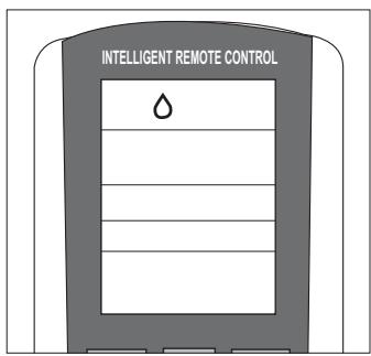
Press the MODE button until the DRY symbol () appears.
The appliance activates according to the room and the set temperature:
- If the room temperature is 2^ C lower than the set temperature, the compressor and the outdoor unit stop while the indoor unit fan operates at low speed.
- If the room temperature is 2^ C higher than the set temperature, the appliance automatically passes to the dehumidifying function, activating the fan at low speed.
FAN MODE
USER
Fan mode
Press the MODE button until the FAN ( ) symbol appears. Every time the FAN button is pressed the speed changes in the following sequence: AUTO - LOW - MEDIUM - HIGH. The remote control also stores the speed that was set in the previous mode of operation.
In the AUTO mode, the air conditioner automatically chooses the fan speed and the mode of operation (COOLING or HEATING).
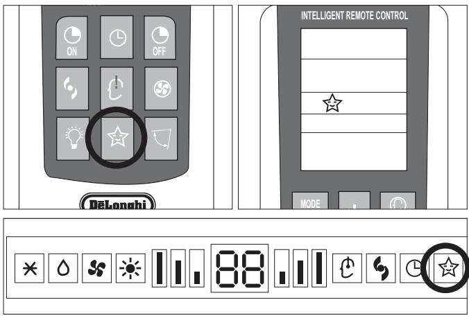
Night mode
To activate the night function in the COOL, DRY and HEAT modes, press the SLEEP (☆) button. The symbol ☆ appears on the display. To deactivate the night function, press the SLEEP (☆) button again.
During operation in the night mode, the set temperature increases by 1^ in the first hour of operation and by another 1^ in the following hour, maintaining this increase of 2^ in the subsequent hours.
Selecting the night function in the heating mode, the set temperature decreases by 1^ in the first hour of operation and by another 1^ in the following hour, maintaining this decrease of 2^ in the subsequent hours with the fan operating at minimum speed.
TURBO POWER FUNCTION
USER
To activate the TURBO POWER function, press the 心 button. The symbol 心 appears on the display..
In the COOL or HEAT mode, the air conditioner will automatically operate at maximum power. To deactivate this function just change the fan speed or press the button again.
I COMFORT FUNCTION
USER
Press the I COMFORT (b) button and the symbol appears on the display.
This function is used to obtain the required climate in the exact point where the remote control is located. The temperature of reference is that measured by the sensor in the remote control, bypassing the temperature sensor inside the air conditioner.

The remote control must always by pointed at the unit.

If no signal is received from the remote control for 11 minutes, the unit will once again refer to its own internal sensor.
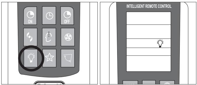
LIGHT FUNCTION
USER
Press the LIGHT ( ), button and the symbol appears on the display. Upon activating this function the LEDs on the indoor unit display go out while air conditioner operation remains unchanged. This function is useful at night when the display lights could be bothersome.
Note: not all the above functions are present on all models of air conditioner.
Carefully remove the adhesive strips from the appliance.
After having removed the packaging, check that the contents are intact and complete.

The outdoor unit must always be kept upright.

Handling must be done by suitably equipped qualified technical personnel using equipment that is suitable for the weight of the appliance.
INSTALLING THE INDOOR UNIT
USER
Before starting installation, decide on the position of the indoor and outdoor units, taking into account the minimum clearance required around the units (see technical data table).

Install the indoor unit in the room to be air conditioned, avoiding installations in corridors or communal areas.

Ensure that there is a mains socket very close to the indoor unit where it can be plugged in.

Install the indoor unit at a height of at least 2.5m from the ground.
LOCATING THE INDOOR UNIT

The indoor unit must be wall mounted.

It must be located so that the treated air can circulate throughout the room.
To install the indoor unit proceed as follows:
Installing the mounting plate
- Remove the screws from the plate, which is attached to the rear of the unit.
- Remove the plate;
- Place it against the wall at the point where it is to be installed, using a spirit level (provided in the kit) to ensure that it is horizontal and complying with the minimum clearance indicated in the figure.
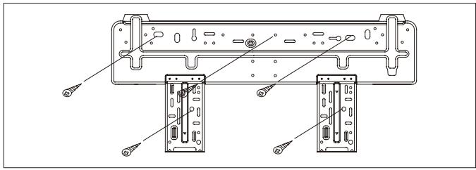
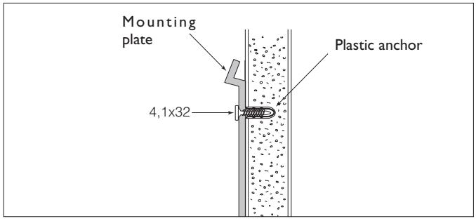
Using a pencil, mark the position of the holes for the screw anchors on the wall. - Drill 32mm deep holes in the wall for fixing the plate.
- Insert the plastic anchors into the hole.
Fix the mounting plate to the wall using the anchors and the self-tapping screws provided in the kit. - Check that the mounting plate is correctly fixed.
- Check again that the plate is level.
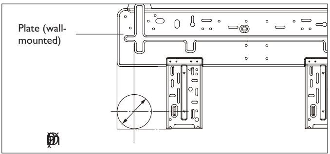
Drilling a hole in the wall for the piping
- Decide where to drill the hole in the wall for the piping according to the position of the mounting plate (see figure)
Using compasses, mark the circumference ( 90mm) of the hole for the connections to pass through.

The hole must be drilled in the left side of the unit in line with the refrigerant outlet connections.
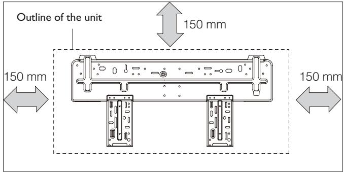
Recommended minimum clearance
Note: when the product is delivered the mounting plate is attached to the rear of the indoor unit. It may be a different shape to the one shown above, but the method of installation is the same.
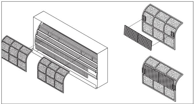
Before installing the indoor unit, mount the silver ion and biological electrostatic filters (if ordered).
To install the filters:
- Take out the mesh filter.
- Attach the silver ion and the biological electrostatic (if ordered) filters.
- Refit the filters inside the indoor unit, proceeding in the reverse order to above.
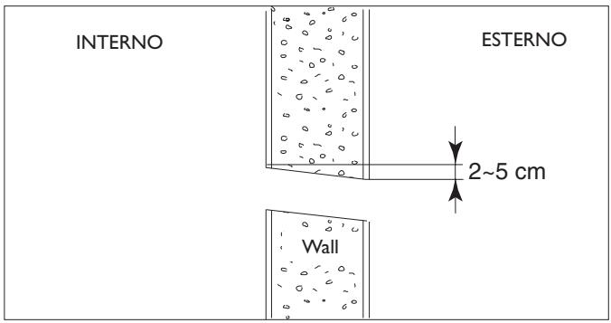
Using a wall borer-cutter (not provided), make a hole for the refrigerant connections to pass through. NB: if you do not have a borer-cutter available, the hole can be made using a drill and drilling lots of holes close to each other around the marked circumference.

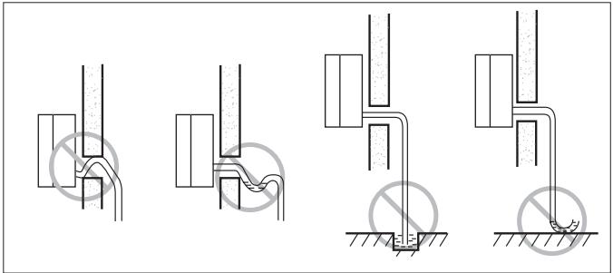
The hole must slope gently downwards towards the exterior.
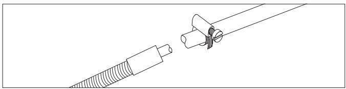
Connecting the condensate outlet pipe
The indoor unit is fitted with a condensate outlet pipe to which a drain pipe must be connected that leads to a suitable place for drainage.
- Connect an insulated drain pipe ( i 16 mm) to the outlet pipe connection using a hose clamp or adhesive tape.
- Check that the condensate flows out regularly.

The drain pipe must have a minimum slope of 3% towards the drain.

Check all the joints for leaks.

Lag the joints.

Avoid upturned sections.
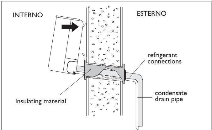
Passing through the connections
- Pass the condensate drain pipe and the flexible sheath containing the refrigerant connections through the previously made hole.
- Fit the indoor unit onto the mounting plate, passing the pipes through the previously made hole.

To avoid damaging the fittings, before passing the sheath through the hole in the wall, it is advisable to protect the ends of the push-fit connections with the plugs provided in the kit or with adhesive paper tape.
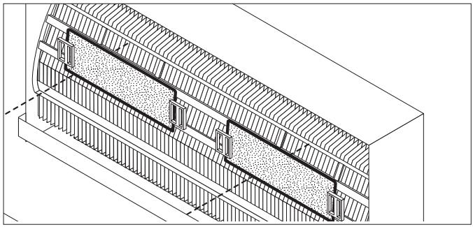
LOCATING THE OUTDOOR UNIT

The outdoor unit may stand on the floor or be wall mounted, provided it is well supported and vibrations are not transmitted to adjacent rooms.
It is advisable to avoid installation:

In pits or air vents;

Where obstacles or barriers could cause the expelled air to recirculate;

In places with an aggressive atmosphere;

In restricted places where the noise level of the appliance could be increased by reverberation or resonance;

in corners where dust, leaves or such usually accumulate and could reduce appliance efficiency by obstructing the passage of air.
Floor standing
When installing on the floor or a flat deck, the feet need not be fixed to the ground. Supports are instead placed underneath ( 90÷ 100mm) to allow application of the condensate drain pipe.
Place vibration-isolation mountings (not provided in the kit) between the feet and the supporting base.
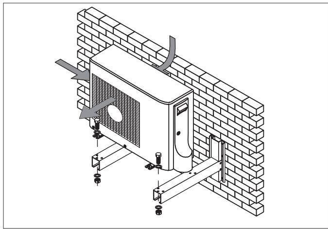
Wall mounted
When wall mounting, the recommended minimum clearance must be observed and a supporting kit is used that must be ordered separately.
Carefully check that the structure and the load-bearing capacity of the supporting wall are suitable.

Ensure that the recommended clearance given in the "Technical Data" table is left around the appliance.

The manufacturer cannot be held liable for any damage or injury caused by failure to earth the appliance or to comply with the instructions given in this booklet.

Where air expelled from the appliance could enter inhabited rooms through doors or windows, since this would cause discomfort to the persons indoors;

Where air expelled from the appliance is opposed by wind in the opposite direction;

Where sunlight falls directly on the appliance.

Before starting installation, decide on the position of the indoor and outdoor units, taking into account the minimum clearance required, the max. length of the refrigerant lines and the difference in level between the units.
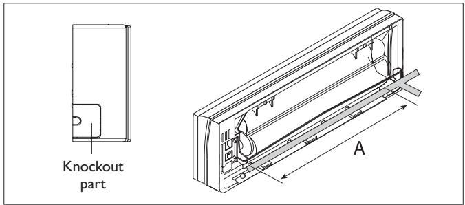
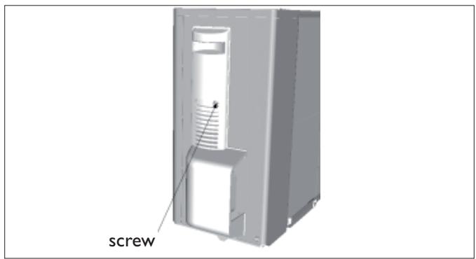
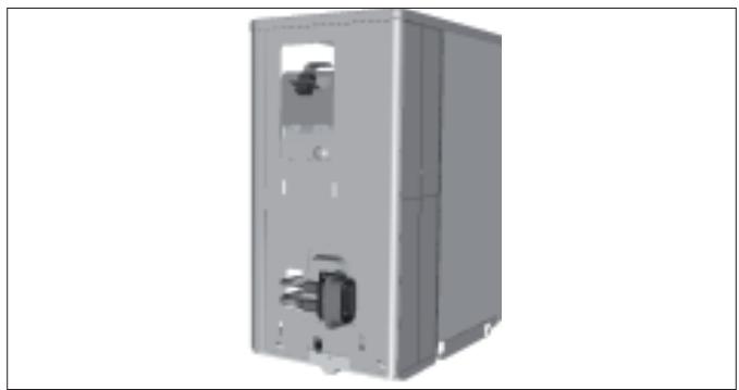
- Loosen the fixing screw indicated by the arrow.
- Press the handle downwards and remove the panel protecting the terminals in order to carry out the electrical connection.
- The user must remove the tamperproof closures indicated in the figure before installation.
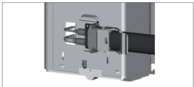
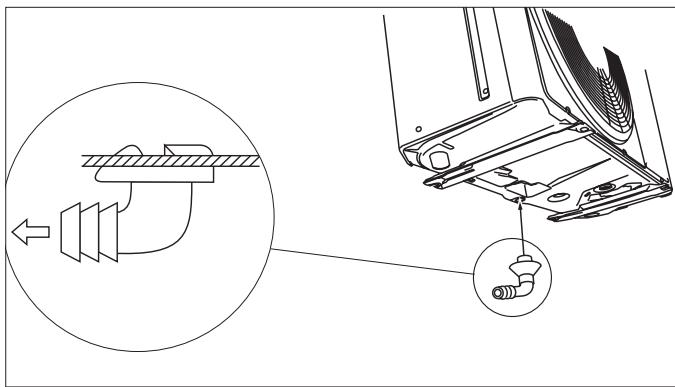
- Take off the clip from the push-pull connector (male plug).
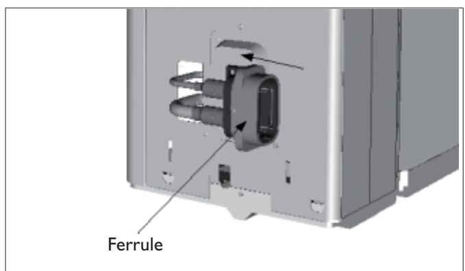
Pull the ferrule inwards as indicated by the arrow.

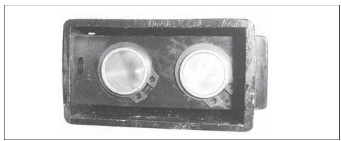
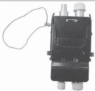
Before carrying out the connection remove the cover protecting the connections by sliding back the lockout.
- Insert the push-pull connector (male plug) into the female socket and re-position the fixing cable at the same time.

The locating pin must be facing downwards.
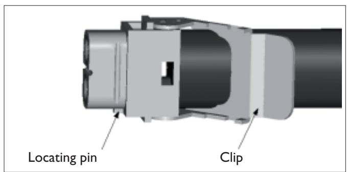
- Rotate the clip and press it down as far as it will go.
It is difficult to press the clip down fully if the fixing cable has not been properly re-positioned.
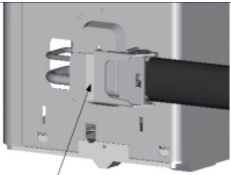
After fully closing the push-pull connection, insert the shear pin into the relative hole shown in the figure. - Connect the cable terminal
- Secure the cable to the appliance using the clamping device provided.
- Mount the large handle.
Connecting the condensate drain hose
- Connect an insulated drain pipe ( i 16 mm) to the outlet pipe connection and take to a suitable place for drainage.
- Check that the condensate flows out regularly.

Check all the joints for leaks.

Lag the joints.

Avoid upturned sections.
When all the parts have been installed, power the installation by plugging the indoor unit into the mains socket.
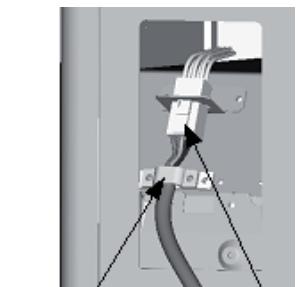
Cable clamp
Terminal


Periodic maintenance is essential for keeping your air conditioner efficient.

Before carrying out any maintenance, disconnect from the power supply by putting the installation on/off switch to "off".
INDOOR UNIT
Removing and cleaning the filter
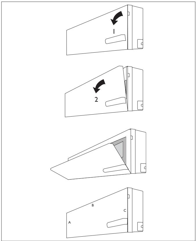
- Open the front panel following the direction of the arrow (1)
- Draw the front panel upwards
- Open the panel following the direction of the arrow (2)
- Keeping the front panel raised with one hand, take out the air filter with the other hand
- Clean the filter with water; if the filter is soiled with oil, it can be washed with warm water (not exceeding 45^ ). Leave to dry in a cool and dry place.
Installing the filter
- Keeping the front panel raised with one hand, insert the air filter with the other hand (see fig.)
- Insert the air filter
- Let the front panel slide downwards and ensure that the three catches (A, B and C) are properly inserted
- Close

The antibacterial silver ion filter and the biological deodoriser electrostatic filter (if installed) cannot be washed or regenerated. They must be replaced with new filters once every 6 months.
To replace, refer to the "Installation" section.
OUTDOOR UNIT

Use suitable instruments for the refrigerant R410A.

Do not use any other refrigerant than R410A.

Do not use mineral oils to clean the unit.
Note: the above figures may not correspond to the appearance of the units that have been purchased.
| Code | Error |
| E1 (*) | High pressure protection |
| E2 (*) | Defrost protection |
| E3 (*) | Low pressure protection |
| E4 (*) | Compressor gas discharge protection |
| E5 (*) | Current overload protection |
| E6 (*) | Communication malfunction |
| E7 (*) | MODE conflict |
| Code | Error |
| E8 (*) | High temperature protection |
| E9 (*) | Protection against cold air |
| F1 | Indoor unit room sensor disconnected |
| F2 | Indoor unit pipe sensor disconnected |
| F3 (*) | Outdoor unit ambient sensor disconnected |
| F4 (*) | Outdoor unit pipe sensor disconnected |
| F5 (*) | Outdoor unit delivery line sensor short-circuited/disconnected |
(*) Alarm codes valid only for DC INVERTER model
TROUBLESHOOTING
INSTALLATION
| Malfunction | Possible causes |
| ·The appliance does not operate | Power failure/Plug pulled out |
| Damaged indoor/outdoor unit fan motor | |
| Faulty compressor thermomagnetic circuit breaker | |
| Faulty protective device or fuses. | |
| Loose connections or plug pulled out | |
| It sometimes stops operating to protect the appliance. | |
| Voltage higher than 244V or lower than 206V | |
| Active TIMER-ON function | |
| Damaged electronic control board | |
| ·Strange odour | Dirty air filter |
| ·Noise of running water | Back flow of liquid in the refrigerant circuit |
| ·A fine mist comes from the air outlet | This occurs when the air in the room becomes very cold, for example in the “COOLING” or “DEHUMIDIFYING/DRY” modes. |
| ·A strange noise can be heard | This noise is made by the expansion or contraction of the front panel due to variations in temperature and does not indicate a problem. |
| ·Insufficient airflow, either hot or cold | Unsuitable temperature setting. |
| Obstructed air conditioner intakes and outlets. | |
| Dirty air filter. | |
| Fan speed set at minimum. | |
| Other sources of heat in the room. | |
| No refrigerant. | |
| ·The appliance does not respond to commands | Remote control not near enough to indoor unit. |
| The remote control batteries are dead. | |
| Obstacles between remote control and signal receiver on indoor unit. | |
| ·The control panel display is off | Active LIGHT function |
| Power failure | |
| Faulty control panel | |
| Faulty electronic control board | |
| ·Switch off the air conditioner immediately and cut off the power supply in the event of: | Strange noises during operation. |
| Faulty fuses or switches. | |
| Spraying water or objects inside the appliance. | |
| Overheated cables or plugs. | |
| Very strong smells coming from the appliance. |
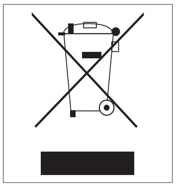
RECOMMENDATIONS FOR CORRECT DISPOSAL OF THE PRODUCT PURSUANT TO EUROPEAN DIRECTIVE 2002/96/EC
At the end of its useful life the product must not be disposed of together with municipal waste.
It may be taken to special centres for separately collected fractions set up by municipal authorities or to dealers that provide this service.
By disposing of a household electrical appliance separately, it is possible to avoid potential negative consequences for the environment and for health due to unsuitable disposal. It also allows the component materials to be recovered with consequent important saving of energy and resources.
To show the obligation to dispose of the household electrical appliances separately, the product bears the symbol of the crossed-out wheeled bin.
ENVIRONMENTAL INFORMATION
INSTALLATION
This unit contains fluorinated gases with greenhouse effect covered by the Kyoto Protocol. Maintenance and disposal must be carried out by qualified persons only.
Refrigerant gas R410A, GWP=1975.
USEFUL INFORMATION
For information on servicing and spare parts, please contact:
UFFICIO ASSISTENZA TECHNICA GRUPPO DE'LONGHI
Via L. Seitz, 47 - 31100 Treviso (ITALY)

In line with the company's policy of continual product improvement, the aesthetic and dimensional characteristics, technical data and accessories of this appliance may be changed without notice.
Cher Client,
INFORMATIONS GÉNÉRALES......Page
Conformité et gamme
KONFORMITÄT UND PRODUKTPALETTE
ALLGEMEINES
INSTALLATIE VAN DE BINNENUNIT
INSTALLATIE
- CONTENTS
- GENERAL INFORMATION
- GENERAL INFORMATION Page.
- USER
- INSTALLATION
- CONFORMITY AND RANGE
- NAMES OF THE PARTS
- REMOTE CONTROL
- Meaning of symbols on the liquid crystal display
- How to insert the batteries
- How to use the remote control
- Adjustment of horizontal airflow (manual)
- HEATING MODE
- SMART MODE
- Automatic mode
- Automatic switching-on
- Automatic switching-off
- DRY MODE
- Dehumidifying mode
- FAN MODE
- Night mode
- TURBO POWER FUNCTION
- I COMFORT FUNCTION
- LIGHT FUNCTION
- INSTALLING THE INDOOR UNIT
- LOCATING THE INDOOR UNIT
- Installing the mounting plate
- Drilling a hole in the wall for the piping
- Connecting the condensate outlet pipe
- Passing through the connections
- LOCATING THE OUTDOOR UNIT
- Floor standing
- Wall mounted
- Connecting the condensate drain hose
- INDOOR UNIT
- Removing and cleaning the filter
- Installing the filter
- OUTDOOR UNIT
- RECOMMENDATIONS FOR CORRECT DISPOSAL OF THE PRODUCT PURSUANT TO EUROPEAN DIRECTIVE 2002/96/EC
- ENVIRONMENTAL INFORMATION
- USEFUL INFORMATION
- INFORMATIONS GÉNÉRALES......Page
- KONFORMITÄT UND PRODUKTPALETTE
- ALLGEMEINES
- INSTALLATIE VAN DE BINNENUNIT
- INSTALLATIE
Brand : DELONGHI
Model : PLS120
Category : Heating