RL75iP - Boiler Rinnai - Free user manual and instructions
Find the device manual for free RL75iP Rinnai in PDF.

| Product Type | Instantaneous Gas Boiler (Tankless) |
| Brand | Rinnai |
| Model | RL75i (REU-VB2528FFUD-US) |
| Dimensions (H x W x D) | 780 x 521 x 350 mm |
| Weight | 34 kg |
| Power Supply | 120 V, 60 Hz, 15 A (3-prong grounded plug) |
| Gas Supply | Natural gas or propane (conversion by qualified technician) |
| Maximum Thermal Power | 199,000 BTU/h (58.3 kW) |
| Maximum Flow Rate | 7.5 GPM (28.4 L/min) |
| Temperature Range | 37 °C to 60 °C (extendable to 71 °C with MCC-91 controller) |
| Ignition Type | Automatic electronic (no pilot light) |
| Condensation | Yes (integrated condensate collector) |
| Venting | Direct vent, 4" (102 mm) diameter, certified materials |
| Gas Connections | 3/4" NPT |
| Water Connections | 3/4" NPT (cold inlet, hot outlet) |
| Main Functions | Instantaneous hot water production, electronic regulation, remote control priority |
| Safety | Freeze protection, overheat protection, flame detection, pressure relief valve |
| Maintenance | Annual filter cleaning, duct inspection, heat exchanger flush if LC code |
| Spare Parts | Available from the manufacturer (Rinnai) |
| Warranty (Domestic Use) | Heat exchanger: 12 years, Parts: 5 years, Labor: 1 year |
| Installation | Indoor only, by qualified technician |
Frequently Asked Questions - RL75iP Rinnai
User questions about RL75iP Rinnai
0 question about this device. Answer the ones you know or ask your own.
Ask a new question about this device
Download the instructions for your Boiler in PDF format for free! Find your manual RL75iP - Rinnai and take your electronic device back in hand. On this page are published all the documents necessary for the use of your device. RL75iP by Rinnai.
USER MANUAL RL75iP Rinnai
Direct Vent Tankless Water Heater
Operation and Installation Manual
natural_image
Line drawing of a gas washing machine (no text or symbols)
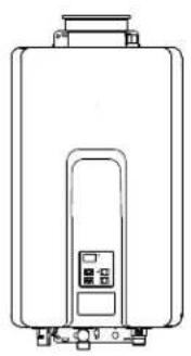
natural_image
Front view line drawing of a rectangular electronic device with a small control panel and two top-mounted ports (no text or symbols)RL75i.... REU-VB2528FFUD-US
RL94i.... REU-VB2735FFUD-US
R98LSi....REU-VA3237FFU-US
R98LSi-ASME .... REU-VA3237FFU-ASME
The VB series (RL75i, and RL94i) are certified for installation in manufactured (mobile) homes.
Register your product at www.rinnairegistration.com or call 1-866-RINNAI1 (746-6241)


ANS Z21.10.3
CSA 4.3
FOR INDOOR APPLICATIONS ONLY
Table of Contents ...... 2
Consumer Safety Information ... 4
Operating Instructions ......6
Maintenance 11
Error Codes 12
Installation Instructions ..... 16
Consumer Support 44
French Version 47
INSTALLER: Leave this manual with the appliance.
CONSUMER: Retain this manual for future reference.
WARNING
If the information in these instructions is not followed exactly, a fire or explosion may perty damage, personal injury or death.
— Do not store or use gasoline or other flammable vapors and liquids in the vicinity of this or any other appliance.
— WHAT TO DO IF YOU SMELL GAS
- Do not try to light any appliance.
- Do not touch any electrical switch; do not use any phone in your building.
- Immediately call your gas supplier from a neighbor's phone. Follow the gas supplier's instructions.
- If you cannot reach your gas supplier, call the fire department.
— Installation and service must be performed by a qualified installer, service agency or the gas supplier.
California Proposition 65 lists chemical substances known to the state to cause cancer, birth defects, death, serious illness or other reproductive harm. This product may contain such substances, be their origin from fuel combustion (gas, oil) or components of the product itself.
Table of Contents
Specifications 3
Consumer Safety Information
Safety Definitions....4
Safety Behaviors and Practices......4
Safety Features....4
Description of Operation.
Operating Instructions
Temperature Controller....5
Features Available on Temperature
Controllers....6
How to Set the Temperature 7
Temperature Controller Settings....7, 8
Temperature Options Without a Temperature Controller....8
Setting the Sound Volume (Voice Prompt)..... 8
Using the Water Smart / Bath Fill Function ..... 9
Overview 9
Setting the Water Volume 9
Filling the Tub....10
Setting Controller to Mute....10
Setting the Clock....10
Maintenance Cleaning 11
Vent System 11
Motors 11
Temperature Controller 11
Lime / Scale Build-up 11
Snow Accumulation 11
Visual Inspection of Flame 11
Error Codes
Error Code Table 12,13
Trouble Shooting for Common Issues ...... 14
Accessing Operating Information.... 14
Water Quality 14
Flushing the Heat Exchanger
(Error Code: LC or 00)....15
Installation Instructions 16
General Instructions 16
Clearances from Appliance 17
Attachment of the Water Heater 17
Electrical Connection....18
Error Indication or Air Handler Control Switch...
(RL75i, RL94i only).... 18
Gas Piping
General Instructions 18
Pipe Sizing Procedure - Example ...... 19
Water Piping
Isolation Valves and Pressure Relief Valves 20
Piping Requirements 21
Pressure Relief Valve Requirements ..... 21
Freeze Protection 21, 22
Freeze Protection Piping 23
Recommended Piping for Basic Installation ..24
Recommended Piping for Circulation Systems....25
Venting Instructions Intake / Exhaust Guidelines .... 26
Condensate 26
Maximum Vent Length 27
Vent Products 28
Flue Terminal Clearances
(ANS Z21.10.3, CSA 4.3) 29
Additional Clearances - Vent Terminal ...... 30
Flue Installation - Concentric Venting (RL75i, RL94i) 31
Flue Installation (R98LSi, R98LSi-ASME).... 32, 33
Connecting Multiple Water Heaters....34
High Altitude Installations 34, 35
Temperature Controller Installation Location 36
Configurations....36
Cable Lengths and Size 36
Mounting the Controller 37
Operating Instructions 38
Technical Data
Pressure Drop Curve 39
Outlet Flow Data 39
Space Heating 40
Dimensions 41
Ladder Diagrams 42, 43
Consumer Support
Warranty Information 44
Limited Warranty.... 44, 45
State Regulations....46
French Version 47-68
| Specifications | |||||
| Model | RL75i | RL94i | R98LSi | R98LSi-ASME | |
| Minimum Gas Consumption Btu/h | 9,900 (NG)10,300 (LPG) | 19,000 | |||
| Maximum Gas Consumption Btu/h 180,000 | 199,000 (NG)190,000 (LP) | 237,000 | |||
| Hot water capacity (Min - Max) * | 0.4 - 7.5 GPM(1.5 - 28.5 L/min) | 0.4 - 9.4 GPM(1.5 - 35.5 L/min) | 0.6 - 9.8 GPM(2.4 - 37 L/min) | ||
| Hot water capacity (45°F rise) | 6.6 GPM(25.0 L/min) | 7.1 GPM(27.0 L/min) | 8.5 GPM(32.2 L/min) | ||
| Default Temperature Setting (no controller) 120°F (49°C) | |||||
| Temperature Controller Default Setting 104°F (40°C) | |||||
| Maximum Temp Setting (commercial **) 160°F (71°C) | 185°F (85°C) | ||||
| Maximum Temp Setting (residential)see Temperature Ranges for more information | Selectable at 120°F (49°C) or at 140°F(60°C) | 140°F (60°C) | |||
| Minimum Temperature Setting 98°F (37°C) | |||||
| Weight 51 lb (23 kg) 53 lb (24 kg) 55 lb (25 kg) | |||||
| Efficiency Thermal Efficiency: 84.0% | Energy Factor: 0.82 | ||||
| Noise level 49 dB | |||||
| Electrical Consumption | Normal 76 W | 83 W | 99 W | ||
| Standby | 2 W | ||||
| Anti-frost Protection | 184 W | 116 W | |||
| By-Pass Control | Fixed | Electronic | |||
| Minimum Gas SupplyPressure | Natural Gas | 5.0 inch W.C. | |||
| Propane | 8.0 inch W.C. | ||||
| Maximum Gas SupplyPressure | Natural Gas 10.5 inch W.C. | ||||
| Propane | 13.5 inch W.C. | ||||
| Type of Appliance | Direct Vent, Temperature controlled continuous flow gas hot water system. | ||||
| Operation | With or without remote controls, mounted in kitchen, bathroom, etc. | ||||
| Approved Gas Type | Natural Gas or Propane - Ensure unit matches gas type supplied at the installation | ||||
| Connections | Gas Supply: 3/4" MNPT, Cold Water Inlet: 3/4" MNPT, Hot Water Outlet: 3/4" MNPT | ||||
| Ignition System | Direct Electronic Ignition | ||||
| Electric Connections | Appliance: AC 120 Volts, 60Hz. Remote Control: DC 12 Volts (Digital) | ||||
| Water Temperature Control | Simulation Feedforward and Feedback. | ||||
| Water Supply Pressure | Minimum Water Pressure: 20 PSI (Recommended 30-80 PSI for maximum | ||||
| Maximum Water Supply Pressure | 150 PSI | ||||
| Remote Control Cable | Non-Polarized Two Core Cable (Minimum 22 AWG) | ||||
| Energy Star Qualified | Yes | Yes | No (not applicable) | ||
| Certified for installation in manufactured (mobile)homes | Yes Yes | No | No | ||
* Minimum flow may vary slightly depending on the temperature setting and the inlet water temperature.
** for commercial and hydronic applications requiring higher temperatures
Rinnai is continually updating and improving products. Therefore, specifications are subject to change without prior notice.
The maximum inlet gas pressure must not exceed the value specified by the manufacturer. The minimum value listed is for the purpose of input adjustment.
VB Series Indoor LS Manual 3
Consumer Safety Information
Safety Definitions

This is the safety alert symbol. This symbol alerts you to potential hazards that can kill or hurt you and others.

DANGER
Indicates an imminently hazardous situation which, if not avoided, will result in death or serious injury.

WARNING
Indicates a potentially hazardous situation which, if not avoided, could result in death or serious injury.

CAUTION
Indicates a potentially hazardous situation which, if not avoided, could result in minor or moderate injury. It may also be used to alert against unsafe practices.
Safety Behaviors and Practices

WARNING
- Keep the area around the appliance clear and free from combustible materials, gasoline, and other flammable vapors and liquids.
- Any alteration to the appliance or its controls can be dangerous and will void the warranty.
- Always check the water temperature before entering a shower or bath.
- Do not use this appliance if any part has been under water. Immediately call a qualified service technician to inspect the appliance and to replace any part of the control system and any gas control which has been under water.
Safety Features
- Overheat: The appliance will automatically shut down when the appliance exceeds a predetermined temperature.
- Flame Failure: The appliance will automatically shut down if the burner flame is not adequate.
-
Power Failure: The appliance will cut off the gas if it loses electrical power.
-
Power Surge Fuse: A glass fuse protects against overcurrent. If the fuse blows then all indicator lamps will be off.
- Fusible Link: In case the overheat feature does not prevent the temperature from rising then the fusible link will break shutting off the appliance.
Description of Operation
The Rinnai water heater is one of the most advanced water heaters available. It provides a continuous supply of hot water at a preset temperature. This appliance is direct vent where air is brought in from the outside and combustion gases are exhausted to the outside.
While electricity, water, and gas supplies are connected, the Rinnai water heater produces hot water whenever a hot water tap is open.
Ignition is electronic. There is no pilot light consuming gas while the water heater is not being used. The gas burner lights automatically when the hot water tap is opened and goes out when the tap is closed.
Installation of the temperature controller is highly recommended. The temperature controller can set the temperature within a specific range and can provide error codes to diagnose any problems.
The temperature of the outgoing hot water is constantly monitored. The Rinnai water heater may adjust the water flow in order to maintain the temperature setting. The water flow may vary from summer to winter due to the difference in ground water temperature.
MC-91-1US & MCC-91-1US
Dimensions (inches): 3.5 W x 4.75 H x 0.75 D
The MC-91 controller is the standard temperature controller that is supplied with the water heater. On indoor models it is integrated into the front panel. The MCC-91 controller is for commercial and hydronic applications requiring higher temperatures. When the MCC-91 controller is connected, these higher temperatures are available on all controller models in the system. Refer to the section on temperature ranges.

flowchart
graph TD
    A["In Use Indicator"] --> B["Approx Water Temp"]
    C["Temperature Display"] --> B
    D["Temperature Selection"] --> B
    B --> E["MC-91-1US"]
    B --> F["F/C"]
    B --> G["Priority"]
    B --> H["Priority Button"]
    B --> I["On/Off Button"]
    B --> J["Rinnai"]
    style B fill:#f9f,stroke:#333
Operating Instructions
The MC-91 temperature controller is supplied with the RL75, RL94, and R98LS models. Additional functions are available through the use of optional controllers.
There are several models of temperature controllers that can be purchased separately. Their description, operation, and installation is provided in this manual in case additional temperature controllers are purchased and installed.
Features Available on Temperature Controllers
| Features | MC-91 | MCC-91 | MC-100 | BC-100 | MC-502 | Description |
| Call | ● | ● | Sends a short series of beeps to all controllers in the system. It is not an intercom. | |||
| Clock | ● | ● | 12 hour AM/PM clock. (The MC-100 must be installed for clock to work on the BC-100.) | |||
| Error Codes | ● | ● | ● | ● | ● | When a fault is detected an error code flashes at the temperature display on models MC-91, MCC-91, and MC-502; and flashes at the clock display on models MC-100 and BC-100. |
| Function | ● | Used on this model to set the clock or sound volume. | ||||
| In Use Indicator | ● | Indicates that hot water is being supplied (i.e. a hot water tap is open). | ||||
| ON/OFF Button | ● | Used to turn the water heater ON or OFF. | ||||
| Power Save | ● | ● Allows the temperature controller to be in an energy saving mode. | ||||
| Priority Button / Indicator | ● | ● | ● | ● | ● | Indicates that this controller is setting the temperature . Priority can be switched to another controller by pressing its Priority Button when no hot water is running. |
| Sound Volume | Used to adjust the voice prompt volume. | |||||
| Temperature Display | ● | Shows the temperature setting. | ||||
| Thermostat | ● | Increases or decreases the temperature setting. | ||||
| Water Smart / Bath Fill Button / Indicator | Used to select the Water Smart / Bath Fill Function to fill a bath with a predetermined volume of water. | |||||
| Water Volume | Used to select the water volume for the Water Smart / Bath Fill Function. | |||||

text_image
DANGER HOT BURNHot water can be dangerous, especially for infants or children, the elderly, or infirm. There is hot water scald potential if the thermostat is set too high.
Water temperatures over 125^ F ( 52^ C) can cause severe burns or scalding resulting in death.
Hot water can cause first degree burns with exposure for as little as:
3 seconds at 140^ F ( 60^ C)
20 seconds at 130°F (54°C)
8 minutes at 120^ F ( 49^ C)
Test the temperature of the water before placing a child in the bath or shower.
Do not leave a child or an infirm person in the bath unsupervised.

-
If the water heater is off, press the ON/OFF button to turn on.
-
Press the "Priority button" on the temperature controller. The green Priority light will glow indicating that this controller is controlling the temperature and that the Rinnai water heater is ready to supply hot water.
The priority can only be changed while no hot water is running.

- Press the ▲ or ▼ buttons to obtain the desired temperature setting.

*All hot water sources are able to provide water at this temperature setting until it is changed again at this or another temperature controller.
| NOTICE | While any hot water is being provided, the temperature setting can only be adjusted between 98°F and 110°F. |
| NOTICE | Check local codes for the maximum water temperature setting allowed when used in nursing homes, schools, day care centers, and all other public applications. |
| NOTICE | If a newly installed unit with a controller has not been powered for at least 6 hours then the temperature will return to the default setting of 104°F (40°C) if power is interrupted. |
| NOTICE | There may be a variation between the temperature displayed on the temperature controller and the temperature at the tap due to weather conditions or the length of pipe to the water heater. |
Temperature Controller Settings
This water heater will attempt to provide hot water at the temperature setting even when the water flow is varied or when more than 1 tap is in use. The water heater can deliver water at only one temperature setting at a time. The available temperatures for a given model are provided below.
| Model | Temperature Settings Available (°F) | ||||||||||||||||
| RL75i | 98 | 100 | 102 | 104 | 106 | 108 | 110 | 115 | 120 | 125* | 130* | 135* | 140* | 150** | 160** | ||
| RL94i | 98 | 100 | 102 | 104 | 106 | 108 | 110 | 115 | 120 | 125* | 130* | 135* | 140* | 150** | 160** | 185** | |
| R98LSi R98LSi-ASME | 98 | 100 | 102 | 104 | 106 | 108 | 110 | 115 | 120 | 125 | 130 | 135 | 140 | 150** | 160** | 185** | |
| Temp in Celsius °C | 37 38 | 39 | 40 41 | 42 43 | 46 49 | 52 | 54 57 | 60 | 66 71 | 85 | |||||||
An older controller, MC-45, can be installed with the RL75i and RL94i by moving switch No. 6 in the bank of 6 switches to ON. Some of the temperature settings will be slightly different from the above table.
Temperature Controller Settings
\* Re-setting the Maximum Temperature (RL75 and RL94 only)
Models RL75 and RL94 have a default maximum temperature of 120^ F ( 49^ C) and an option to increase the maximum temperature to 140^ F ( 60^ C). Temperature settings from 125-140^ F ( 52-60^ C) are available by setting switch 6 to ON in the SW1 bank of 8 switches.
\*\* MCC-91 Temperature Controller
These settings require the MCC-91 controller. When the MCC-91 controller is connected, these higher temperatures are available on all controller models in the system. Use of an MCC-91 controller in a residential dwelling will reduce the warranty coverage to that of a commercial warranty application.
The MCC-91 controller is intended for commercial and hydronic applications only. If an MCC-91 controller is used in a residential dwelling for a hydronics application, a mixing valve must also be installed to limit the potable hot water temperature to a safe temperature. Water temperatures over 125^ F ( 52^ C) can cause severe burns or scalding. Refer to the Danger Alert on water temperatures. Rinnai shall not, in any event, be liable for damages resulting from such misuse or misapplication.
Maximum Temperature
120^(49^) 140^(60^)

text_image
Switch No. ON OFF 1 2 3 4 5 6 7 8 Switch No. ON OFF 1 2 3 4 5 6 7 8
WARNING
DO NOT adjust the other switches unless specifically instructed to do so.
Suggested temperatures are
- Kitchen 120 °F (49° C)
• Shower 98 - 110 °F (37 - 43 °C)
• Bath Fill 102 - 110 °F (39 - 43 °C)
These temperatures are suggestions only.
A temperature lower than 98^ F ( 37^ C) can be obtained at the tap by mixing with cold water.
To change the temperature scale from Celsius to Fahrenheit or vice versa, press and hold the "On/Off" button for 5 seconds while the water heater is OFF.
Temperature Options Without a Temperature Controller
The default temperature setting for this appliance installed without a temperature controller is 120^ F ( 49^ C). If desired, the temperature setting can be changed to 140^ F ( 60^ C) by adjustment of a switch.
In the SW1 bank of 8 switches, set switch 5 to ON to obtain 140^ F water temperature setting. Set switch 5 to OFF (default) to obtain 120^ F water temperature setting.
If a temperature controller is installed, then switch 5 has no effect on temperature settings.
Setting the Sound Volume (Voice Prompt)

MC-100V Press the "Function" button to adjust the voice prompt volume. The default sound volume is set to Medium. Each subsequent press of the ▲ or ▼ button cycles through the volume levels in the order below.

BC-100V Press the "Sound Vol." button to adjust the voice prompt volume. The default sound volume is set to Medium. Each subsequent press of the button cycles through the volume levels in the order below.

flowchart
graph LR
    A["Medium Volume (default)"] --> B["High Volume"]
    B --> C["Off Volume (beep)"]
    C --> D["Off Sound (no beep)"]
    D --> E["Low Volume"]
    E --> A
8 VB Series Indoor LS Manual
Overview
This function is exclusive to the BC-100V temperature controller. The bath fill function allows the consumer to fill a tub with a preset volume of water at a preset temperature. This is done by pressing the bath fill button on the BC-100V controller while no hot water is flowing and then opening only the hot water tap. The water heater will stop the hot water flow when the preset volume has been reached. The hot water tap should then be closed and the bath fill button pressed.
The temperature settings for the bath fill function are limited to those in the table below.
| Bath Fill Temperature Settings Available | |||||||
| °F | 98 | 100 | 102 | 104 | 106 | 108 | |
| °C | 37 | 38 | 39 | 40 | 41 | 42 | |
| °F | 110 | 112 | 114 | 116 | 118 | 120 | |
| °C | 43 | 44 | 46 | 47 | 48 | 49 | |
NOTICE
Multiple Water Heaters
The bath fill function will not work properly if it is connected to multiple water heaters. The tub will overfill because the bath fill function is not able to measure the water volume when connected to multiple water heaters.
NOTICE
If power is lost during the bath fill function, the water heater will shut down but the water will continue to flow. When power returns, the water shuts off and Error Code 03 appears on the controller.
Power Loss
If power is lost after the bath has filled but before the bath fill function button is de-selected, then the water will not flow during the power loss or after the power is returned. Once power returns, close the hot water tap and de-select the bath fill function. No error code appears.
NOTICE
Do not use with single handle fixtures that have anti-scald features built into them. These fixtures allow a predetermined amount of cold water which is not taken into account by the bath fill function.
Setting the Water Volume
The default volume is set to 25 gallons. The volume can be set between 10 and 120 gallons.

- Press the "Priority" button on the temperature controller. The green Priority light will glow indicating that this controller is controlling the temperature and that the Rinnai water heater is ready to supply hot water.
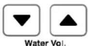
- Press the "Water Vol." ▲ or ▼ buttons to obtain the desired water volume in gallons.

- Press the "Water Smart Bath Fill" button.

- Press the "Water Smart Bath Fill" button to set the water volume and temperature.
NOTICE
Be careful not to overfill the bath. An average bath volume is 60 gallons. When filling the bath using this function for the first time:

- Press the "Temp" ▲ or ▼ buttons to obtain the desired temperature setting.
To Prevent Over Filling
- Monitor and remain by the bath while the water is running. - Use a low bath fill volume less than 25 gallons
Filling the Tub


-
Press the "Water Smart / Bath Fill" button once. The button will illuminate, and a tone will sound.
-
The voice prompt will announce "The hot water system is ready. Open the hot water tap." Make sure the water volume is set. Refer to "Setting the Water Volume" on the previous page. Open the hot water tap. The "In Use" indicator will illuminate on MC-100V and BC-100V controllers. The hot water will begin to flow.
-
When the preset volume of water has been produced then
•the water flow will cease
- the "Water Smart / Bath Fill" button will flash
- a tone will sound
- the voice prompt will announce, "Bath fill is complete. Turn off the bath hot water tap and push the Bath Fill button."
- Turn off the bath hot water tap and push the Bath Fill button. The water heater will not allow hot water to flow from any source until the "Water Smart / Bath Fill" button is pushed. The button light will go out.
NOTICE
To stop the water flow during the Bath Fill function, press the "Water Smart / Bath Fill" button. The button will flash and the voice prompt will announce, "Hot water is not available. Turn off all hot water taps and push the Bath Fill button." Follow the voice prompt instructions.
To Stop the Bath Fill Before it Finishes
NOTICE
During the bath fill function, any hot water flowing at other locations, subtracts from the total amount of water for the bath. For example if the bath fill function is set for 50 gallons and 5 gallons of hot water are used at other locations during the fill period then the bath will only fill with 45 gallons.
When Other Taps Are Open
NOTICE
During the operation of the bath fill function, the MC-91 "In Use" indicator does not light up.
Setting Controller to Mute
Models MC-91 and MCC-91
To eliminate the beeps when keys are pressed or to turn the beeps back on, press and hold both the ▲ and ▼ buttons until a beep is heard (approximately 5 seconds).
Setting the Clock

MC-100V Press the "Function" button twice within 10 seconds to set the clock. Press the ▲ or ▼ button to reach the desired time. The clock on the BC-100V automatically shows the time which has been set on the MC-100V.

WARNING
Turn off the electrical power supply, the manual gas valve and the manual water control valve whenever servicing the unit.
Repairs and maintenance should be performed by a qualified service technician. The appliance should be inspected annually by a qualified service technician. Verify proper operation after servicing.
Cleaning
It is imperative that control compartments, burners, and circulating air passageways of the appliance be kept clean.
Clean as follows:
- Turn off and disconnect electrical power. Allow to cool.
- Close the water shut off valves. Remove and clean the water inlet filter.
- Remove the front panel by removing 4 screws.
- Use pressurized air to remove dust from the main burner, heat exchanger, and fan blades. Do not use a wet cloth or spray cleaners on the burner. Do not use volatile substances such as benzene and thinners. They may ignite or fade the paint.
- Use soft dry cloth to wipe cabinet.
Vent System
The vent system should be inspected at least annually for blockages or damage.
Motors
Motors are permanently lubricated and do not need periodic lubrication. Keep fan and motor free of dust and dirt by cleaning annually.
Temperature Controller
Use a soft damp cloth to clean the temperature controller. Do not use solvents.
Lime / Scale Build-up
If you receive Error Code "LC", refer to the procedure, Flushing the Heat Exchanger. Refer to the section on Water Quality to see if your water needs to be treated or conditioned. (When checking maintenance code history, "00" is substituted for "LC".)
Snow Accumulation
Keep the area around flue terminal free of snow and ice. The appliance will not function properly if the intake air or exhaust is impeded (blocked or partially blocked) by obstructions.
Visual Inspection of Flame
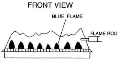
The burner must flame evenly over the entire surface when operating correctly. The flame must burn with a clear, blue, stable flame. See the parts breakdown of the burner for the location of the view ports.
The flame pattern should be as shown in the figures below.
SATISFACTORY
text_image
FRONT VIEW BLUE FLAME FLAME RODUNSATISFACTORY

text_image
FRONT VIEW YELLOW FLAME FLAME RODError Codes
The Rinnai water heater has the ability to check its own operation continuously. If a fault occurs, an error code will flash on the display of the temperature controller. This assists with diagnosing the fault and may enable you to overcome a problem without a service call. Please identify the code displayed when inquiring about service.

WARNING
Some of the checks below may need to be done by a qualified service technician. Call a service technician for any remedy that involves gas or electricity. Call a service technician if you have any doubt or reservation about performing the remedy yourself.
| Code | Fault | Remedy |
| 02 | No burner operation during freeze protection mode | Service Call |
| 03 | Power interruption during Bath Fill (Water will not flow when power returns). | Turn off all hot water taps. Press ON/OFF twice. |
| 10 | Air Supply or Exhaust Blockage | Ensure Rinnai approved venting materials are being used.Check that nothing is blocking the flue inlet or exhaust.Check all vent components for proper connections.Ensure vent length is within limits.Ensure condensation collar was installed correctly.Verify dip switches are set properly.Check fan for blockage. |
| 11 | No Ignition | Check that the gas is turned on at the water heater, gas meter, or cylinder.Ensure gas type and pressure is correct.Ensure gas line, meter, and/or regulator is sized properly.Bleed all air from gas lines.Verify dip switches are set properly.Ensure appliance is properly grounded.Disconnect EZConnectTM or MSA controls to isolate the problem.Ensure igniter is operational.Check igniter wiring harness for damage.Check gas solenoid valves for open or short circuits.Remove burner cover and ensure all burners are properly seated.Remove burner plate and inspect burner surface for condensation or debris. |
| 12 | Flame Failure | Check that the gas is turned on at the water heater and gas meter. Check for obstructions in the flue outlet.Ensure gas line, meter, and/or regulator is sized properly.Ensure gas type and pressure is correct.Bleed all air from gas lines.Ensure proper Rinnai venting material was installed.Ensure condensation collar was installed properly.Ensure vent length is within limits.Verify dip switches are set properly.Ensure appliance is properly grounded.Disconnect keypad.Disconnect EZConnectTM or MSA controls to isolate the problem.Check power supply for loose connections.Check power supply for proper voltage and voltage drops.Ensure flame rod wire is connected.Check flame rod for carbon build-up.Disconnect and reconnect all wiring harnesses on unit and PC board.Check for DC shorts at components.Check gas solenoid valves for open or short circuits.Remove burner plate and inspect burner surface for condensation or debris.Check the ground wire for the PC board. |
Error Codes
| Code | Fault | Remedy |
| 14 | Thermal Fuse Check gas | type of unit and ensure it matches gas type being used.Check for restrictions in air flow around unit and vent terminal.Check for low water flow in a circulating system causing short-cycling.Ensure dip switches are set to the proper position.Check for foreign materials in combustion chamber and/or exhaust piping.Check heat exchanger for cracks and/or separations.Check heat exchanger surface for hot spots which indicate blockage due to scale build-up.Refer to instructions in manual for flushing heat exchanger.Measure resistance of safety circuit.Ensure high fire and low fire manifold pressure is correct.Check for improper conversion of product. |
| 16 | Over Temperature Warning | Check for restrictions in air flow around unit and vent terminal.Check for low water flow in a circulating system causing short-cycling.Check for foreign materials in combustion chamber and/or exhaust piping.Check for clogged heat exchanger. |
| 31 | Burner Sensor Error Measure resistance of sensor.Replace sensor. | |
| 32 | Outgoing Water Temperature Sensor Fault | Check sensor wiring for damage.Measure resistance of sensor.Clean sensor of scale build-up.Replace sensor. |
| 33 | Heat Exchanger Outgoing Temperature Sensor Fault | Check sensor wiring for damage.Measure resistance of sensor.Clean sensor of scale build-up.Replace sensor. |
| 34 | Combustion Air Temperature Sensor Fault | Check for restrictions in air flow around unit and vent terminal.Check sensor wiring for damage.Measure resistance of sensor.Clean sensor of scale build-up.Ensure fan blade is tight on motor shaft and is in good condition.Replace sensor. |
| 52 | Modulating Solenoid Valve Signal Abnormal | Check modulating gas solenoid valve wiring harness for loose or damaged terminals.Measure resistance of valve coil. |
| 61 | Combustion Fan Failure Ensure fan will turn freely.Check wiring harness to motor for damaged and/or loose connections.Measure resistance of motor winding. | |
| 65 | Water Flow Control Fault | The water flow control valve has failed to close during the bath fill function. Immediately turn off the water and discontinue the bath fill function. Contact a state qualified or licensed contractor to service the appliance. |
| 71 | Solenoid Valve Circuit Fault | Replace the PC Board. |
| 72 | Flame Sensing Device Fault | Ensure flame rod is touching flame when unit fires.Check all wiring to flame rod for damage.Remove flame rod and check for carbon build-up; clean with sand paper.Check inside burner chamber for any foreign material blocking flame at flame rod.Measure micro amp output of sensor circuit with flame present.Replace flame rod. |
| 73 | Burner Sensor Circuit Error | Check sensor wiring and PC board for damage.Replace sensor. |
| LC | Scale Build-up in Heat Exchanger (when checking maintenance code history, "00" is substituted for "LC") | Flush heat exchanger. Refer to instructions in manual.Replace heat exchanger.NOTE: The LC code is the only error code that will allow the unit to keep running. The display will alternate between the LC code and the temperature setting. The controller will continue to beep. The LC code will reset if power is turned off and then on. |
| No code | Nothing happens when water flow is activated. | Clean inlet water supply filter.On new installations ensure hot and cold water lines are not reversed.Check for bleed over. Isolate unit from building by turning off cold water line to building.Isolate the circulating system if present. Open your pressure relief valve; if water is flowing, there is bleed over in your plumbing.Ensure you have at least the minimum flow rate required to fire unit.Ensure turbine spins freely.Measure the resistance of the water flow control sensor.Check for DC shorts at components. |
I don't have any hot water when I open the tap.
Make sure there is gas, water, and electricity to the Rinnai water heater (power is turned on and the gas is turned on).
When I was using the hot water, the water got cold.
If you adjusted the flow from the tap to lessen it, you may have gone below the minimum flow required. The Rinnai water heater requires a minimum flow rate to operate. (See the specification page for the flow rate of your model.)
If you are experiencing issues with higher temperature settings, then Rinnai recommends reducing the temperature setting. Selecting a temperature closer to that which is actually used at the faucet will increase the amount of hot water being delivered to the faucet, due to less cold water mixing at the fixture.
White smoke comes out of the exhaust.
During colder weather when the exhaust temperature is much hotter than the outside air, the exhaust fumes condense producing water vapor.
When I open a hot tap, I do not immediately get hot water.
Hot water must travel through your plumbing from the Rinnai water heater to the faucet. The time period for hot water to reach your fixture is determined by the amount of water in the plumbing system between the water heater and the fixture, water pressure, and the flow rate of the fixture.
After I turn off the hot water tap, the fan on the Rinnai water heater continues to run.
The fan is designed to continue running for a short time after the flow of water stops. This is to ensure constant water temperatures during rapid starting and stopping, as well as exhausting any residual gas flue products from the unit.
Accessing Operating Information
Models MC-91 and MCC-91
To display the most recent error codes press and hold the "On/Off" button for 2 seconds. While holding the "On/Off" button press the ▲ button. The last 9 error codes will flash one after the other. To exit this mode press the "On/Off" and ▲ button as before.
To display the water flow through the water heater press and hold the ▲ button for 2 seconds and without releasing the ▲ button press the "On/Off" button.
To display the outlet water temperature press and hold the ▼ button for 2 seconds and without releasing the ▼ button press the "On/Off" button.
Water Quality
Consideration of care for your water heater should include evaluation of water quality. If the water quality exceeds the target levels provided in the table, you may want to treat or condition the water.
* Source: Part 143 National Secondary Drinking Water Regulations
| Maximum Level | |
| Total Hardness Up to 200 | mg / L |
| Aluminum * Up to 0.2 mg / L | |
| Chlorides * Up to 250 mg / L | |
| Copper * Up to 1.0 mg / L | |
| Iron * Up to 0.3 mg / L | |
| Manganese * Up to 0.05 mg / L | |
| pH * 6.5 to 8.5 | |
| TDS (Total Dissolved Solids) * | Up to 500 mg / L |
| Zinc * Up to 5 mg / L |
An “LC” or “00” error code indicates the unit is beginning to lime up and must be flushed. Failure to flush the appliance will cause damage to the heat exchanger. Damage caused by lime build-up is not covered by the unit's warranty. After flushing, reset the LC fault code by turning off the power to the unit and turning the power back on.
- Disconnect electrical power to the water heater.
- Close the shutoff valves on both the hot water and cold water lines (V3 and V4).
-
Connect pump outlet hose (H1) to the cold water line at service valve (V2).
-
Connect drain hose (H3) to service valve (V1).
-
Pour 4 gallons of undiluted virgin, food grade, white vinegar into pail.
-
Place the drain hose (H3) and the hose (H2) to the pump inlet into the cleaning solution.
-
Open both service valves (V1 and V2) on the hot water and cold water lines.
-
Operate the pump and allow the cleaning solution to circulate through the water heater for 1 hour at a rate of 4 gallons per minute (15.1 liters per minute).
-
Turn off the pump.
-
Rinse the cleaning solution from the water heater as follows:
a. Remove the free end of the drain hose (H3) from the pail.
b. Close service valve, (V2), and open shutoff valve, (V4). Do not open shutoff valve, (V3).
c. Allow water to flow through the water heater for 5 minutes
d. Close service valve, (V1), and open shutoff valve, (V3).
- Disconnect all hoses.
-
With (V4) closed, remove the in-line filter at the cold water inlet and clean out any residue. Place filter back into unit and open (V4).
-
Restore electrical power to the water heater.
CLEAN THERMISTORS
Remove and clean thermistors with a soft cloth or sponge after removing O-rings.
Cleaning solution is 4 gallons of undiluted virgin, food grade, white vinegar.
KEY

text_image
3/4" Ball Valve 3/4" Union Check Valve Pressure Relief Valve Pressure Regulator Circulating Pump Boiler Drain Valve Solenoid Valve
flowchart
graph TD
    A["Rinnai Water Heater"] --> B["Hot Water Line"]
    A --> C["Circulating Pump"]
    B --> D["V1"]
    B --> E["V2"]
    B --> F["V3"]
    B --> G["V4"]
    C --> H["H1"]
    C --> I["H2"]
    C --> J["H3"]
    style A fill:#f9f,stroke:#333
    style B fill:#ccf,stroke:#333
    style C fill:#cfc,stroke:#333
    style D fill:#fcc,stroke:#333
    style E fill:#fcc,stroke:#333
    style F fill:#fcc,stroke:#333
    style G fill:#fcc,stroke:#333
    style H fill:#cff,stroke:#333
    style I fill:#cff,stroke:#333
    style J fill:#cff,stroke:#333
Installation Instructions
Only properly trained and qualified installers should install this appliance. The warranty may be voided due to improper installation or installation by a non-qualified installer.
Rinnai highly recommends all installers attend a product knowledge class.
For information on a Rinnai Training Course or for questions on installation call 1-800-621-9419.
RL75i.... REU-VB2528FFUD-US
RL94i...... REU-VB2735FFUD-US
R98LSi......REU-VA3237FFU-US
R98LSi-ASME .... REU-VA3237FFU-ASME
The VB series (RL75i, and RL94i) are certified for installation in manufactured (mobile) homes.
General Instructions

WARNING
Do not use substitute materials.
Use only parts certified with the appliance.
- This appliance must be installed by a state qualified or licensed contractor. It is the responsibility of the person having the water heater installed to ensure the installing contractor has proper licenses and permits for installing water heaters in your location. Rinnai highly recommends that installers attend a product knowledge class to ensure customer satisfaction and warranty coverage. Failure to comply with state and local codes pertaining to water heater installations may void the warranty.
- This appliance is not to be installed outdoors.
- A qualified installer or service technician should install the appliance, inspect it, and leak test it before use.
- The installation must conform with local codes or, in the absence of local codes, with the National Fuel Gas Code, ANSI Z223.1/NFPA 54, or the Natural Gas and Propane Installation Code, CSA B149.1. If installed in a manufactured home, the installation must conform with the Manufactured Home Construction and Safety Standard, Title 24 CFR, Part 3280 and/or CAN/SCA Z240 MH Series, Mobile Homes.
- The appliance, when installed, must be electrically grounded in accordance with local codes or, in the absence of local codes, with the National Electrical Code, ANSI/NFPA 70, or the Canadian Electrical Code, CSA C22.1.
-
The appliance and its appliance main gas valve must be disconnected from the gas supply piping system during any pressure testing of that system at test pressures in excess of 1/2 psi (3.5 kPa) (13.84 in W.C.).
-
The appliance must be isolated from the gas supply piping system by closing its individual manual shutoff valve during any pressure testing of the gas supply piping system at test pressures equal to or less than 1/2 psi (3.5 kPa) (13.84 in W.C.).
- Follow the installation instructions and those in Care and Maintenance for adequate combustion and ventilation air.
- The appliance should be located in an area where water leakage of the unit or connections will not result in damage to the area adjacent to the appliance or to lower floors of the structure. When such locations cannot be avoided, it is recommended that a suitable drain pan, adequately drained, be installed under the appliance. The pan must not restrict combustion air flow.
- The flow of combustion and ventilation air shall not be obstructed. Combustion air shall not be supplied from occupied spaces.
- This appliance is not suitable for use in an application such as a pool or spa heater that uses chemically treated water. (This appliance is suitable for filling large or whirlpool bath tubs with potable water.)
- If a water heater is installed in a closed water supply system, such as one having a backflow preventer in the cold water supply line, means shall be provided to control thermal expansion. Contact the water supplier or local plumbing inspector on how to control thermal expansion.
- Should overheating occur or the gas supply fail to shut off, turn off the manual gas control valve to the appliance.
- Keep the air intake location free of chemicals such as chlorine or bleach that produce fumes. These fumes can damage components and reduce the life of your appliance.
- For gas type conversion, contact Rinnai.
| to Combustibles | to Non-Combustibles | |||
| RL75i RL94i | R98LSi | RL75i RL94i | R98LSi | |
| Top of Heater | 6 inches ** (152 mm) | 12 inches (305 mm) | 2 inches ** (51 mm) | 2 inches (51 mm) |
| Back of Heater | 0 (zero) 0 (zero) | 0 (zero) | 0 (zero) | |
| Front of Heater | 6 inches (152 mm) | 6 inches (152 mm) | 6 inches (152 mm) | 6 inches (152 mm) |
| Sides of Heater | 2 inches (51 mm) | 2 inches (51 mm) | 1/2 inch (13 mm) | 1/2 inch (13 mm) |
| Ground/Bottom | 12 inches (305 mm) | 12 inches (305 mm) | 12 inches (305 mm) | 2 inches (51 mm) |
| Vent | 0 (zero) 4 inches * 0 (zero) | 0 (zero) | ||
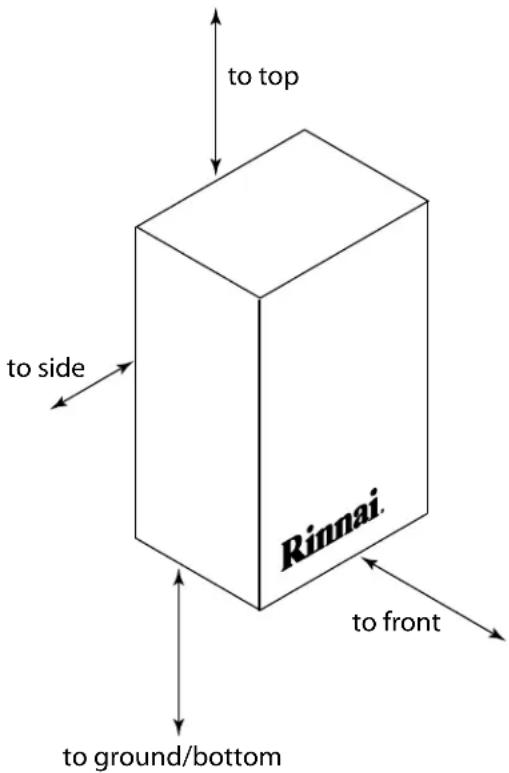
text_image
to top to side Rinnai. to front to ground/bottom* 4 inches (102 mm) for enclosed area; 1 inch (26 mm) for unenclosed area.
** 0 inches from vent components and condensate drain line.
The clearance for servicing is 24 inches in front of the water heater.
For closet installation: clearance is 6 inches (152 mm) from the front.
Attachment of the Water Heater
- Identify the installation location and confirm that the installation will meet all required clearances.
- Securely attach the water heater to the wall using any of the holes in the wall installation brackets which are at the top and bottom of the water heater. Ensure that the attachment strength is sufficient to support the weight. Refer to the weight of the water heater in the Specifications section.
NOTE: Rinnai water heaters should be installed in an upright position. Do not install upside down or on its side.

text_image
wall installation bracketsThe water heater requires 120 VAC, 60 Hz power from a properly grounded circuit.
If using the 6 foot long power cord, plug it into a standard 3 prong 120 VAC, 60 Hz properly grounded wall outlet.
The wiring diagram is located on the Technical Sheet attached to the inside of the front cover.
The water heater must be electrically grounded in accordance with local codes, or in the absence of local codes with the National Electrical Code, ANSI/NFPA 70 and/or the CSA C22.1, Canadian Electrical Code.
Error Indication or Air Handler Control Switch (RL75i, and RL94i only)
When using the Rinnai water heater with an Error Indication Switch, switch No. 4 in the bank of 8 switches should be in the off position. This is the default position.
To connect the water heater to the Rinnai Air Handler, the Control Switch is necessary to function as the electrical connection. When the Control Switch is functioning as the electrical connection between the water heater and air handler, switch No. 4 in the bank of 8 switches should be in the on position.
The Error Indication Switch and the Rinnai Air Handler Control Switch are optional products available from Rinnai. Installation instructions are included with these products.
G a s P i p i n g
General Instructions
- A manual gas control valve must be placed in the gas supply line to the Rinnai water heater. A union can be used on the connection above the shut off valve for the future servicing or disconnection of the unit.
- Check the type of gas and the gas inlet pressure before connecting the Rinnai water heater. If the Rinnai water heater is not of the gas type that the building is supplied with, DO NOT connect the water heater. Contact the dealer for the proper unit to match the gas type.
- Check the gas supply pressure immediately upstream at a location provided by the gas company. Supplied gas pressure must be within the limits shown in the Specifications section.
- Before placing the appliance in operation all joints including the heater must be checked for gas tightness by means of leak detector solution, soap and water, or an equivalent nonflammable solution, as applicable. (Since some leak test solutions,
including soap and water, may cause corrosion or stress cracking, the piping shall be rinsed with water after testing, unless it has been determined that the leak test solution is non-corrosive.)
- Always use approved connectors to connect the unit to the gas line. Always purge the gas line of any debris before connection to the water heater.
- The gas supply line shall be gas tight, sized, and so installed as to provide a supply of gas sufficient to meet the maximum demand of the heater and all other gas consuming appliances at the location without loss of pressure.
- Any compound used on the threaded joint of the gas piping shall be a type which resists the action of liquefied petroleum gas (propane / LPG).
- Refer to an approved pipe sizing chart if in doubt about the size of the gas line.
Pipe Sizing Procedure - Example
The gas supply must be capable of handling the entire gas load at the location. Gas line sizing is based on gas type, the pressure drop in the system, the gas pressure supplied, and gas line type. For gas pipe sizing in the United States, refer to the National Fuel Gas Code, NFPA 54. For Canadian gas pipe sizing, refer to the Natural Gas and Propane Installation Code CAN/CSA B149.1. The below information is provided as an example. The appropriate table from the applicable code must be used.
- For some tables, you will need to determine the cubic feet per hour of gas required by dividing the gas input by the heating value of the gas (available from the local gas company). The gas input needs to include all gas products at the location and the maximum BTU usage at full load when all gas products are in use.
$$ \text { Cubic Feet per Hour (CFH) } = \frac {\text { Gas Input of all gas products }}{\text { Heating Value of Gas } ^ {3}) (\text { BTU / FT })} \quad \text {(BTU / HR)} $$
- Use the table for your gas type and pipe type to find the pipe size required. The pipe size must be able to provide the required cubic feet per hour of gas or the required BTU/hour.
Example: The heating value of natural gas for your location is 1000 BTU/FT ^3 . The gas input of the RL94i is 199,000 BTU/HR. Additional appliances at the location require 65,000 BTU/hr. Therefore the cubic feet per hour = (199,000 + 65,000) / 1000 = 264 FT ^3 /HR. If the pipe length is 10 feet then the 3/4 inch pipe size is capable of supplying 264 FT ^3 /HR of natural gas.
Pipe Sizing Table - Natural Gas
Schedule 40 Metallic Pipe
| Inlet Pressure: | less than 2 psi (55 inches W.C.) |
| Pressure Drop: | 0.3 inches W.C. |
| Specific Gravity: | 0.60 |
Capacity in cubic feet per hour
| Length | Pipe Size (inches) | |||
| 3/4 1 | 1 1/4 1 1/2 | |||
| 10 | 273 | 514 | 1060 | 1580 |
| 20 | 188 | 353 | 726 | 1090 |
| 30 | 151 | 284 | 583 | 873 |
| 40 | 129 | 243 | 499 | 747 |
| 50 | 114 | 215 | 442 | 662 |
| 60 | 104 | 195 | 400 | 600 |
| 70 | 95 | 179 | 368 | 552 |
| 80 | 89 | 167 | 343 | 514 |
| 90 | 83 | 157 | 322 | 482 |
| 100 | 79 | 148 | 304 | 455 |
| 125 | 70 | 131 | 269 | 403 |
| 150 | 63 | 119 | 244 | 366 |
| 175 | 58 | 109 | 224 | 336 |
| 200 | 54 | 102 | 209 | 313 |
Pipe Sizing Table - Propane Gas
Schedule 40 Metallic Pipe
| Inlet Pressure: | 11.0 inches W.C. |
| Pressure Drop: | 0.5 inches W.C. |
| Specific Gravity: | 1.50 |
| Capacity in Thousands of BTU per Hour | |
| Length | Pipe Size (inches) | |||
| 1/2 | 3/4 | 1 1 | ||
| 10 | 291 | 608 | 1150 | 2350 |
| 20 | 200 | 418 | 787 | 1620 |
| 30 | 160 | 336 | 632 | 1300 |
| 40 | 137 | 287 | 541 | 1110 |
| 50 | 122 | 255 | 480 | 985 |
| 60 | 110 | 231 | 434 | 892 |
| 80 | 101 | 212 | 400 | 821 |
| 100 | 94 | 197 | 372 | 763 |
| 125 | 89 | 185 | 349 | 716 |
| 150 | 84 | 175 | 330 | 677 |
| 175 | 74 | 155 | 292 | 600 |
| 200 | 67 | 140 | 265 | 543 |
Isolation Valves and Pressure Relief Valve (RL75i and RL94i)
The isolation valves provide the ability to isolate the water heater from the structure's plumbing and allow quick access to flush the heat exchanger. Check with local codes to determine if a pressure and temperature relief valve is required. The included valves meet American National Standard (ANSI Z21.10.3) / Canadian Standard (CSA 4.3) and are ANSI/NSF 61 approved for potable water.
| Isolation Valve (Cold) | 107000081 |
| Isolation Valve (Hot) | 107000083 |
| Pressure Relief Valve (PRV) | 107000085 |
Isolation Valves Installation Instructions:
- Wrap the ends of the threaded water inlet & outlet on the tankless water heater, as well as the threaded end of the approved pressure relief valve with a minimum of 5 wraps of Teflon® tape.
- Screw the pressure relief valve into the 3/4" threads opposite the wing handle on the HOT water service valve. (RED drain handle) (see Pressure Relief Valve Section for proper installation requirements)
- Loosen the 3/4" union nut on the HOT water valve and connect to the HOT water outlet on the tankless water heater. If nut is removed, ensure that you realign the tailpiece accurately to the valve and that the black washer is positioned such that the raised metal edge of the valve is inside the washer.
- Align the direction of the HOT water drain to the desired position.
- Tighten the union assembly to the HOT water valve using approximately 15 foot lbs of torque.
- Repeat steps 3-5 for the COLD water valve. (BLUE drain handle) for connection to the COLD water inlet on the tankless water heater.
- Connect the INLET on the COLD water valve to the MAIN SOURCE of the water supply.
- Connect the OUTLET on the HOT water valve to the HOT WATER plumbing system.
- Ensure that both drain valve lever handles are in the closed position (perpendicular to the drain portion of the body).

Pressure Relief Valve Installation Instructions:
The PRV must be connected by the threaded connection opposite the wing handle on the hot water valve (designated by the RED drain handle) or the threaded connection on the side of the relocation fitting above the hot water valve. Installation must maintain a 34 " port size with no shut off valve or line restriction in-between the appliance and the PRV. The discharge line from the PRV should pitch downward and terminate 6" above drains where discharge will be clearly visible. The discharge end of the line shall be plain (unthreaded) and a minimum of 34 " in diameter. The discharge line material must be suitable for water at least 180° Fahrenheit and can be no more than 30 feet in length and contain no more than 4 elbows or bends. No valve of any type may be installed in the discharge line of the pressure relief valve.
Pressure Relief Valve Maintenance:
For proper care of this approved pressure relief valve, it is recommended that the valve is manually operated once a year. In doing so, it will be necessary to take precautions with regard to the discharge of potentially scalding hot water under pressure. Ensure discharge has a place to flow. Contact with your body or other property may cause damage or harm. Please note that only the PRV in this package is certified by CSA International as an approved item.
Piping Requirements
- A manual water control valve must be placed in the water inlet connection to the Rinnai water heater before it is connected to the water line. Unions may be used on both the hot and cold water lines for future servicing and disconnection of the unit.
- The piping (including soldering materials) and components connected to this appliance must be approved for use in potable water systems.
-
Purge the water line to remove all debris and air. Debris will damage the Rinnai water heater.
-
Toxic chemicals such as those used for boiler water treatment are not to be introduced to the potable water used for space heating.
- If the appliance will be used as a potable water source, it must not be connected to a system that was previously used with a nonpotable water heating appliance.
- Ensure that the water filter on the Rinnai water heater is clean and installed.
Pressure Relief Valve Requirements
- An approved pressure relief valve is required by the American National Standard (ANSI Z21.10.3) / Canadian Standard (CSA 4.3) for all water heating systems, and shall be accessible for servicing.
- The relief valve must comply with the standard for Relief Valves and Automatic Gas Shutoff Devices for Hot Water Supply Systems ANSI Z21.22 and /or the standard Temperature, Pressure, Temperature and Pressure Relief Valves and Vacuum Relief Valves, CAN1-4.4.
- The relief valve must be rated up to 150 psi and to at least the maximum BTU/hr of the appliance.
- The discharge from the pressure relief valve should be piped to the ground or into a drain system to prevent exposure or possible burn hazards to humans or other plant or animal life. Follow local codes. Water discharged from the relief valve could cause severe burns instantly, scalds, or death.
-
The pressure relief valve must be manually operated once a year to check for correct operation.
-
The relief valve should be added to the hot water outlet line and near the hot water outlet according to the manufacturer's instructions. DO NOT place any other type valve or shut off device between the relief valve and the water heater.
- Do not plug the relief valve and do not install any reducing fittings or other restrictions in the relief line. The relief line should allow for complete drainage of the valve and the line.
- If a relief valve discharges periodically, this may be due to thermal expansion in a closed water supply system. Contact the water supplier or local plumbing inspector on how to correct this situation. Do not plug the relief valve.
- Neither Rinnai nor the American National Standard (ANSI Z21.10.3) / Canadian Standard (CSA 4.3) requires a combination temperature and pressure relief valve for this appliance. However, local codes may require a combination temperature and pressure relief valve.
Freeze Protection
The freeze protection features include electrical heating elements. Freeze protection may be disabled if electricity is not supplied, or if there is an error preventing the water heater from functioning. Loss of freeze protection may result in water damage from a burst heat exchanger or water lines.
The installation of auto drain down solenoid valves is optional. However, Rinnai strongly recommends that these valves be installed to prevent damage from freezing in case the normal freeze protection should become disabled. Any product damage due to freezing will not be covered by the warranty.
In addition, the solenoid valves should be connected electrically to a surge protector with terminals. This allows the solenoid valves to operate if the water heater is disabled due to an error code.
The solenoid valves and surge protector with terminals are available for purchase at Rinnai.
The freeze protection features will not prevent the external piping from freezing. Rinnai recommends heat tracing and insulating hot and cold water pipes connecting units. Pipe cover enclosures may be packed with insulation for added freeze protection.
With electrical power supplied, Rinnai water heaters will not freeze when the outside air temperature is as cold as -22^ (-30°C) for indoor models or is as cold as -4^ (-20°C) for outdoor models, when protected from direct wind exposure. Because of the “wind-chill” effect, any wind or circulation of the air on the unit will reduce its ability to freeze protect.
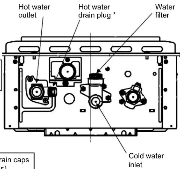
Manual draining of the water heater

WARNING
To avoid burns, wait until the equipment cools down before draining the water. The water in the appliance will remain hot after it is turned off.
If the water heater is not going to be used during a period of possible freezing weather, it is recommended that the water inside the water heater be drained.
To manually drain the water:
- Shut off cold water supply and gas supply.
- Turn off the temperature controller.
- Disconnect the power to the water heater.
- Open hot water drain plug at the hot water outlet.
- Remove water filter to drain the cold water.
If an isolation kit is installed, remove the drain caps on both isolation valves and open both valves above the caps (blue and red valve handles).
To resume normal operation:
- Confirm that all water drain plugs are removed, that the gas supply is turned off, and that all taps are closed.
- Screw in the hot water drain plug.
- Screw in the water filter in the cold water inlet.
If the isolation kit was used to drain the unit, replace the drain caps and close both isolation valves (blue and red valve handles).
- Open the cold water supply.
- Open a tap and confirm that water flows, and then close.
- Turn on the power.
- After confirming that the temperature controller is off, turn on the gas supply.
- Turn on the temperature controller.
text_image
Hot water outlet Hot water drain plug * Water filter Cold water inlet rain caps s)* Use a wrench or other tool to unscrew the hot water drain plug.
Running a low volume of water through the water heater to prevent freezing
If the temperature exceeds the ability of the water heater to freeze protect itself, or if power is lost, the following steps may prevent the water heater and external piping from freezing. (Units connected with MSA or EZConnect should be drained to prevent freezing if not in use.)
- Turn the water heater off.
- Close the gas supply valve.
- Reduce the flow to about 0.1 gal/min or to where the stream is about 0.2 inches thick.

natural_image
Diagram of a laboratory apparatus with a curved tube and flasks, showing a blue measurement arrow (no text or labels)0.1 gal/min or about 0.2 inch thick
When the water heater or external piping has frozen
- Do not operate the water heater if it or the external piping is frozen.
- Close the gas and water valves and turn off the power.
- Wait until the water thaws. Check by opening the water supply valve.
- Check the water heater and the piping for leaks.
22 VB Series Indoor LS Manual
NOTICE
Warranty does not cover damage due to freezing.
In the event of a power failure at temperatures below freezing the water heater should be drained of all water to prevent freezing damage.
The unit may be drained manually. However, Rinnai highly recommends that drain down solenoid valves be installed that will automatically drain the unit if power is lost. Rinnai also recommends the installation of a surge protector with terminals which allows the solenoid valves to operate if the unit is disabled due to an error code.
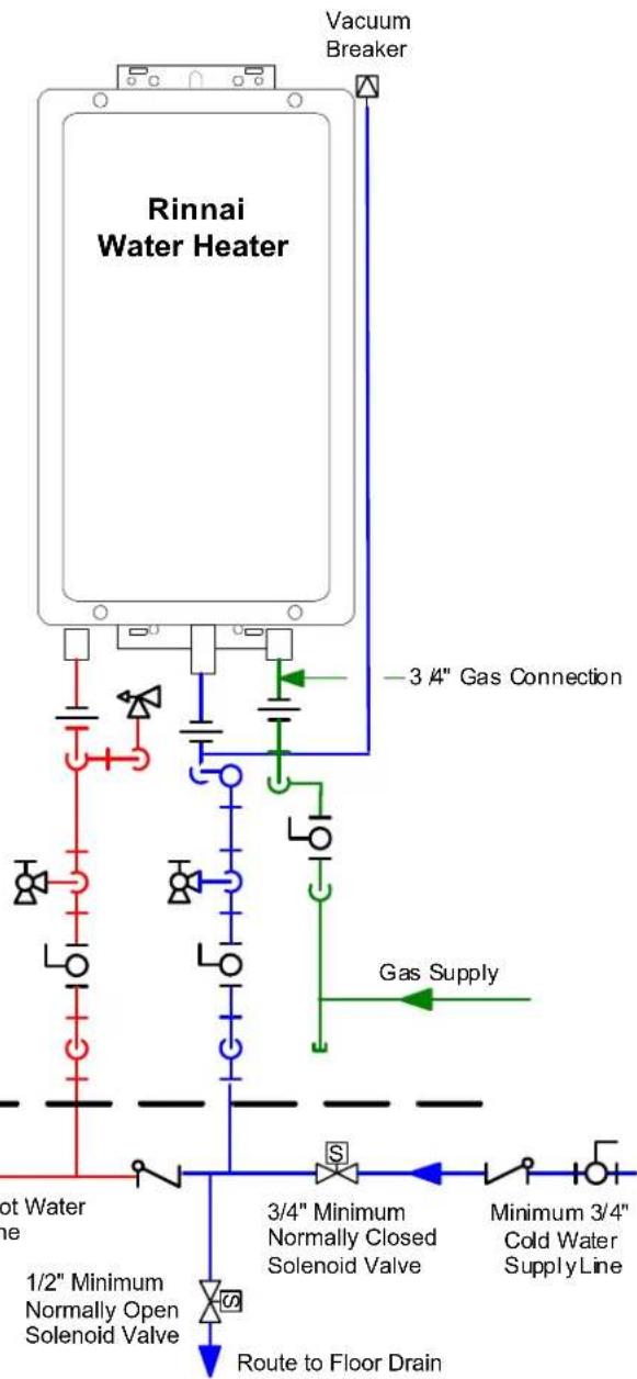
When the electrical power to the water heater fails, the 3/4" solenoid valve closes (stopping the flow of water into the heater) and the 1/2" solenoid valve opens (allowing the water heater and associated piping to drain. Ensure that you run the drain for the solenoids to the outside environment to prevent discharging water inside the building causing water damage).
NOTE:
Heat trace ALL water pipe and fittings located outside home (attic, crawl space) or building structure. (ALL water pipe and fittings shown above the dashed line in the drawing.)
NOTE:
ALL pipe and fittings shown below dashed line should be located inside home or building structure.
The vacuum breaker line should be located inside the building structure.
flowchart
graph TD
    A["Rinnai Water Heater"] --> B["Gas Supply"]
    B --> C["3/4" Gas Connection"]
    C --> D["Minimum 3/4" Cold Water Supply Line"]
    D --> E["3/4" Minimum Normally Closed Solenoid Valve"]
    E --> F["Route to Floor Drain"]
    F --> G["1/2" Minimum Normally Open Solenoid Valve"]
    G --> H["Not Water Line"]
    H --> I["Vacuum Breaker"]
    style A fill:#f9f,stroke:#333
    style B fill:#ccf,stroke:#333
    style C fill:#cfc,stroke:#333
    style D fill:#fcc,stroke:#333
    style E fill:#cff,stroke:#333
    style F fill:#ffc,stroke:#333
    style G fill:#cfc,stroke:#333
    style H fill:#fcc,stroke:#333
    style I fill:#ffc,stroke:#333
KEY
| [3HZ] | 3/4" Ball Valve | [03ZW] | Pressure Regulator |
 | 3/4" Union |  | Circulating Pump |
 | Check Valve |  | Boiler Drain Valve |
 | Pressure Relief Valve |  | Solenoid Valve |

text_image
Rinnai Water Heater 3/4" Hot Water Supply Line For Building Fixtures Gas Supply 3/4" Cold Water Supply Line 3/4" Gas Connection Rinnai Equipment List QTY Rinnai Water Heaters 1 RIK-KIT (Optional) 1 (3/4" Fittings Include: 2 Unions, 2 Ball Valves, 2 Drain Valves and 1 Pressure Relief Valve.)| KEY | This is not an engineered drawing. It is intended only as a guide and not as a replacement for professionally engineered project drawings. This drawing is not intended to describe a complete system. It is up to the contractor/engineer to determine the necessary components and configuration of the particular system being installed. This drawing does not imply compliance with local building code requirements. It is the responsibility of the contractor/engineer to ensure installation is in accordance with all local building codes. Confer with local building officials before installation. | |||
| [D54S] | 3/4" Ball Valve |  | Pressure Regulator | |
| 3/4" Union | Circulating Pump | |||
 | Check Valve |  | Boiler Drain Valve | |
| Pressure Relief Valve | Solenoid Valve | |||
NOTE:
For residential and commercial applications, this piping arrangement maintains full warranty.
For this application:
Pump should be controlled by an Aquastat, Timer or Combination Aquastat and Timer.
Pump to be sized to maintain circulation loop temperature.
The pump should be sized to overcome the pressure loss through the tank water heater, and supply and return plumbing. Reference the Rinnai Hot Water System Design Manual, Pump Sizing for Circulation.
Pump to be of bronze or stainless construction.
IMPORTANT: Connect the building return line to the hot water supply line as close as possible to the Rinnai Water Heater.

flowchart
graph TD
    A["Rinnai Water Heater"] --> B["3/4" Gas Connection"]
    A --> C["Gas Supply"]
    A --> D["Tank Water Heater to be Sized for Heat Loss of Circulation Loop."]
    A --> E["Electric Water Heater"]
    E --> F["Building Supply"]
    F --> G["Expansion Tank"]
    H["Rinnai Equipment List"] --> I["QTY"]
    J["Rinnai Water Heaters"] --> K["1"]
    L["RIK-KIT (Optional) (3/4" Fittings Include: 2 Unions, 2 Ball Valves, 2 Drain Valves and 1 Pressure Relief Valve.)"] --> M["1"]
    N["Minimum 3/4" Cold Water Supply Line"] --> O["Blue Box"]
    P["Building Fixtures"] --> Q["Red Down Arrow"]
    R["Green Box"] --> S["Blue Box"]
    T["Red Down Arrow"] --> U["Blue Box"]
| KEY | This is not an engineered drawing. It is intended only as a guide and not as a replacement for professionally engineered project drawings. This drawing is not intended to describe a complete system. It is up to the contractor/engineer to determine the necessary components and configuration of the particular system being installed. This drawing does not imply compliance with local building code requirements. It is the responsibility of the contractor/engineer to ensure installation is in accordance with all local building codes. Confer with local building officials before installation. | |||
| [30K6] | 3/4" Ball Valve |  | Pressure Regulator | |
| 3/4" Union |  | Circulating Pump | ||
| Check Valve |  | Boiler Drain Valve | ||
| [542A] | Pressure Relief Valve |  | Solenoid Valve | |
Intake / Exhaust Guidelines
Refer to the specific instructions on your vent product for additional installation requirements.
- This water heater is a direct vent water heater and therefore is certified and listed with the vent system. You must use vent components that are certified and listed with the water heater model.
- Do not combine vent components from different manufacturers.
- The vent system must vent directly to the outside of the building and use outside air for combustion.
- Venting should be as direct as possible with a minimum number of pipe fittings.
- Avoid dips or sags in horizontal vent runs by installing supports per the vent manufacturer's instructions.
- Support horizontal vent runs every four feet and all vertical vent runs every six feet or in accordance with local codes.
- Vent diameter must not be reduced.
-
Do not connect the venting system with an existing vent or chimney.
-
Do not common vent with the vent pipe of any other water heater or appliance.
- Vent connections must be firmly pressed together so that the gaskets form an air tight seal.
- RL75i, RL94i: The vent piece connected to the water heater must be secured with one self-tapping screw.
- Refer to the instructions of the vent system manufacturer for component assembly instructions.
- If the vent system is to be enclosed, it is suggested that the design of the enclosure shall permit inspection of the vent system. The design of such enclosure shall be deemed acceptable by the installer or the local inspector.
NOTICE
If it becomes necessary to access an enclosed vent system for service or repairs, Rinnai is not responsible for any costs or difficulties in accessing the vent system. Warranty does not cover obtaining access to an enclosed vent system.
Condensate
Condensate formation can occur in high efficiency direct vent appliances. To prevent condensate damage follow these instructions.
- Vertical terminations must incorporate a condensate drain and trap as close as possible to the appliance.
- RL75i, and RL94i water heaters have an integrated condensate collector.
• Rinnai offers a condensate trap. - Regions of cold climate will create more condensate in the vent system. The condensate collector should be used in cold climates.
- Use only vent that is approved and identified as acceptable for your particular model.
- Do not use PVC, CPVC, ABS or galvanized material to vent this appliance.
- Slope the venting toward the appliance according to the vent manufacturers installation instructions.
- All condensate must drain and be disposed of per local codes.
- Use only PVC or CPVC pipe for the condensate drain line.
- The condensate drain pipe should be as short as possible and have a downward pitch.
- Do not connect the condensate drain pipe directly to the rain sewer.
WARNING
The condensate trap must be primed before operation to prevent exhaust gases from entering the building.
NOTICE
Provisions must be made to prevent the condensate from entering the water heater. Without proper drainage or disposal, condensate will damage the heat exchanger.
Do not plug or cap the integrated condensate line. Without proper drainage or disposal, condensate will damage the water heater.
- The condensate drain pipe (along its entire length) must be at least the same diameter as the drain line, (3/8 inch NPT).
- The end of the condensate drain pipe should be open to the atmosphere. The end should not be under water or other substances.
- Do not connect the condensate drain line with an air conditioning evaporator coil drain.
- To minimize freezing of the condensate, run the condensate drain line through an interior wall or between insulation and an interior wall.
- The condensate collector should be used for all hydronic heating applications.
Maximum Vent Length
- Determine the number of 90 degree elbows in the vent system. (Two 45 degree elbows count as one 90 degree elbow. On the R98 models each one foot of semi rigid flex duct used in the air intake length is equivalent to one 90 degree elbow.)
- Refer to the table to find the maximum vent length based on the number of elbows.
- Follow the applicable note.
Example: If you have one elbow then your maximum vent length is 35 feet (10.7 m). If your actual length is greater than 15 ft (4.6 m) then move switch no. 1 (SW1) to OFF.
| Number of 90° Elbows | ||||||
| 0 1 2 | 3 4 5 6 | |||||
| 41 ft 1(12.5 m) | 35 ft 2(10.7 m) | 29 ft 3(8.8 m) | 23 ft 4(7.0 m) | 17 ft 4(5.2 m) | 11 ft 4(3.4 m) | 5 ft 4(1.5 m) |
① If the length is greater than 21 ft (6.4 m) then move switch no. 1 (SW1) to OFF.
② If the length is greater than 15 ft (4.6 m) then move switch no. 1 (SW1) to OFF.
③ If the length is greater than 9 ft (2.7 m) then move switch no. 1 (SW1) to OFF.
④ Move switch no. 1 (SW1) to OFF.

text_image
Notes ①②③④ → Switch No. ON O F F 1 2 3 4 5 6 7 8NOTICE
If you have a longer vent length, switch no. 1 is required to be in the OFF position. This ensures the water heater will run properly. Blocked flue error codes and shutdowns may result if switch no. 1 is not in the correct position. On the RL94i, the maximum water flow capacity will be reduced by about 10% when switch no. 1 is OFF.
Vent Products
Listed and Tested Vent Products for
RL75i....REU-VB2528FFUD-US
RL94i....REU-VB2735FFUD-US
| Manufacturer | Product | Parts |
| Rinnai/Ubbink Rolux | Vent System | Refer to the manufacturer's technical literature for specific part numbers and instructions. |
| Heat-Fab Saf-T Vent | SC system | |
| Metal-Fab | Corr/Guard Vent/Air Intake System |
Listed and Tested Vent Products for
R98LSi.... REU-VA3237FFU
R98LSi-ASME ..... REU-VA3237FFU-ASME
| Manufacturer | Product | Appliance Adapter | Vertical Termination | Horizontal Termination | Horizontal Concentric Termination | Adjustable Horizontal Concentric Termination |
| Heat-Fab Saf-T Vent 94 | 01AMTK 5400 | CI 9492 NA | NA | |||
| Z-Flex Z-Vent 2SVSNA | A04.5 2SVSRO | F4 2SVSTPX4 NA | NA | |||
| ProTech Systems | FasNSeal | FSAAU4 * | FSRC4 * | FSBS4 * | FSDVPTB04LH * FSDVWT4 | FSDVWMTP4LH, FSEDVWMTP4LH |
| Metal-Fab | Corr/Guard | 4CGOA | 4CGSWC | 4CGSWMCM | 4CG7HT90 4CG7HT | NA |
* When ordering from Rinnai, ask for these part numbers or kits:
FSAAU4 - ask for FSAAU4SP (single pack)
FSRC4 - ask for FSVPK4 Variable Pitch Roof Flashing Kit (includes rain cap FSRC4, storm collar, roof jack, and roof flashing)
FSBS4 - ask for FSBS4SP (single pack)
FSDVPTB04LH - ask for FSDVWMT04LH Kit (includes direct vent pass through FSDVPTB04LH, bird screen, exterior and interior mounting plates, appliance adapter, 3 foot flexible aluminum duct with 2 clamps, and adjustable vertical length)
Vent Manufacturer Contact Information for Installation Instructions and Parts Lists:
Rinnai/Ubbink
Heat-Fab
Z-Flex
Telephone: 800-621-9419
Telephone: 800-772-0739
Telephone: 800-654-5600
Fax: 678-829-1666
Fax: 413-863-4803
Fax: 888-889-3539
Web Site: www.rinnai.us
E-mail: custsvc@heat-fab.com
E-mail: sales@z-flex.com
Web Site: www.heatfab.com
Web Site: www.novaflex.com
ProTech Systems, Inc.
Metal-Fab Inc.
Telephone: 800-766-3473
Telephone: 800-835-2830
518-463-7284
316-943-2351
Fax: 518-463-5271
Fax: 316-943-2717
E-mail: support@protechinfo.com
E-mail: info@mtlfab.com
Web Site: www.protechinfo.com
Web Site: www.metal-fabinc.com
text_image
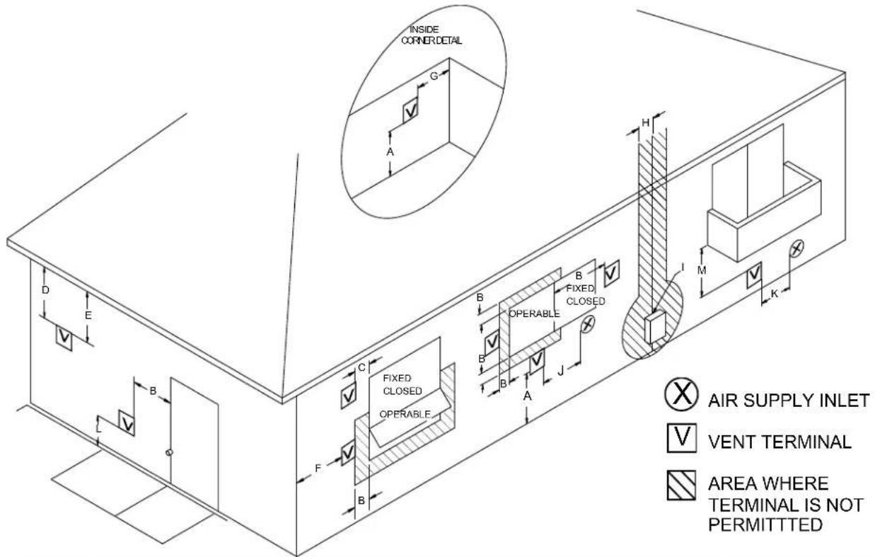
INSIDE CORNER DETAIL G A H D E C FIXED CLOSED OPERABLE B F B B A J B FIXED CLOSED OPERABLE B I M K AIR SUPPLY INLET VENT TERMINAL AREA WHERE TERMINAL IS NOT PERMITTED| Ref | Description Canadian Installations US Installations | ||
| A | Clearance above grade, veranda, porch, deck, or balcony | 12 inches (30 cm) | 12 inches (30 cm) |
| B | Clearance to window or door that may be opened | 36 inches (91 cm) | 12 inches (30 cm) |
| C Clearance to permanently closed window | * | * | |
| D | Vertical clearance to ventilated soffit, located above the terminal within a horizontal distance of 2 feet (61 cm) from the center line of the terminal | * | * |
| E Clearance to unventilated soffit | * | * | |
| F Clearance to outside corner | * | * | |
| G | Clearance to inside corner | * | * |
| H | Clearance to each side of center line extended above meter/regulator assembly | 3 feet (91 cm) within a height 15 feet (4.5 m) above the meter/regulator assembly | * |
| I | Clearance to service regulator vent outlet | 36 inches (91 cm) | * |
| J | Clearance to nonmechanical air supply inlet to building or the combustion air inlet to any other appliance | 36 inches (91 cm) 12 inches (30 cm) | |
| K Clearance to a mechanical air supply inlet | 6 feet (1.83 m) | 3 feet (91 cm) above if within 10 feet (3 m) horizontally | |
| L | Clearance above paved sidewalk or paved driveway located on public property | 7 feet (2.13 m) 1 | * |
| M | Clearance under veranda, porch, deck, or balcony | 12 inches (30 cm) 2 | * |
① A vent shall not terminate directly above a sidewalk or paved driveway that is located between two single family dwellings and serves both dwellings.
② Permitted only if veranda, porch, deck, or balcony is fully open on a minimum of two sides beneath the floor.
* For clearances not specified in ANSI Z223.1/NFPA 54 or CSA B149.1, clearances are in accordance with local installation codes and the requirements of the gas supplier.
Clearance to opposite wall is 24 inches (60 cm) for Canada and US.
Local codes supersede these clearances.
- Avoid termination locations near a dryer vent.
- Avoid termination locations near commercial cooking exhaust.
- For VA3237 air intake position, follow the ANS Z21.10.3 • CSA 4.3 requirements on the previous page.

Vent terminal (represents concentric vent terminal or VA3237 exhaust only vent terminal)

text_image
(0.91 m) to ventilated or unventilated soffit or eve vent; or to a deck or porch 36" 12" (0.30 m) to an inside corner V V 12" (0.30 m) between Rinnai terminals at same level INSIDE CORNER
(1.52 m) vertically between Rinnai terminals
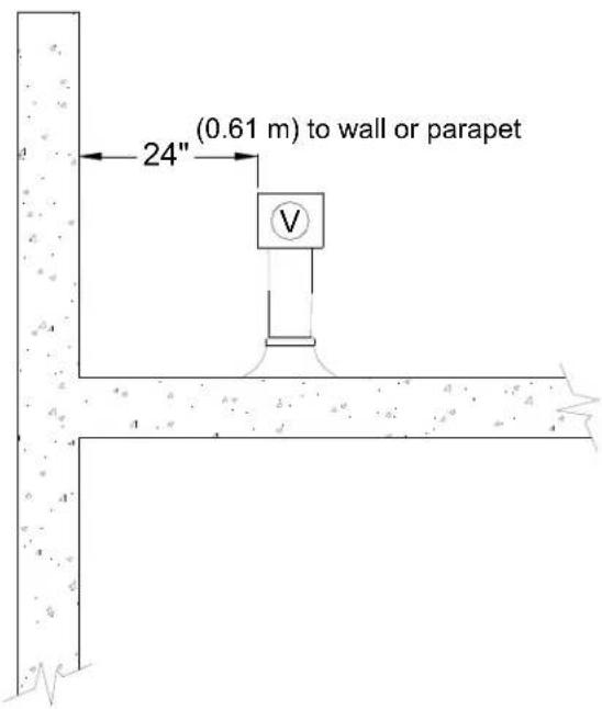
text_image
(0.61 m) to wall or parapet 24"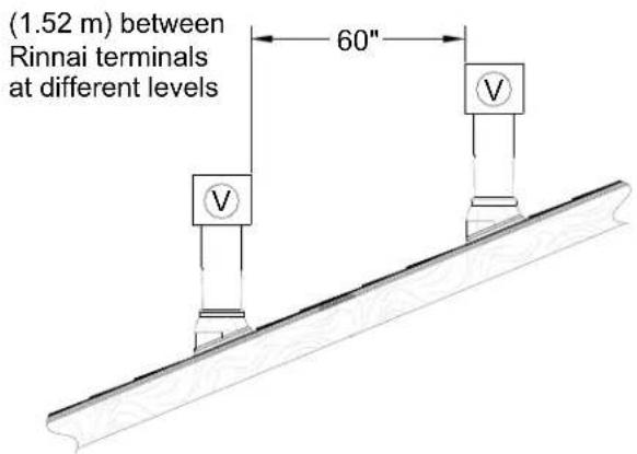
text_image
(1.52 m) between Rinnai terminals at different levels 60"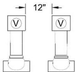
text_image
12"(0.30 m) between Rinnai terminals at same level
Horizontal Termination without using the Condensate Collector

WARNING
If the condensate collector is not used, the drain pipe must be capped to prevent exhaust gases and condensate from entering the building. The cap is supplied on the appliance.

natural_image
Technical line drawing of a mechanical assembly with pipe connection and rotation arrow (no text or symbols)* The condensate collector must be used in horizontal terminations if a vertical rise in the vent system exceeds 5ft.

text_image
Maximum Height * 5 feet (1.52 m)
text_image
sector must be used ons if a vertical rise needs 5ft.Regions of cold climate will create more condensate in the vent system. The condensate collector should be used in cold climates.
If more than one elbow is used in the vertical section the condensate collector must be used.
Horizontal Termination using the Condensate Collector
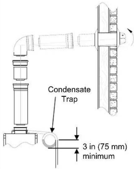
text_image
Condensate Trap 3 in (75 mm) minimumVertical Termination
(condensate collector must be used in all installations)

text_image
3 in (75 mm) minimum 3 in (75 mm) minimum
text_image
Condensate Collector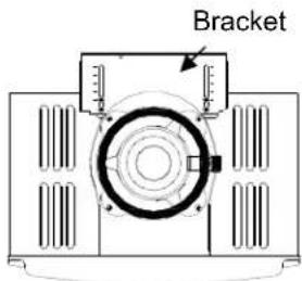
text_image
BracketTo adjust the condensate collector position or to replace the female vent top with a male vent top:
- Loosen the 4 screws at the rear bracket
- Slide the bracket away from the female vent top.
- Remove the 4 screws attaching the female vent top to the water heater.
- Lift up the female vent top and reposition as desired (or replace with a male vent top).
- Install the 4 screws at the vent top and tighten the 4 screws at the bracket.
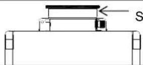
Securing Screw
Secure the first vent component to the water heater with one self-tapping screw at the hole located above the condensate collector.
Air Intake Assembly
The air intake system consists of a field supplied 4 inch diameter stainless steel, Schedule 40 PVC, ABS or CPVC pipe. A maximum 6 feet of semi-rigid flexible aluminum ducting can also be used. Foil wrapped dryer vent and cell core products are not authorized.
The air intake has a zero clearance to combustibles.
Air Intake Connection
- Drill 2 small holes at the end of the air intake pipe.
- Slide the pipe over the air intake terminal.
- Using a level, ensure the pipe is straight up and down.
- With self tapping screws, attach the pipe to the air intake terminal.
- Apply a bead of silicone around the pipe and air intake terminal, ensuring an air tight connection.
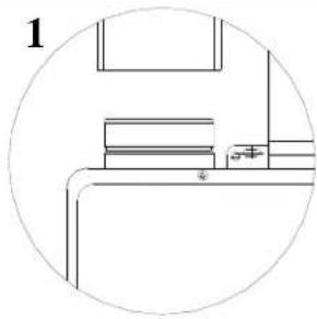
natural_image
Simple line drawing of a room interior with furniture and fixtures, no text or symbols present
natural_image
Pure architectural line drawing of a window frame structure without any text or symbols
natural_image
Technical line drawing of a mechanical assembly with no visible text or symbols
natural_image
Pure technical line drawing of a mechanical assembly without any text, numbers, or symbolsExhaust Pipe Assembly
Refer to the manufacturer's installation instructions for the specific exhaust vent system.
| Venting Clearances to Combustibles | ||
| Vent Size | Enclosed | Unenclosed |
| Horizontal & Horizontal & | ||
| 4" (102 mm) | 4" (102 mm) 1" (26 mm) | |
Horizontal Terminations
The air intake must be located in relation to the exhaust as shown below. The air intake must angle 1/4 inch per foot to the termination to prevent entry of rain.

text_image
6" Vent 8" Intake Optional IntakeThe vent termination and air intake must be in the same pressure zone and face the same direction.
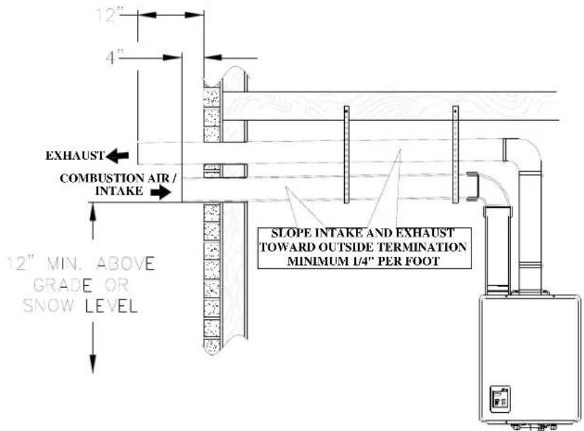
text_image
12" 4" EXHAUST COMBUSTION AIR/ INTAKE 12" MIN. ABOVE GRADE OR SNOW LEVEL SLOPE INTAKE AND EXHAUST TOWARD OUTSIDE TERMINATION MINIMUM 1/4" PER FOOTHorizontal with Concentric Termination
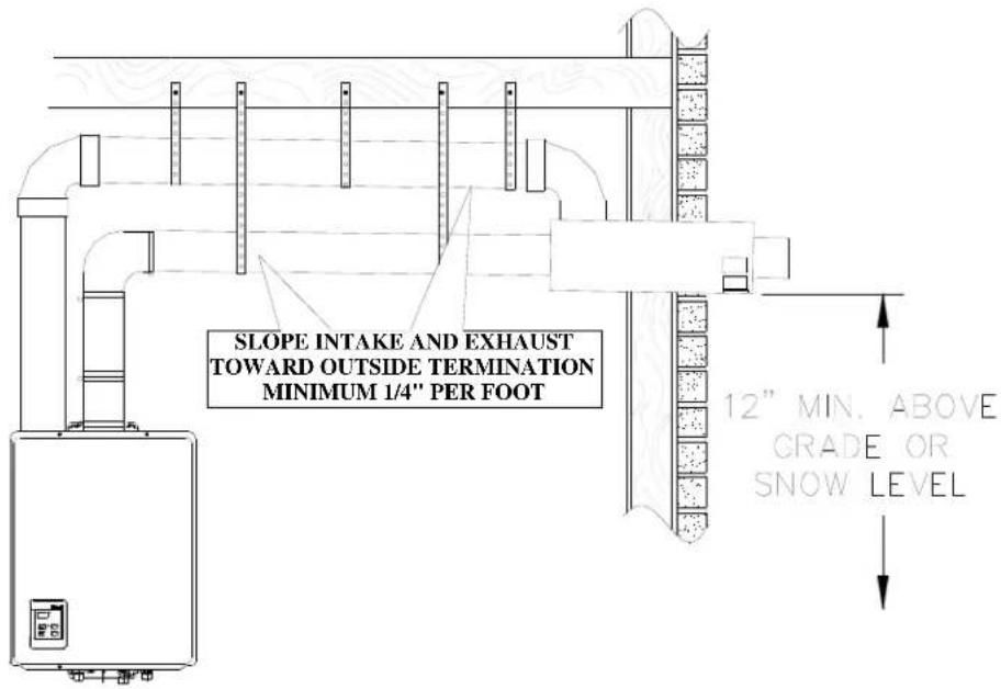
text_image
SLOPE INTAKE AND EXHAUST TOWARD OUTSIDE TERMINATION MINIMUM 1/4" PER FOOT 12" MIN. ABOVE GRADE OR SNOW LEVELVertical Terminations
The air intake requires a return bend or two 90° elbows to prevent entry of rain.
The vent termination and air intake must be in the same pressure zone.
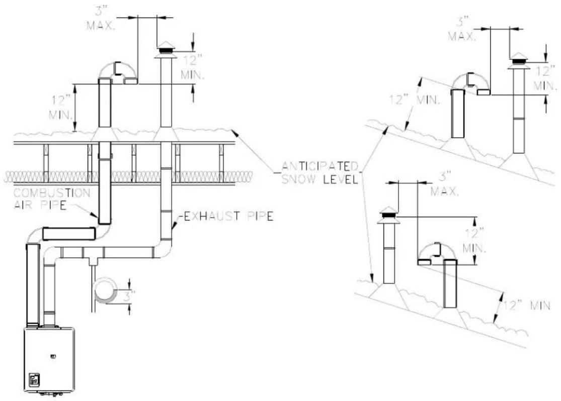
text_image
3" MAX. 12" MIN. 12" MIN. COMBUSTION AIR PIPE EXHAUST PIPE ANTICIPATED SNOW LEVEL 3" MAX. 12" MIN. 3" MIN.The EZConnect ^™ cable is an optional accessory that connects 2 water heaters and allows them to function as one hot water source.
The MSA-2M and MSA-2S packs are optional accessories that connect 2 to 5 water heaters and allow them to function as one hot water source.
Refer to the instructions that come with the accessory for complete installation information.
| Number of Connected Water Heaters: | Accessories Necessary: |
| 2 | (1) EZConnectTM Cable or (1) MSA-2M |
| 3 | (1) MSA-2M and (1) MSA-2S |
| 4 | (1) MSA-2M and (2) MSA-2S |
| 5 | (1) MSA-2M and (3) MSA-2S |
Guidelines
- Do not install both the EZConnect™ and the MSA packs because they are not designed to operate together.
- Water heaters connected with the EZConnect™ Cable or the MSA-2M and MSA-2S packs cannot be used for the bath fill function.
- Water heaters should be installed less than 18 inches apart so that the cables will reach between units and to prevent temperature fluctuations (cold water sandwich effect) when the water is shut off and turned back on.
- Temperature settings can only be changed on the controller for the primary unit. (This changes the temperature on all units within the MSA or EZConnect™ system.)
Activation Options for EZConnect™
One unit in standby allows for quicker activation time with flow rates within the capacity of a single unit.
Two units in standby allows for quicker delivery temperature for flow rates requiring both units.
Applicable for the RL75 and RL94 models only.
| Model | Number of units in standby | Position of switch No. 5 in bank of 6 switches |
| RL75, RL94 | 1 | ON |
| 2 | OFF (default) |
High Altitude Installations
Set switches 2 and 3 to the values shown in table below for your altitude. The default setting for the appliance is 0-2000 ft (0-610 m) with switches No. 2 and No. 3 in the OFF position.

WARNING
DO NOT adjust the other switches unless specifically instructed to do so.
| 0-2000 ft(0-610 m) | 2001-5200 ft(610-1585 m) | 5201-7700 ft(1585-2347 m) | 7701-10200 ft(2347-3109 m) | |
| Switch No. 2 OFF | OFF ON ON | |||
| Switch No. 3 OFF | ON OFF ON | |||
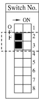 |  |  |  |
Water Heater High Altitude Installation Setting Procedure 610 - 1372 m (2001 - 4500 ft) for Canada Only / Procédure Reglage de Chaffeau á' Haute Altitude 610 - 1372 m (2001 - 4500 ft) pour Canada Seulement
DO NOT adjust the other switches unless specifically instructed to do so.

AVERTISSEMENT
Indoor models have their controller built into the front panel. A kit is available that allows the integrated controller to be removed and used as a remote controller. Additional controllers can also be installed.
Location
- The controller should be out of reach of small children.
- Avoid locations where the controller may become hot (near the oven or radiant heater).
-
Avoid locations in direct sunlight. The digital display may be difficult to read in direct sunlight.
-
Avoid locations where the temperature controller could be splashed with liquids.
- Do not install in locations where it can be adjusted by the public.
Configurations
A maximum of 4 temperature controllers, including wired and wireless, can be installed for a water heater or bank of water heaters. Controllers can only be wired in parallel. Controllers cannot be wired in series.
The 4 temperature controllers can consist of multiple MC-91's or MC-502RC's but only 1 BC-100V and only 1 MC-100V.
Any one of the 5 types of controllers can be installed by itself and still operate the water heater. All functions will be available with the exception that the clock function on the BC-100V will only be available if an MC-100V is also connected.
If 4 MC-91's are installed, simultaneously press the Priority and On/Off buttons on the fourth controller until a beep sounds.
The table to the right shows some of the possible combinations of controllers.

text_image
Rinnai Wire controllers in parallel Controllers| MC-91 | + | MC-91 | + | MCC-94 | MC-502RC |
| MC-91 | + | MCC-91 | + | MC-502RC | MC-502RC |
| MCC-91 | + | MC-502RC | + | BC-100V | + MC-100V |
| MC-91 | + | MC-502RC | + | BC-100V | + MC-100V |
| MC-91 | + | MC-91 | + | MC-502RC | BC-100V |
| MC-91 | + | MC-502RC | + | MC-502RG | MC-100V |
Cable Lengths and Size
The cable for the temperature controller should be a non-polarized two-core cable with a minimum gauge of 22 AWG. The maximum cable length from each controller to the water heater depends on the total number of wired controllers connected to the water heater.
| Number of Wired Controllers | Maximum Cable Length for each Controller to Water Heater |
| 1 | 328 ft (100 m) |
| 2 | 164 ft (50 m) |
| 3 or 4 | 65 ft (20 m) |
Mounting the Controller
Follow the procedure below to install MC-91 or MCC-91 temperature controllers.
- Determine a suitable location for the controller.
- Make three holes in the wall as shown.
- Run the cable between the controller and the Rinnai water heater or the controller and the other controller.
-
Remove the face plate from the temperature controller using a screwdriver.
-
Connect the cable to the temperature controller.
-
Mount the controller to the wall using the holes drilled in step 2.
-
Disconnect the power from the Rinnai water heater.
-
Remove the cover of the Rinnai water heater.
-
Remove the plastic cover from the PCB and electrical connections.
-
Thread the cable through the access hole at the base of the unit and connect the wires to the controller terminals on the right hand side bottom of the PCB.
-
Secure the controller cable using the clamp provided.
-
Replace plastic cover over PCB and then replace the cover of the Rinnai water heater.
WARNING
Do not attempt to connect the temperature controllers with the power on. There is 120 volt potential, next to the temperature controller connections inside the unit.
Do not connect the temperature controller to the 120VAC terminals provided for the optional solenoid drain valves.
All service and wiring should be performed by a registered installer.
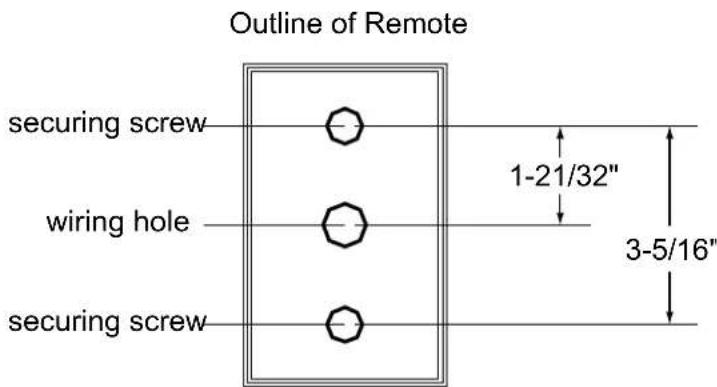
text_image
Outline of Remote securing screw wiring hole securing screw 1-21/32" 3-5/16"
text_image
TEMPERATURE CONTROLLER CONNECTION TERMINALS TEMPERATURE CONTROLLER CABLE CABLE CLAMPthese instructions exactly, a fire or explosion may result causing property damage, personal injury or loss of life.
A. This appliance does not have a pilot. It is equipped with an ignition device which automatically lights the burner. Do not try to light the burner by hand.
B. BEFORE OPERATING smell all around the appliance area for gas. Be sure to smell next to the floor because some gas is heavier than air and will settle on the floor.
WHAT TO DO IF YOU SMELL GAS
- Do not try to light any appliance.
- Do not touch any electric switch; do not use any phone in your building.
- Immediately call your gas supplier from a neighbor's phone. Follow the gas supplier's instructions.
- If you cannot reach your gas supplier, call the fire department.
C. Use only your hand to push in or turn the gas control knob. Never use tools. If the knob will not push in or turn by hand, do not try to repair it, call a qualified service technician. Force or attempted repair may result in a fire or explosion.
D. Do not use this appliance if any part has been under water. Immediately call a qualified service technician to inspect the appliance and to replace any part of the control system and any gas control which has been under water.
OPERATING INSTRUCTIONS
- STOP! Read the safety information above.
- Set the thermostat to lowest setting.
- Turn off all electric power to the appliance using the ON/OFF button.
- This appliance is equipped with an ignition device which automatically lights the burner. Do not try to light the burner by hand.
- Locate the manual gas valve on the side of the heater. Turn the manual valve clockwise to the full OFF position.
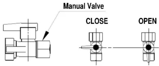
text_image
Manual Valve CLOSE OPEN- Wait five (5) minutes to clear out any gas. Then smell for gas, including near the floor. If you smell gas, STOP! Follow "B" in the safety information above. If you don't smell gas, go to the next step.
- Turn the manual gas valve counterclockwise to the full ON position.
- Turn on all electric power to the appliance using the ON/OFF button.
- Set the thermostat to desired setting.
- Open a hot water tap. If the appliance will not operate, follow the instructions "To Turn Off Gas To Appliance" and call your service technician or gas supplier. See manual for additional information.
TO TURN OFF GAS TO APPLIANCE
- Turn off all electric power to the appliance using the ON/OFF button.
-
Set the thermostat to lowest setting.
-
Locate the manual gas valve on the side of the heater. Turn the manual valve clockwise to the full OFF position.
Technical Data
Pressure Drop Curve
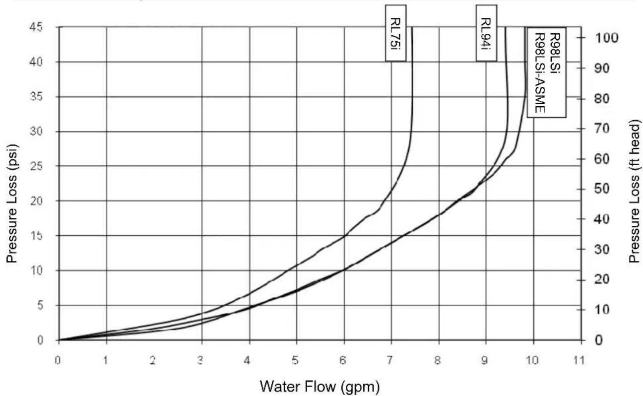
line
| Water Flow (gpm) | Pressure Loss (psi) | | ---------------- | ------------------- | | 0 | 0 | | 1 | ~1 | | 2 | ~3 | | 3 | ~5 | | 4 | ~8 | | 5 | ~12 | | 6 | ~18 | | 7 | ~25 | | 8 | ~35 | | 9 | ~50 | | 10 | ~70 | | 11 | ~90 |Outlet Flow Data

line
| delta T - Temperature Rise (°F) | RL94i | RL75i | R98LSi | R98LSi-ASME | | ------------------------------- | ----- | ----- | ------ | ----------- | | 0 | 0.0 | 0.0 | 0.0 | 0.0 | | 2 | 0.0 | 0.0 | 0.0 | 0.0 | | 5 | 6.0 | 5.0 | 7.0 | 6.5 | | 7 | 3.0 | 2.5 | 3.5 | 3.0 | | 10 | 2.5 | 2.2 | 3.0 | 2.8 |If the water heater is to be used for both water (potable) heating and space heating then the following apply.
- The piping and components connected to the water heater shall be suitable for use with potable water.
• Toxic chemicals, such as used for boiler treatment, shall not be introduced into the potable water. - The water heater shall not be connected to any heating system or components previously used with a nonpotable water heating appliance.
- When the system requires water for space heating at temperatures higher than required for other uses, a means such as a mixing valve shall be installed to temper the water for other uses in order to reduce the scald hazard potential.
Space heating applications are considered commercial applications for warranty purposes.
Temperature Setting
When using this appliance to provide domestic hot water it is recommended that the domestic hot water temperature be reduced to acceptable temperatures in accordance with local codes. In the absence of local codes it is recommended that the domestic hot water temperature be set to 140^ F ( 60^ C) or lower in accordance with UPC 501.6 by using mixing valves or the temperature controller for the water heater.
Pumps
Only use pumps of brass or stainless steel construction. Do not use pumps of iron construction as they will oxidize and clog the inlet filter on the appliance.
Pumps circulating water through the water heater must be sized to overcome the pressure loss through the water heater, the heating system, and any additional plumbing pressure losses. The pressure drop curve based on the water heater model is provided in this manual.
Replacement
When replacing an existing space heating application's water heating source (boiler, tank water heater, tankless water heater, etc.) with Rinnai water heaters, ensure that the water heaters are sized to adequately provide the necessary BTU input for the desired space heating application. Rinnai water heaters are designed to maintain a constant outlet temperature and will supply only the necessary amount of BTU's to maintain that temperature. Depending on the application the maximum BTU rating of the unit may not be achieved. Contact Rinnai's Applications Engineering Department for assistance at (800) 621-9419 ext. 4490.
Iron Components
Do not use Rinnai water heaters directly for space heating applications involving iron radiators or applications with any iron components. Iron components may oxidize creating rust that will clog the inlet filter of the Rinnai water heater.
RL75i, RL94i
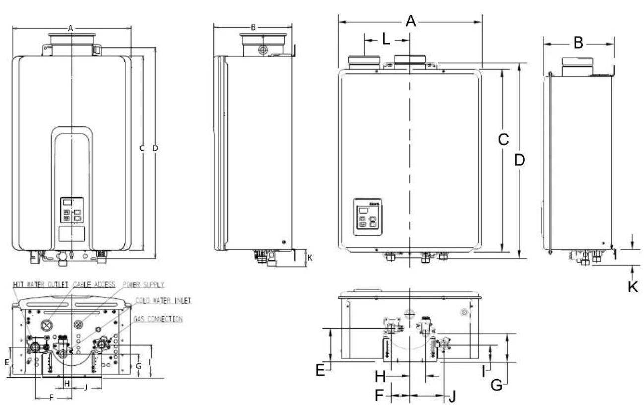
R98LSi, R98LSi-ASME
| DIM | DESCRIPTION | RL75iRL94iin (mm) | R98LSiR98LSi-ASMEin (mm) |
| A Width 14 (355.6) 18.5 (470) | |||
| B Depth * 9.6 (244.5) 9.1 (230.5) | |||
| C Height - Unit 22.9 (582) 23.6 (600) | |||
| D Height - with brackets 25.5 (648.2) 25.2 (639.8) | |||
| E Hot Water Outlet - from wall * 3.6 (91) 4.3 (110) | |||
| F Hot Water Outlet - from center 4.3 (110) 2.4 (61) | |||
| G | Cold Water Inlet - from wall * | 2.8 (70) | 3.7 (94) |
| H Cold Water Inlet - from center | 1.1 (27) | 2.0 (52) | |
| I | Gas Connection - from wall * | 3.9 (99) | 2.2 (56.2) |
| J | Gas Connection - from center | 3.5 (89) | 4.3 (110) |
| K | From base to gas connection | 1.6 (40) | 1.6 (40) |
| From base to cold connection | 2.0 (50) | 2.0 (50) | |
| From base to hot connection | 1.6 (41) | 1.6 (41) | |
* This is the minimum dimension from the wall. The wall bracket is adjustable to allow an additional 1.57 inches (40 mm).
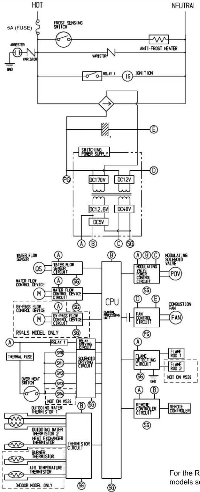
flowchart
graph TD
    subgraph Upper_Circuit
        A["5A (FUSE)"] --> B["FROST SENSING SWITCH"]
        B --> C["ANTI-FROST HEATER"]
        C --> D["VARISTOR"]
        D --> E["RELAY 1"]
        E --> F["IG IGNITION"]
        F --> G["Switching POWER SUPPLY"]
        G --> H["DC170V"]
        G --> I["DC12V"]
        H --> J["DC12.6V"]
        I --> K["DC40V"]
        J --> L["DC5V"]
        K --> M["DC5V"]
        L --> N["A B C SG"]
        M --> O["A B C SOLENOID VALVE FOV"]
        N --> P["WATER FLOW SENSOR"]
        P --> Q["OS"]
        Q --> R["WATER FLOW SENSOR CIRCUIT"]
        R --> S["A SG"]
        S --> T["M WATER FLOW CONTROL DEVICE"]
        T --> U["A SG"]
        U --> V["BY-PASS FLOW CONTROL DEVICE"]
        V --> W["A SG"]
        W --> X["M BY-PASS FLOW CONTROL DEVICE CIRCUIT"]
        X --> Y["SG"]
        Y --> Z["R94LS MODEL ONLY"]
        Z --> AA["A RELAY 1"]
        AA --> AB["SVO"]
        AB --> AC["SVI"]
        AC --> AD["SV2"]
        AD --> AE["SV3"]
        AE --> AF["SV4"]
        AF --> AG["NOT ON V53t"]
        AG --> AH["OUTGOING WATER THERMISTOR 1"]
        AH --> AI["OUTGOING WATER THERMISTOR 2"]
        AI --> AJ["HEAT EXCHANGER THERMISTOR"]
        AJ --> AK["BURNER THERMISTOR"]
        AK --> AL["AIR TEMPERATURE THERMISTOR"]
        AL --> AM["INDOOR MODEL ONLY"]
    end
    subgraph Lower_Circuit
        AN["A B C SOLENOID VALVE FOV"] --> AO["POV"]
        AP["MODULATING VALVE POWER CONTROL CIRCUIT"] --> AQ["SG"]
        AR["FAN CONTROL CIRCUIT"] --> AS["PG"]
        AT["FAN"] --> AU["FAN"]
        AV["A FLAME DETECTING CIRCUIT"] --> AW["FLAME ROD 1"]
        AX["A B REMOTE CONTROLLER CIRCUIT"] --> AY["SMG"]
        AZ["A B REMOTE CONTROLLER"] --> BA["SMG"]
    end
    style Upper_Circuit fill:#f9f,stroke:#333
    style Lower_Circuit fill:#ccf,stroke:#333
    note right of Upper_Circuit
        B: CPU
        C: Control Processing Unit
        D: Power Supply
        E: Switching Supply
        F: DC170V
        G: DC12V
        H: DC12.6V
        I: DC40V
        J: DC5V
        K: CG
    end
    note right of Lower_Circuit
        AA: RELAY DRIVING CIRCUIT
        AB: SOLENOID DRIVING CIRCUIT
        AC: RELAY DRIVING CIRCUIT
        AD: SOLENOID DRIVING CIRCUIT
        AE: RELAY DRIVING CIRCUIT
        AF: NO ON V53t
        AG: OUTGOING WATER THERMISTOR 1
        AH: THERMISTOR CIRCUIT
    end
    note right of Lower_Circuit
        AI: OUTGOING WATER THERMISTOR 2
        AJ: HEAT EXCHANGER THERMISTOR
        AK: AIR TEMPERATURE THERMISTOR
    end
For the R98LSi and R98LSiASME models see the next page.

flowchart
graph TD
    subgraph HOT
        A["3A(FUSE)"] --> B["FROST SENSING SWITCH"]
        B --> C["ANTI-FROST HEATER"]
        C --> D["VARSTOR"]
        D --> E["RELAY 1"]
        E --> F["IG"]
        F --> G["IGNITION"]
        G --> H["E"]
        H --> I["SWITCHING POWER SUPPLY"]
        I --> J["DC170V"]
        I --> K["DC12V"]
        J --> L["DC12.6V"]
        K --> M["DC40V"]
        L --> N["DC5V"]
        M --> O["A B C"]
        N --> P["SG"]
        O --> Q["PG"]
        P --> R["PG"]
        Q --> S["CPU CENTRAL PROCESSING UNIT"]
        R --> T["MODULATING VALVE/POWER CONTROL CIRCUIT"]
        T --> U["POV"]
        V["WATER FLOW SENSOR"] --> W["A"]
        W --> X["WATERFLOW SENSOR CIRCUIT"]
        X --> Y["SG"]
        Y --> Z["A"]
        Z --> AA["WATER FLOW CONTROL DEVICE"]
        AA --> AB["M"]
        AB --> AC["WATERFLOW CONTROL DEVICE CIRCUIT"]
        AC --> AD["SG"]
        AD --> AE["BY-PASS FLOW CONTROL DEVICE"]
        AE --> AF["M"]
        AF --> AG["BY-PASS FLOW CONTROL DEVICE CIRCUIT"]
        AG --> AH["SG"]
        AH --> AI["BY-PASS SERVO MODEL ONLY"]
        AI --> AJ["A"]
        AJ --> AK["RELAY 1"]
        AK --> AL["THERMAL FUSE"]
        AL --> AM["OVERHEAT SWITCH"]
        AM --> AN["SV"]
        AN --> AO["SV"]
        AO --> AP["SV"]
        AP --> AQ["SV"]
        AQ --> AR["SV"]
        AR --> AS["B"]
        AS --> AT["OUTGOING WATER THERMISTOR"]
        AT --> AU["HEAT EXCHANGER THERMISTOR"]
        AU --> AV["AIR TEMPERATURE THERMISTOR"]
        AV --> AW["SG"]
        AW --> AX["INDOOR MODEL ONLY"]
    end

    subgraph NEUTRAL
        B --> A
        C --> C
        D --> C
        E --> C
        F --> C
        G --> C
        H --> C
        I --> C
        J --> C
        K --> C
        L --> C
        M --> C
        N --> C
        O --> C
        P --> C
        Q --> C
        R --> C
        S --> C
        T --> C
        U --> C
        V --> C
        W --> C
        X --> C
        Y --> C
        Z --> C
        AA --> C
        AB --> C
        AC --> C
        AD --> C
        AE --> C
        AF --> C
        AG --> C
        AH --> C
        AI --> C
        AJ --> C
        AK --> C
        AL --> C
        AM --> C
        AN --> C
        AO --> C
        AP --> C
        AQ --> C
        AR --> C
        AS --> C
    end
Consumer Support
Warranty Information
The installer is responsible for your water heater's correct installation.
Please complete the information below to keep for your records:
Purchased from: ____
Address: ____ Phone: ____ ____
Date of Purchase: ____
Model No.: ____
Serial No.:
Installed by: ____ Installer's License No.: ____
Address: ____ Phone: ____
Date of Installation: ____
Limited Warranty
What is covered?
This Warranty covers any defects in materials or workmanship when the product is installed and operated according to Rinnai written installation instructions, subject to the terms within this Limited Warranty document. This Warranty applies only to products that are installed correctly. Improper installation may void this Warranty. Rinnai strongly suggests that you use a state qualified or licensed installer who has attended a Rinnai product knowledge class before installing this water heater. This Warranty extends to the original purchaser and subsequent owners, but only while the product remains at the site of the original installation. This Warranty only extends through the first installation of the product and terminates if the product is moved or reinstalled at a new location.
How long does coverage last?
| Item | Period of Coverage (from date of purchase) | ||
| Residential Applications | Used with Rinnai Air Handler for domestic heating and water | Commercial Applications including radiant heating | |
| Heat Exchanger 12 years * | 10 years * † 5 years * | ||
| All Other Parts and Components | 5 years * | 5 years * † | 5 years * |
| Reasonable Labor | 1 year | ||
* Note: Period of coverage is reduced to 3 years from date of purchase when used as a circulating water heater within a hot water circulation loop, where the water heater is in series with a circulation system and all circulating water flows through the water heater, and where an on-demand recirculation system is not incorporated.
On-demand recirculation is defined as a hot water recirculating loop or system that utilizes existing hot and cold lines or a dedicated return line, and only activates when hot water is used. It can be activated by a push button, motion sensor, or voice activation but not by a temperature sensor. A timer added to a standard recirculating pump is not considered as on-demand.
There is no warranty coverage on product installed in a closed loop application, commonly associated with space heating only applications.
Use of an MCC-91 controller in a residential dwelling will reduce the warranty coverage to that of a commercial warranty application (except when an MCC-91 is used with a Rinnai Hydronic Air Handler).
The integrated controller on indoor models has a 1 year warranty on parts.
† Note: Period of coverage is reduced to 5 years from date of purchase if the Rinnai water heater temperature setting exceeds 160^ F ( 71^ C).
What will Rinnai do?
Rinnai will repair or replace the covered product or any part or component that is defective in materials or workmanship as set forth. Rinnai will pay reasonable labor charges associated with the repair or replacement of any such part or component. All repair parts must be genuine Rinnai parts. All repairs or replacements must be performed by an individual or servicing company that is properly trained, state qualified or licensed to do the type of repair.
Replacement of the product may be authorized by Rinnai only. Rinnai does not authorize any person or company to assume for it any obligation or liability in connection with the replacement of the product. If Rinnai determines that repair of a product is not possible, Rinnai will replace the product with a comparable product at Rinnai's discretion. If a component or product returned to Rinnai is found to be free of defects in material or workmanship, or damaged by improper installation or damaged during return shipping, the warranty claim for product, parts and labor may be denied.
How do I get service?
You must contact a state qualified/licensed contractor or authorized service provider for the repair of a product under this Warranty. For the name of a qualified/authorized service provider please contact your place of purchase, visit the Rinnai website (www.rinnai.us), call Rinnai at 1-800-621-9419 or write to Rinnai at 103 International Drive, Peachtree City, Georgia 30269.
Proof of purchase is required to obtain warranty service. You may show proof of purchase with a dated sales receipt, or by registering within 30 days of purchasing the product. To register your tankless water heater, please visit www.rinnairegistration.com. For those without internet access, please call 1-866-RINNAI1 (746-6241). Receipt of Registration by Rinnai will constitute proof-of-purchase for this product. However, Registration is not necessary in order to validate this Warranty.
What is not covered?
This Warranty does not cover any failures or operating difficulties due to the following:
- accident, abuse, or misuse
- alteration
- misapplication
- force majeure
- improper installation (such as but not limited to inadequate water quality, condensate damage, improper venting, incorrect gas type, incorrect gas or water pressure, or absence of a drain pan under the appliance)
- improper maintenance (such as but not limited to scale build-up, freeze damage, or vent blockage)
- incorrect sizing
- any other causes other than defects in materials or workmanship
This Warranty does not apply to any product whose serial number or manufacture date has been defaced. This Warranty does not cover any product used in an application that uses chemically treated water such as a pool or spa heater. This appliance is suitable for filling large or whirlpool bath tubs with potable water. Refer to the Water Quality Section in the Operation and Installation Manual.
Limitation on warranties
No one is authorized to make any other warranties on behalf of Rinnai America Corporation. Except as expressly provided herein, there are no other warranties, expressed or implied, including, but not limited to warranties of merchantability or fitness for a particular purpose, which extend beyond the description of the warranty herein and further Rinnai shall not be liable for indirect, incidental, special, consequential or other similar damages that may arise, including lost profits, damage to person or property, loss of use, inconvenience, or liability arising from improper installation, service or use. Some states do not allow the exclusion or limitation of incidental or consequential damages, so the above limitation may not apply to you.
Any implied warranties of merchantability and fitness arising under state law are limited in duration to the period of coverage provided by this limited Warranty, unless the period provided by state law is less. Some states do not allow limitations on how long an implied Warranty lasts, so the above limitation may not apply to you.
This Warranty gives you specific legal rights, and you may also have other rights which vary from state to state.
State Regulations
NOTICE BEFORE INSTALLATION
Rinnai direct-vent appliance must be installed by a state qualified or licensed contractor and a properly trained Rinnai Installer. If you are not properly trained, you must not install this unit.
IMPORTANT: In the State of Massachusetts (248 CMR 4.00 & 5.00)
For all side wall horizontally vented gas fueled equipment installed in every dwelling, building or structure used in whole or in part for residential purposes, including those owned or operated by the Commonwealth and where the side wall exhaust vent termination is less than seven (7) feet above finished grade in the area of the venting, including but not limited to decks and porches, the following requirements shall be satisfied:
-
INSTALLATION OF CARBON MONOXIDE DETECTORS. At the time of installation of the side wall horizontal vented gas fueled equipment, the installing plumber or gasfitter shall observe that a hard wired carbon monoxide detector with an alarm and battery back-up is installed on the floor level where the gas equipment is to be installed. In addition, the installing plumber or gasfitter shall observe that a battery operated or hard wired carbon monoxide detector with an alarm is installed on each additional level of the dwelling, building or structure served by the side wall horizontal vented gas fueled equipment. It shall be the responsibility of the property owner to secure the services of qualified licensed professionals for the installation of hard wired carbon monoxide detectors
a. In the event that the side wall horizontally vented gas fueled equipment is installed in a crawl space or an attic, the hard wired carbon monoxide detector with alarm and battery back-up may be installed on the next adjacent floor level.
b. In the event that the requirements of this subdivision can not be met at the time of completion of installation, the owner shall have a period of thirty (30) days to comply with the above requirements; provided, however, that during said thirty (30) day period, a battery operated carbon monoxide detector with an alarm shall be installed. -
APPROVED CARBON MONOXIDE DETECTORS. Each carbon monoxide detector as required in accordance with the above provisions shall comply with NFPA 720 and be ANSI/UL 2034 listed and IAS certified.
-
SIGNAGE. A metal or plastic identification plate shall be permanently mounted to the exterior of the building at a minimum height of eight (8) feet above grade directly in line with the exhaust vent terminal for the horizontally vented gas fueled heating appliance or equipment. The sign shall read, in print size no less than one-half (1/2) inch in size, "GAS VENT DIRECTLY BELOW. KEEP CLEAR OF ALL OBSTRUCTIONS".
-
INSPECTION. The state or local gas inspector of the side wall horizontally vented gas fueled equipment shall not approve the installation unless, upon inspection, the inspector observes carbon monoxide detectors and signage installed in accordance with the provisions of 248 CMR 5.08(2)(a)1 through 4.
www.rinnairegistration.com
(ANSI Z21.10.3, CSA 4.3 60
text_image
Chaud BrûlureInstallation Instructions
ProTech Systems, Inc.
Metal-Fab Inc.
natural_image
Technical line drawing of a mechanical assembly with pipe connection and rotation arrow (no text or symbols)text_image
Installations) 3 in (75 mm) minimum 3 in (75 mm) minimumnatural_image
Technical diagram of a mechanical component with concentric circles and ventilation slots (no text or symbols)Support

natural_image
Technical diagram of a mechanical component with concentric circles and measurement indicators (no text or symbols)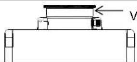
natural_image
Simple line drawing of a room interior with bookshelves and a table, enclosed in a circle (no text or symbols)
natural_image
Pure technical line drawing of a mechanical assembly without any text, numbers, or symbols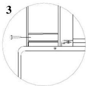
natural_image
Technical line drawing of a mechanical assembly with no visible text or symbols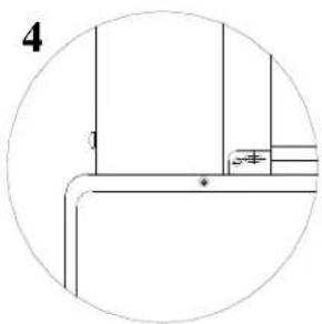
natural_image
Pure technical line drawing of a mechanical assembly without any text, numbers, or symbolsRinnai's other fine products
EXPERIENCE OUR INNOVATION™

natural_image
Two identical metallic industrial gas washing machines shown from different angles (no text or symbols visible)Tankless Water Heaters
• Residential and Commercial Applications
• Continuous Hot Water
• ENERGY STAR ^® qualified models
- Up to 9.8 GPM
• Internal or External Installation
• Digital Temperature Control
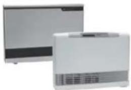
natural_image
Two white electronic devices with ventilation grilles, one open and one closed (no visible text or symbols)Direct Vent Furnaces
• High Efficiency
• Cool-to-the-touch Cabinet
- Blower Included
• Vent Terminal A Included
• Gas Conversion Kit Included

Direct-Vent Fireplace, RHFE-750ETRA
• Up to 83% AFUE Energy Efficiency
• Zero-Clearance Installation
• Available in Four Options of Fronts
• Remotes and Fan Included
• Gas Conversion Kit Available

natural_image
Four identical stainless steel refrigerators in a row, no visible text or labels on the covers.Hydronic Air Handler
• Designed for Use with Rinnai Systems
• Domestic Hot Water Priority
• Optional Programmable Thermostat
• Zero Clearance to Combustibles
• Accommodates Standard Cased-Coils

Boilers
• Residential and Commercial Applications
• ENERGY STAR ^® qualified models
• Up 96.5% AFUE efficiency
- Compact wall mounted design
• ASME accredited models

natural_image
Two modern stainless steel refrigerators side by side, one emitting a flame or vapor, the other with a handle (no visible text or symbols)Condensing Tankless Water Heaters
• Residential and Commercial Applications
• ENERGY STAR ^® qualified models
• Up 95% thermal efficiency
• Internal or External Installation
- Pair up with the Rinnai Air Handler for efficient home heating
Rinnai Impression - Outdoor Fireplace
- Options include one-sided open, two-sided open, and freestanding
• No electrical requirements
• Propane or convertible to natural gas with conversion kit provided
• Modular construction offers design flexibility
Register your product at www.rinnairegistration.com or call 1-866-RINNAI1 (746-6241)
For information on Rinnai's products contact Rinnai America Corporation
103 International Drive
Peachtree City, GA 30269
TOLL FREE: 1-800-621-9419
FAX: 678-829-1666
www.rinnai.us
VB2528FFU VB2735FFU VA3237FFU
U287-193000)
Printed in Japan

060 00012 32191 3