
CrossChek - Inspection tool RIDGID - Free user manual and instructions
Find the device manual for free CrossChek RIDGID in PDF.
| Product Type | Pneumatic drilling inspection tool |
| Brand | RIDGID |
| Model | CrossChek |
| Category | Inspection tool |
| Compatible bore diameter | From 1¼ to 3" (45 to 75 mm) depending on the SeeSnake system used |
| Overall dimensions | Ø = 1½" (38 mm), L = 25¼" (641 mm) |
| Weight (unit alone) | 1,4 lb (630 g) |
| Weight (for microDrain and microReel) | 1,6 lb (730 g) |
| Power supply | Compressed air (via drill hose for pulling) |
| Main functions | Horizontal bore monitoring, wall inspection, probe location (with SeeSnake) |
| Included accessories | 100 ft (30 m) of rope, 3/32" hex key, user manual |
| Compatible systems | SeeSnake cameras, microDrain, nanoReel, microReel, rM-200 |
| Maintenance and cleaning | Clean traces of dirt and grease before each use, check assembly |
| Safety | Wear safety glasses, do not use under electrical voltage or in explosive atmosphere, depressurize hoses before connection |
| Spare parts and repairability | Service and repair by a RIDGID authorized repairer. Lifetime warranty. |
| Warranty | Lifetime warranty against defects in materials and workmanship |
| Recycling | Recyclable components according to applicable legislation |
Frequently Asked Questions - CrossChek RIDGID
User questions about CrossChek RIDGID
0 question about this device. Answer the ones you know or ask your own.
Ask a new question about this device
Download the instructions for your Inspection tool in PDF format for free! Find your manual CrossChek - RIDGID and take your electronic device back in hand. On this page are published all the documents necessary for the use of your device. CrossChek by RIDGID.
USER MANUAL CrossChek RIDGID
CROSSCHEK™ Inspection System

WARNING!
Read this Operator's Manual carefully before using this tool. Failure to understand and follow the contents of this manual may result in electrical shock, fire and/or serious personalinjury.
- Français - 6
Castellano-pag.13
Table of Contents
Safety Symbols
CROSSCHEK™ Inspection System SafetyWarnings 1
Description, Specifications and Standard Equipment
Description 1
Specifications. 1
Standard Equipment 2
Assembly 2
Pre-Operation Inspection 3
Set-Up and Operation 3
Storage 5
Service and Repair 5
Disposal 5
Lifetime Warranty. Back Cover
*Original Instructions - English
Safety Symbols
In this operator's manual and on the product, safety symbols and signal words are used to communicate important safety information. This section is provided to improve understanding of these signal words and symbols.

This is the safety alert symbol. It is used to alert you to potential personal injury hazards. Obey all safety messages that follow this symbol to avoid possible injury or death.

DANGER
DANGER indicates a hazardous situation which, if not avoided, will result in death or serious injury.

WARNING
WARNING indicates a hazardous situation which, if not avoided, could result in death or serious injury.

CAUTION
CAUTION indicates a hazardous situation which, if not avoided, could result in minor or moderate injury.
NOTICE
NOTICE indicates information that relates to the protection of property.

This symbol means read the operator's manual carefully before using the equipment. The operator's manual contains important information on the safe and proper operation of the equipment.

This symbol means always wear safety glasses with side shields or goggles when handling or using this equipment to reduce the risk of eye injury.
CROSSCHEK™ Inspection System SafetyWarnings
WARNING
This section contains important safety information that is specific to these tools.
Read these precautions carefully before using the RIDGID® CROSSCHEK™ Inspection System to reduce the risk of electrical shock or other serious personal injury.
SAVE THESE INSTRUCTIONS!
Keep this manual with the equipment for use by the operator.
- Do not use with pressurized hoses. Connect and disconnect pressure-free hoses only. Pressurized hoses can whip, causing striking and other serious injuries. Always turn OFF the compressor and bleed all air before connecting or disconnecting hoses.
- Do not use in the presence of energized electrical systems. This will reduce the risk of electrical shock.
- Do not operate in explosive atmospheres, such as in the presence of flammable liquids, gases, or dust. Tools can create sparks which may ignite the dust or fumes.
- Always use appropriate personal protective equipment while handling and using the CROSSCHEK Inspection System. Appropriate personal protective equipment always includes safety glasses, and may include equipment such as gloves, face shields, goggles, protective clothing, respirators and steel-toed footwear.
- Follow instructions on proper use of this equipment. Do not use for other purposes. Other uses or modifying this equipment for other applications may increase the risk of serious injury.
- Read and understand the instructions and warnings for all equipment being used including boring tools, cameras and reels before operating the CROSS-CHEK Inspection System. Failure to follow all instructions and warnings may result in property damage or serious personal injury.
The EC Declaration of conformity (890-011-320.10) will accompany this manual as a separate booklet when required.
If you have any question concerning this RIDGID® product:
- Contact your local RIDGID distributor.
- Visit www.RIDGID.com or www.RIDGID.eu to find your local RIDGID contact point.
- Contact RIDGID Technical Services Department at rtctechservices@emerson.com, or in the U.S. and Canada call (800) 519-3456.
Description, Specifications and Standard Equipment
Description
The RIDGID® CROSSCHEK Inspection System is designed for use with the SeeSnake® microDrain™, nanoReel, microReel and rM-200 In spection System. It is used to inspect the straight bores produced by pneumatic underground piercing/boring tools.
The CROSSCHEK Inspection System mounts to the camera head and pushrod. Once a bore is completed, the air hose is attached to the CROSSCHEK Inspection System and used to pull the camera head through the bore for inspection. Once the inspection is completed, a rope is used to retrieve the unit from the bore and pull the utility to be installed into place.
Specifications
Bore Capacity
nanoReel 13/4" to 3" (45 to 75mm) Diameter
microDrain, microReel &
rM-200. 2" to 3" (50 to 75mm) Diameter
Inspection Length....Based on SeeSnake System
Dimension 1/2" D x 2'5" L
(38mm D × 641mm L)
Weight
CROSSCHEK unit
only 1.4 lb (0.63 kg)
Standard Equipment
The RIDGID CROSSCHEK Inspection System comes with the following items:
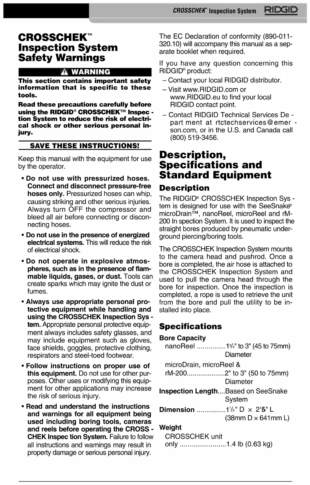
CROSSCHEK Inspection System, (See Figure 1)
100^ (30m) of Rope, 3 / 32 Hex Wrench
Operator's Manual Pack
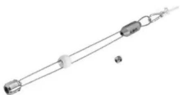
Figure 1-CROSSCHEK Inspection System
NOTICE The CROSSCHEK Inspection System and SeeSnake equipment is used to inspect bores produced by pneumatic under-ground piercing/boring tools. The use of this system does not guarantee the detection of cross bores or other bore features. The action of moving this equipment through the bore may cause the bore to deform or collapse which could cause the bore to be unusable or trap and damage the inspection equipment, requiring the equipment to be dug up to be removed.
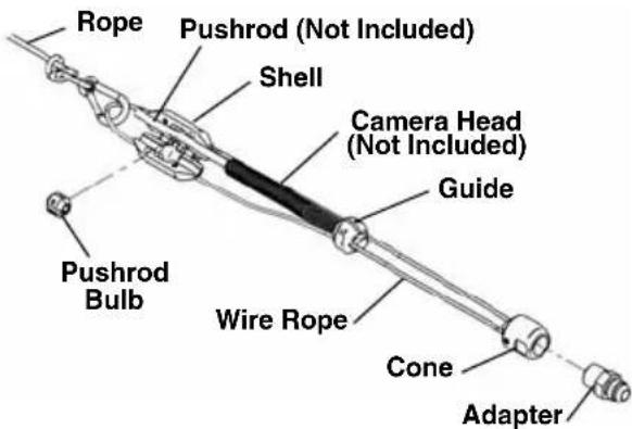
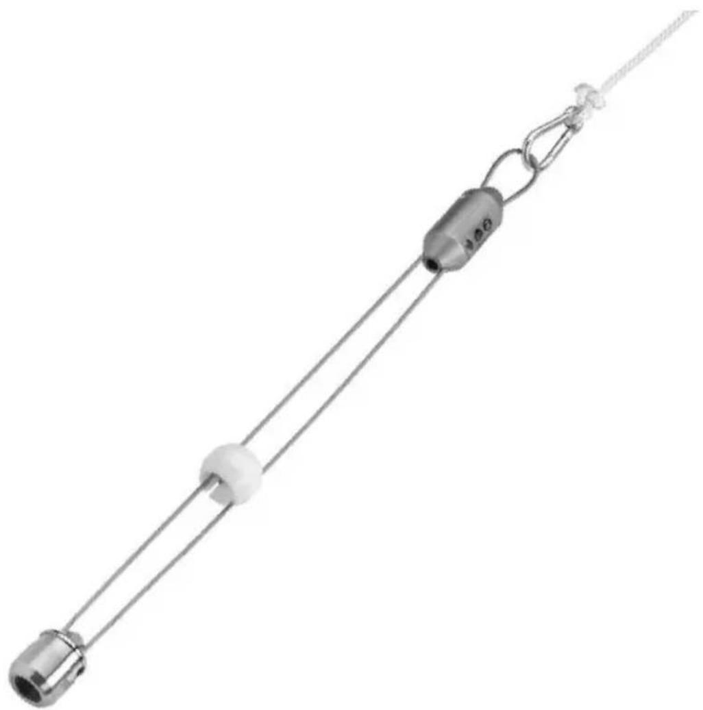
Figure 2 - CROSSCHEK Inspection System
Assembly
WARNING
To reduce the risk of serious injury during use, follow these procedures for proper assembly.
- Make sure to use the correct CROSS
CHEK unit for your system (microDrain™, nanoReel, microReel and rM-200). The diameter and color of the guide will determine which camera system the CROSS-CHEK unit can be used on. (See Figure 3.)
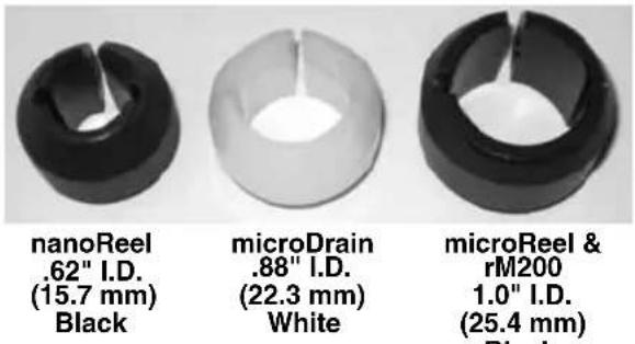
Figure 3
- Securely install the adapter into the cone (Figure 4). The adapter allows attachment of the air hose to the CROSSCHEK Inspection System. The CROSSCHEK In specion System can then be pulled through the bore with the air hose, and the utility (pipe, cable, etc.) can be pulled back through the bore after the inspection with the CROSSCHEK In specion System. Other adapters can be installed as long as they have a 1/2'' NPT male thread for attachment.
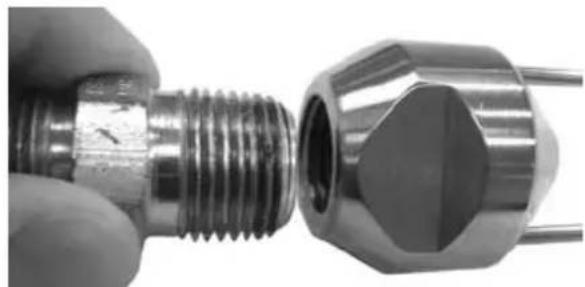
Figure 4 - Installing Adapter Into Cone
- Place the bulb halves around the pushrod 1.5'' (38mm) from the end of the camera spring. Insert and securely tighten the two screws. The bulb halves should securely grip the camera pushrod. A small gap between the halves is acceptable as long as the pushrod is held securely. Do not damage the pushrod.
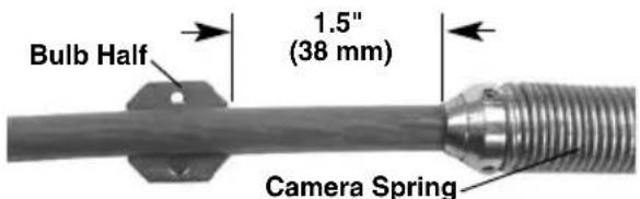
Figure 5 - Position Bulb On Pushrod
- Open the pushrod shell on the CROSS-CHEK unit and place the pushrod bulb, (with pushrod attached), into the opening making certain the grooves in the bulb line up with the wire rope. (Figure 6) Close the shell and tighten the two screws.
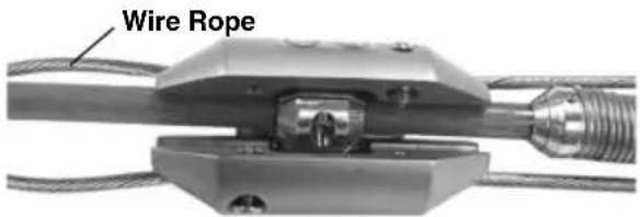
Figure 6 - Locate Pushrod Bulb In Shell
- Slide the guide onto the camera head making sure the wire rope is in the grooves in the guide. Place the guide onto the camera head so that approximately 18 (3.2mm) of the camera head is exposed and tighten the clamp screw (Figure 7).
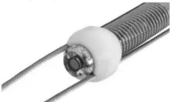
Figure 7 - Installing Guide On Camera Head
- Securely tie the rope to the spring clip and attach to the wire rope loop as shown in Figure 8.
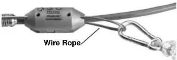
Figure 8 - Attachment of Rope
Pre-Operation Inspection
WARNING
Before each use, inspect your CROSS-CHEK Inspection System and correct any problems to reduce the risk of injury and prevent tool damage.
- Clean any oil, grease or dirt from the CROSSCHEK Inspection System including the cone and adapter.
- Check that the correct adapter is fitted for the type of air hose available.
-
Inspect the CROSSCHEK Inspection System for the following:
-
Proper assembly, maintenance and com pleteness.
- Any broken, worn, missing, misaligned or binding parts.
- Presence and readability of the warning label (Figure 9).
- Any other condition which may prevent safe and normal operation.
If any problems are found, do not use the equipment until the problems have been repaired.


Figure 9 - Warning Label
- Inspect and maintain any other equipment being used per its instructions to make sure it is functioning properly.
Set-Up and Operation
WARNING

Set up and operate the CROSSCHEK In-spection System and work area according to these procedures to reduce the risk of injury from electric shock, entanglement and other causes, and to prevent tool damage.
- Set up and use the underground piercing/boring tool as per its instructions.
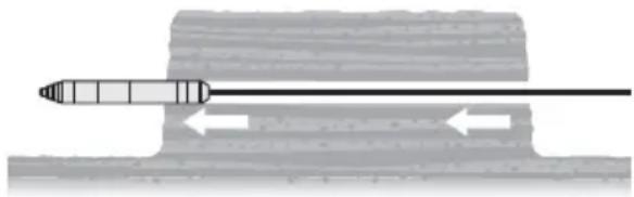
Figure 10 - Bore Made In Soil
- Once the bore is complete, turn off the air supply and wait for pressure to bleed out of the tool and hose. Depressurize the air hose and remove the piercing tool from the air hose as per the piercing tool instructions.
- Examine the bore and make sure that the CROSSCHEK Inspection System is the appropriate tool for the application. The bore should be between 1^3/4 (45mm) and 3^ (75mm) and generally straight. The bore should be self-supporting - soil should not be falling into the bore. This can prevent passage of the CROSSCHEK Inspection System and could damage the equipment.
- Confirm that the CROSSCHEK Inspection System is properly assembled and inspected.
- Securely connect the air hose to the adap ter on the cone of the CROSSCHEK Inspection System (Figure 11). Air hose must have a rotating swivel connection to prevent binding and kinking. Do not twist CROSSCHEK/Pushrod while attaching air hose.
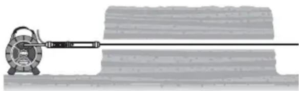
Figure 11 - Connect Air Hose To The CROSS-CHEK Inspection System
- Switch ON the Reel and Camera as per its instructions.
- Operating the CROSSCHEK Inspection System generally requires two people - one person at each end of the bore. Two-way radios or similar devices may be needed to coordinate the movement of the CROSSCHEK Inspection System through the bore. Slowly pull the air hose back through the bore, pulling the in
spection equipment behind it. As the air hose is pulled through the bore, carefully feed the camera pushrod and rope into the bore to reduce the risk of bore damage. Do not force the CROSSCHEK Inspection System through the bore, this could damage the equipment or cause the hole to collapse.
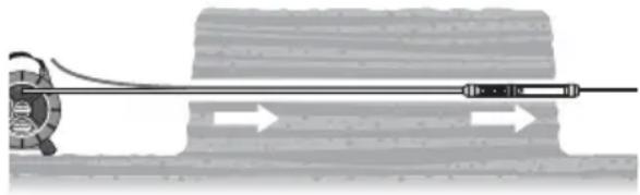
Figure 12 - CROSSCHEK Inspection System Pulled Through With Air Hose
As the camera moves through the bore, carefully monitor the bore walls. If at any time, you see any indication that the bore has contacted electrical, natural gas or other systems that could be hazardous, move away from the bore area and use proper precautions for the hazard. If needed, repeat inspection in any suspect areas.
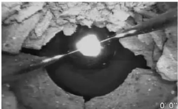
Figure 13 - Typical Crossbore Into Sewer Line
RIDGID SeeSnake systems are equipped with a Sonde (In-Line Transmitter) just behind the camera head. If equipped with a Sonde, a locating unit can be used to detect the Sonde and locate features in the bore being inspected. See the "Lo cating the Sonde" section of your SeeSnake system manual.
If at any time, the bore collapses around the CROSSCHEK Inspection System, camera, pushrod or any other part of the system, stop pulling the unit. Con tinued pulling of the unit could damage the equipment. If the equipment becomes trapped in the bore, it may need to be dug up to be removed.
- When the Inspection equipment comes out through the bore, remove the air hose. If needed, attach the utility (pipe, cable, etc.) to the CROSSCHEK Inspection System with appropriate adapters (Fig ure 14). Do not twist CROSSCHEK/Push rod while attaching utility.
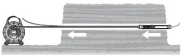
Figure 14 - Connect Utility Line To CROSS-CHEK Inspection System
- Using the rope, pull the CROSSCHEK Inspection System back through the bore with slow, steady force (Figure 15). Do not use excessive force, this could damage the equipment. If desired, the inspection can be repeated as the unit is pulled back. This may allow better inspection results.
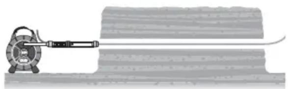
Figure 15 - Utility Line Pulled Through Bore
- Once the inspection is complete, disconnect the CROSSCHEK Inspection System from the utility.
Storage
To prevent damage, the CROSSCHEK In-spection System should be removed from the camera system when storing.
Service and Repair
WARNING
Improper service or repair can make the CROSSCHEK Inspection System unsafe to operate.
Service and repair of the RIDGID CROSS-CHEK Inspection System must be performed by a RIDGID® Independent Authorized Service Center.
For information on your nearest RIDGID In - dependent Service Center or any service or repair questions:
- Contact your local RIDGID distributor.
- Visit www.RIDGID.com or www.RIDGID.eu to find your local RIDGID contact point.
- Contact RIDGID Technical Services Department at rtctechservices@emerson.com, or in the U.S. and Canada call (800) 519-3456.
Disposal
Parts of the RIDGID CROSSCHEK Inspection System contain valuable materials and can be recycled. There are companies that specialize in recycling that may be found locally. Dispose of the components in compliance with all applicable regulations. Contact your local waste management authority for more information.
CONSERVEZ CES INSTRUCTIONS!
microDrain, microReel &
rM-200 .de 2" à 3"
(50 à 75 mm)
nanoReel 13/4" a 3" (45 a 75 mm)
microDrain, microReel y rM-200 2" a 3" (50 a 75 mm) O
Alcance de la
inspeccion.......segun el Sistem SeeSnake que se use
Dimensiones 1 12 '' x 2514 '' largo (38mm x 641mm L)
Peso CROSSCHEK solamente 1,4 lb (0,63 kg)
Equipo estandar
El Sistema de inspections CROSSCHEK cons - ta de:
RIDGID*tools are warranted to be free of defects in workmanship and material.
How long coverage lasts
This warranty lasts for the lifetime of the RIDGID tool. Warranty coverage ends when the product becomes unusable for reasons other than defects in workmanship or material.
How you can get service
To obtain the benefit of this warranty, deliver via prepaid transportation the complete product to RIDGE TOOL COMPANY, Elyria, Ohio, or any authorized RIDGID INDEPENDENT SERVICE CENTER. Pipe wrenches and other hand tools should be returned to the place of purchase.
What we will do to correct problems
Warranted products will be repaired or replaced, at RIDGE TOOL'S option, and returned at no charge; or, if after three attempts to repair or replace during the warranty period the product is still defective, you can elect to receive a full refund of your purchase price.
What is not covered
Failures due to misuse, abuse or normal wear and tear are not covered by this warranty. RIDGE TOOL shall not be responsible for any incidental or consequential damages.
How local law relates to the warranty
Some states do not allow the exclusion or limitation of incidental or consequential damages, so the above limitation or exclusion may not apply to you. This warranty gives you specific rights, and you may also have other rights, which vary, from state to state, province to province, or country to country.
No other express warranty applies
This FULL LIFETIME WARRANTY is the sole and exclusive warranty for RIDGID products. No employee, agent, dealer, or other person is authorized to alter this warranty or make any other warranty on behalf of the RIDGE TOOL COMPANY.

Parts are available online at RIDGIDParts.com

Ridge Tool Company
400 Clark Street
Elyria, Ohio 44035-6001
U.S.A.
Ce qui est couvert
We Build Reputations RIDGID

EMERSON
Commercial & Residential Solutions


- CROSSCHEK™ Inspection System
- WARNING!
- Table of Contents
- Description, Specifications and Standard Equipment
- Safety Symbols
- DANGER
- WARNING
- CAUTION
- NOTICE
- CROSSCHEK™ Inspection System SafetyWarnings
- SAVE THESE INSTRUCTIONS!
- Description
- Specifications
- Bore Capacity
- Weight
- Standard Equipment
- Assembly
- Pre-Operation Inspection
- Set-Up and Operation
- Storage
- Service and Repair
- Improper service or repair can make the CROSSCHEK Inspection System unsafe to operate.
- Disposal
- CONSERVEZ CES INSTRUCTIONS!
- Equipo estandar
- How long coverage lasts
- How you can get service
- What we will do to correct problems
- What is not covered
- How local law relates to the warranty
- No other express warranty applies
- Parts are available online at RIDGIDParts.com
- Ridge Tool Company
- Ce qui est couvert
- We Build Reputations RIDGID
Brand : RIDGID
Model : CrossChek
Category : Inspection tool