
K6200 - Steam cleaner RIDGID - Free user manual and instructions
Find the device manual for free K6200 RIDGID in PDF.

| Product Type | Electric drain cleaner (drain cleaner) |
| Brand | RIDGID |
| Model | K6200 |
| Intended Use | Drain cleaning of 3 to 6 inch diameter pipes |
| Cleaning Capacity | Up to 200 feet (60 m) |
| Drum Capacity | 100 feet (30.5 m) of 5/8 inch cable |
| Motor | Universal reversible AC |
| Voltage | 115 V |
| Frequency | 60 Hz |
| Current | 5.6 A |
| Power | 4/10 HP (0.4 HP) |
| Rotation Speed | 285 rpm |
| Feed System | Automatic with lever, speed 0 to 28 ft/min (0 to 8.5 m/min) |
| Weight (machine + cable) | 180 lb (81.6 kg) |
| Dimensions (L x W x H) | 75 x 48 x 110 cm (29.5 x 19 x 43.5 in) |
| Drum Material | Molded polyethylene |
| Control | Pneumatic foot pedal on/off |
| Safety | GFCI on cord, stabilizing stand, torque limiter |
| Included Accessories | T-406 grease cutter, 2-blade cutters 2, 3, 4 in, gloves, tool box, leg stands |
| Warranty | Lifetime RIDGID warranty |
| Maintenance | Regular lubrication, rinse drum after each use |
Frequently Asked Questions - K6200 RIDGID
User questions about K6200 RIDGID
0 question about this device. Answer the ones you know or ask your own.
Ask a new question about this device
Download the instructions for your Steam cleaner in PDF format for free! Find your manual K6200 - RIDGID and take your electronic device back in hand. On this page are published all the documents necessary for the use of your device. K6200 by RIDGID.
USER MANUAL K6200 RIDGID
Drain Cleaning Machine
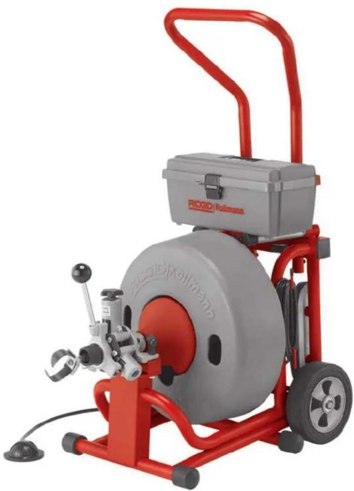
natural_image
Red and gray industrial machine with a circular tire and handle, no visible text or symbols on the device itself.WARNING!
Read this Operator's Manual carefully before using this tool. Failure to understand and follow the contents of this manual may result in extensive property damage and/or serious personal injury.
Table of Contents
Recording Form for Machine Serial Number 1
General Safety Information
Work Area Safety 2
Electrical Safety....2
Personal Safety 2
Tool Use and Care ....3
Service ....3
Specific Safety Information
Drain Cleaner Safety 3
Description, Specifications and Standard Equipment
Description 4
Specifications 4
Standard Equipment....4
Standard Accessories 4
Optional Accessories....4
Cables and Flexible Leaders....5
Tools and Replacement Blades ....5
Machine Assembly
Instructions For Installing Handles ....5
Instructions For Installing Cable 5
Connecting/Disconnecting 5/8" and 3/4" Drum Machine Cable Couplings ....6
Instructions For Installing Loading Wheel and Lifting Hook 6-7
Machine Inspection ....7
Machine and Work Area Set Up 7
Operating Instructions 8
Special Applications Procedure
Main Sewer or Septic Tank Overrun 10
Reverse Operation....10
Loading the Machine On Vehicle 10
Operating Machine In Reclined Position 11
Drum Assembly Removal and Installation....11
Installing Extra Drum (Additional Cable) 11
Pigtail Removal And Installation....12
Proper Tool Selection....12
Accessories
K-3800 Drum Option 13
Installing K-3800 Drum....13
Using K-3800 Drum....13
Maintenance
AUTOFEED Assembly 14
Lubrication....14
Cables 14
Machine Storage....14
Service and Repair ....14
Troubleshooting 15
Lifetime Warranty....Back Cover
K-6200
Drain Cleaning Machine
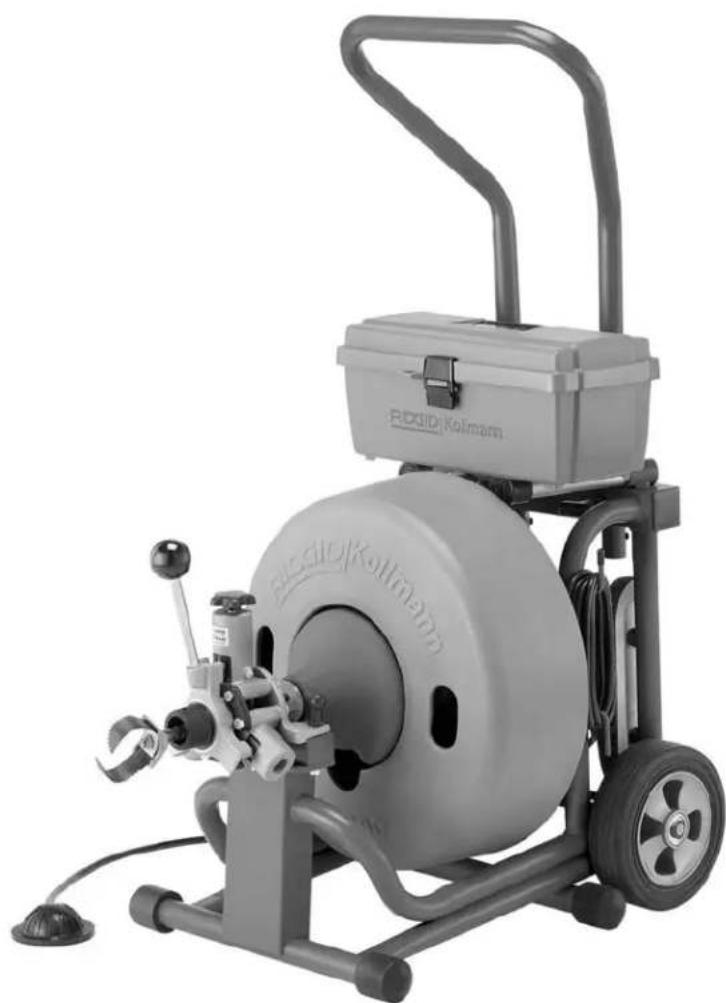
natural_image
Exterior view of a Rodid/Kolmann industrial machine with visible branding and control panel (no text or symbols on the device itself)General Safety Information
WARNING! Read and understand all instructions. Failure to follow all instructions listed below may result in electric shock, fire, and/or serious personal injury.
SAVE THESE INSTRUCTIONS!
Work Area Safety
- Keep your work area clean and well lit. Cluttered benches and dark areas invite accidents.
- Do not operate power tools in explosive atmospheres, such as in the presence of flammable li quids, gases, or dust. Tools create sparks which may ignite the dust or fumes.
- Keep bystanders, children, and visitors away while operating a power tool. Distractions can cause you to lose control.
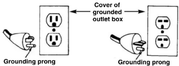
Electrical Safety
- Grounded tools must be plugged into an outlet, properly installed and grounded in accordance with all codes and ordinances. Never remove the grounding prong or modify the plug in any way. Do not use any adapter plugs. Check with a qualified electrician if you are in doubt as to whether the outlet is properly grounded. If the tool should electrically malfunction or break down, grounding provides a low resistance path to carry electricity away from the user.
- Avoid body contact with grounded surfaces such as pipes, radiators, ranges and refrigerators. There is an increased risk of electrical shock if your body is grounded.
- Don't expose electrical tools to rain or wet conditions. Water entering a tool will increase the risk of electrical shock.
- Do not abuse cord. Never use the cord to carry the tools or pull the plug from an outlet. Keep cord away from heat, oil, sharp edges or moving parts. Replace damaged cords immediately. Damaged cords increase the risk of electrical shock.
- When operating a tool outside, use an outdoor extension cord marked "W-A" or "W". These cords
are rated for outdoor use and reduce the risk of electrical shock.
- Use only three-wire extension cords which have three-prong grounding plugs and three-pole receptacles which accept the tool's plug. Use of other extension cords will not ground the tool and increase the risk of electrical shock.
- Use proper extension cords. (See chart.) Insufficient conductor size will cause excessive voltage drop, loss of power.
| Minimum Wire Gauge for Extension Cord | |||
| NameplateAmps Total Length (in feet) | |||
| 0 – 25 26 | - 50 51 – 100 | ||
| 0 – 6 | 18 AWG | 16 AWG | 16 AWG |
| 6 – 10 | 18 AWG | 16 AWG | 14 AWG |
| 10 – 12 | 16 AWG | 16 AWG | 14 AWG |
| 12 – 16 | 14 AWG | 12 AWG | NOT RECOMMENDED |
- Before using, test the Ground Fault Circuit Interrupter (GFCI) provided with the power cord to insure it is operating correctly. GFCI reduces the risk of electrical shock.
- Extension cords are not recommended unless they are plugged into a Ground Fault Circuit Interrupter (GFCI) found in circuit boxes or outlet receptacles. The GFCI on the machine power cord will not prevent electrical shock from the extension cords.
- Keep all electric connections dry and off the ground. Do not touch plugs or tool with wet hands. Reduces the risk of electrical shock.
Personal Safety
- Stay alert, watch what you are doing and use common sense when operating a power tool. Do not use tool while tired or under the influence of drugs, alcohol, or medications. A moment of inattention while operating power tools may result in serious personal injury.
- Dress properly. Do not wear loose clothing or jewelry. Contain long hair. Keep your hair, clothing, and gloves away from moving parts. Loose clothes, jewelry, or long hair can be caught in moving parts.
- Avoid accidental starting. Be sure switch is OFF before plugging in. Carrying tools with your finger on the switch or plugging tools in that have the switch ON invites accidents.
-
Remove adjusting keys or switches before turning the tool ON. A wrench or a key that is left attached to a rotating part of the tool may result in personal injury.
-
Do not over-reach. Keep proper footing and balance at all times. Proper footing and balance enables better control of the tool in unexpected situations.
- Use safety equipment. Always wear eye protection. Dust mask, non-skid safety shoes, hard hat, or hearing protection must be used for appropriate conditions.
Tool Use and Care
- Use clamp or other practical way to secure and support the workpiece to a stable platform. Holding the work by hand or against your body is unstable and may lead to loss of control.
- Do not force tool. Use the correct tool for your application. The correct tool will do the job better and safer at the rate for which it is designed.
- Do not use tool if switch does not turn it ON or OFF. Any tool that cannot be controlled with the switch is dangerous and must be repaired.
- Disconnect the plug from the power source before making any adjustments, changing accessories, or storing the tool. Such preventive safety measures reduce risk of starting tool accidentally.
- Store idle tools out of the reach of children and other untrained persons. Tools are dangerous in the hands of untrained users.
- Maintain tools with care. Keep cutting tools sharp and clean. Properly maintained tools with sharp cutting edges are less likely to bind and are easier to control.
- Check for misalignment or binding of moving parts, breakage of parts, and any other condition that may affect the tool's operation. If damaged, have the tool serviced before using. Many accidents are caused by poorly maintained tools.
- Use only accessories that are recommended by the manufacturer for your model. Accessories that may be suitable for one tool may become hazardous when used on another tool.
- Keep handles dry and clean; free from oil and grease. Allows for better control of the tool.
Service
- Tool service must be performed only by qualified repair personnel. Service or maintenance performed by unqualified repair personnel could result in injury.
- When servicing a tool, use only identical replacement parts. Follow instructions in the Maintenance Section of this manual. Use of unauthorized parts or failure to follow maintenance instructions may create a risk of electrical shock or injury.
Specific Safety Information
WARNING
Read this Operator's Manual carefully before using the RIDGID K-6200 Drain Cleaner. Failure to understand and follow the contents of this manual may result in electrical shock, fire and/or severe personal injury.
Contact Ridge Tool Technical Service Department at rttechservices@emerson.com, or in the U.S. and Cana - da call (800) 519-3456.
Drain Cleaner Safety
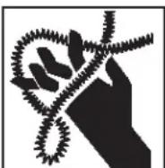
- Wear gloves provided with the machine. Never grasp a rotating cable with a rag or loose fitting cloth glove. Could become wrapped around the cable and cause serious injury.
- Do not overstress cables. Keep hand on the cable for control when machine is running. Overstressing cables may cause twisting, kinking and result in serious injury.
- Position machine within three feet of inlet. Use Front Guide Hose or properly support exposed cable when it is difficult to locate the machine near the access or clean out. Greater distances can result in cable twisting, kinking or control problems.
- The K-6200 is designed for one person operation. Operator must control foot switch and cable.
- Use foot switch to operate K-6200 while maintaining good footing and balance. Do not operate machine in (REV) reverse. Operating machine in reverse can result in cable damage and is used only to briefly back tool out of an obstruction.
- Keep hands away from rotating drum and guide tube. Do not reach into drum unless machine is unplugged. Hand may be caught in the moving parts resulting in serious injury.
- Use kickstand during operation. The kickstand stabilizes machine to prevent tipping.
- Be careful when using the K-6200 in drains where cleaning compounds or chemicals have been used. Serious burns can result from some drain cleaning compounds.
- Do not operate machine if operator or machine is standing in water. Will increase the risk of electrical shock.
- Wear safety glasses and rubber soled, non-slip shoes. Use of this safety equipment may prevent serious injury.
- Only use the K-6200 to clean drain lines 3" to 6" in diameter. Follow instructions on the use of the machine. Other uses or modifying the drain cleaner for other applications may increase the risk of injury.
Description, Specifications and Standard Equipment
Description
The RIDGID ^® K-6200 Drain Cleaning Machine will clean drain lines 3" to 6" in diameter and up to 200 feet in length. The 4/10 HP universal motor spins ^5/8 cable at 285 RPM. When the cable hits the blockage, the motor gears down automatically to deliver greater power and enhance operator control.
The molded polyethylene drum includes an inner drum that guards against cable flip-over. An integral Ground Fault Interrupter (GFCI) is built into the line cord and a "kickstand" base is provided for machine stability during operation. A pneumatic foot actuator provides ON/OFF control of the motor.
The drum powers a ^5/8 " inner core cable that has a quick change coupling system for connecting or disconnecting tools. The cable is fed in and out of the drain by a AUTO - FEED assembly at a rate of 0-28 feet/min. An integral torque limiter will cause the drum to stop rotating whenever excessive torque is created when the cutting tool attached to the cable hits a snag and stops rotating.
The K-6200 can also be adapted to utilize the K-3800 drum with a 1/2" cable to clean drain lines 2" to 4" in diameter and up to 90' in length.
Specifications
Line Capacity....3" - 6" Lines, Up To 200 feet
Drum Capacity ......100' d/8" Cable
Motor:
Type ......115V/60 Hz, Reversible, Universal AC Motor
Rating....4/10 HP, 285 RPM
Amps 5.6
Weight (Machine &
100 ft of Cable)....180 lbs.
Length 29 ^1/2 "
Height 43.5" (max)
Width 19"
Standard Equipment
Machine Options – AUTOFEED
| Catalog No. | Model No. | Description | |
| 115V | 220-240V | ||
| 95737 | 95852 | K-6200 | Machine w/5/8" Pigtail & Standard Accessories |
| 95732 | — | K-6200 w/C-24 | Machine, Standard Accessories and 5/8" x 100' Inner Core Cable |
| 93557 | — | K-6200 w/C-24-IW | Machine, Standard Accessories and 5/8" x 100' IW Solid Core Cable |
Standard Accessories
• T-406 Grease Blade
• T-411 2" Double Cutter
• T-413 3" Double Cutter
• T-414 4" Double Cutter
- Gloves, Tool Box
- Machine Legs (2)

natural_image
RIDGE Pilotminder toolbox and mechanical tools laid out on a white surface (no text or symbols visible)Figure 1 – Standard Equipment Included In All Machine Options
Optional Accessories
Catalog No. Description
• 95797 Lifting Hook
• 95792 Swivel Loading Wheel Assembly
• 95802 K-6200 Drum Assy. w/ ^5/8 Pigtail
• 95807 K-3800 Drum Assy. w/6200 Adapters
• 95822 K-3800 to K-6200 Adapter Kit Only
• 59982 Cable Rust Inhibitor 1 Qt.
• 59987 Cable Rust Inhibitor 1 Gal.
Cables and Flexible Trap Leaders
| Catalog No. | Model No. | Description | |
| 92460 | C-25 | 25' I.C. Cable (7,6m) | |
| 92465 | C-26 | 50' I.C. Cable (15,2m) | |
| 92470 | C-27 | 75' I.C. Cable (22,9m) | |
| ^5/_8" (16mm) | 43647 | C-24 | 100' I.C. Cable (30,5m) |
| 32737 | C-27HC | 75' Hollow-Core (22,9m) | |
| 58192 | C-24HC | 100' Hollow-Core (30,5m) | |
| 95762 | C-25 IW | 25' I.W. Cable (7,6m) | |
| 95757 | C-26 IW | 50' I.W. Cable (15,2m) | |
| 95752 | C-27 IW | 75' I.W. Cable (22,9m) | |
| ^5/_8" IW (16mm) | 95747 | C-24 IW | 100' I.W. Cable (30,5m) |
| 92555 | T-458 | ^5/_8" x 2' Leader | |
| 44122 | — | ^5/_8" Pigtail |
Tools and Replacement Blades — Fits C-24, C-25, C-26, C-27, C-24 IW, C25 IW, C-26 IW, C-27 IW, C-24HC, C-27HC
| Catalog No. | Model No. | Description | Replacement | ||
| Blade(s) | Holder* | ||||
 | 92485 | T-403 | P-Trap Cutter, 3" | 92835 | 92900 |
| 92490 | T-404 | P-Trap Cutter, 3^1/2 " | 92840 | 92900 | |
| 92495 | T-406 | Spear Blade | 92850 | 92915 | |
 | 92500 | T-407 | Retrieving Auger | — | — |
 | 92505 | T-408 | Sawtooth Cutter | 92890 | 92915 |
 | 51762 | T-409 | H-D Bulb Auger | — | — |
 | 92510 | T-411 | Double Cutter, 2" | 92815 | 92905 |
| 92515 | T-412 | Double Cutter, 2^1/2 " | 92820 | 92905 | |
| 92520 | T-413 | Double Cutter, 3" | 92825 | 92910 | |
| 92525 | T-414 | Double Cutter, 4" | 92830 | 92910 | |
| 92530 | T-416 | Double Cutter, 6" | 92855 | 92910 | |
 | 92535 | T-432 | 3-Blade Cutter, 2" | 92860 | 92895 |
| 92540 | T-433 | 3-Blade Cutter, 3" | 92865 | 92895 | |
| 92545 | T-434 | 3-Blade Cutter, 4" | 92870 | 92895 | |
| 92550 | T-436 | 3-Blade Cutter, 6" | 92875 | 92895 | |
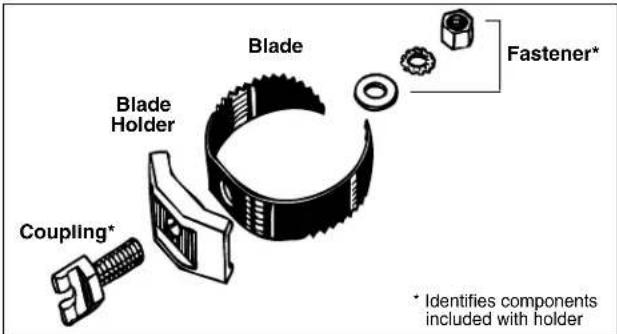
Figure 2 – Tool Assembly
Machine Assembly
WARNING
To prevent serious injury, proper assembly of the Drain Cleaner is required. The following procedures should be followed:
Instructions For Installing Handles
Remove the two (2) screws from handle. Loosen two (2) "T" handles and slide handle into the frame (Figure 5). Replace the two screws in the handle to prevent it sliding out of the frame. Adjust the handle to the desired height and firmly tighten the "T" handles to lock the handle in place.
Instructions For Installing Cable
CAUTION Do not remove bands or staples from cable shipping carton. Cable is under tension and will whip, causing injury.
Retrieve end of cable through the center hole of carton and remove enough cable to connect with drum pigtail. Connect the male coupling of the cable to the pigtail coupling (see Figure 3). Confirm connection is secure. Feed cable into drum.
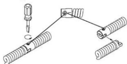
Connecting/Disconnecting 5/8" and 3/4" Drum Machine Cable Couplings
Keep couplings clean and lubricated. Plunger pin must move freely and fully extend to secure connection.
New style - Plunger pin
Screwdriver required.
Connecting
1
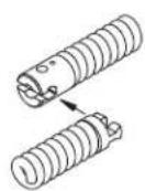
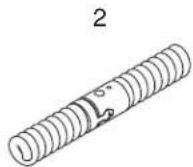
- Slide the couplings together. If needed, depress plunger pin.
- Confirm connection is secure. (plunger pin fully extended).
Disconnecting
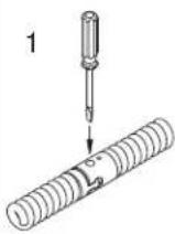
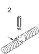
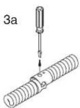
3b
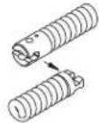
- Insert the screwdriver to depress the plunger pin.
- Push the couplings apart until the male coupling contacts the screwdriver.
- Remove the screwdriver and push the couplings apart.
Old style - Rotating pin
Screwdriver required.
Connecting
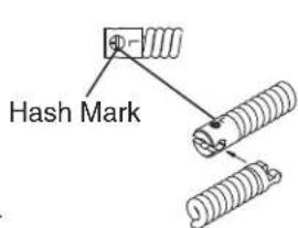
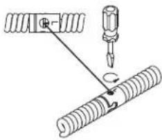
- Slide the couplings together.
- Rotate pin so hash mark is away from end of cable (towards "L" stamped on coupling). Confirm connection is secure.
Disconnecting
natural_image
Pure mechanical diagram showing a screw and spring assembly without any text, numbers, or symbols- Rotate pin so hash mark is towards end of cable (away from "L" stamped on coupling).
- Push the couplings apart.
Figure 3
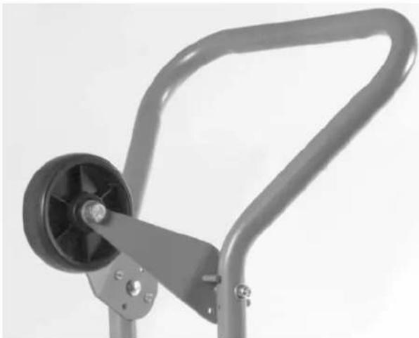
Instructions For Installing Loading Wheel
(Optional Accessory)
- Locate the two pre-drilled holes near the top of the handle.
- Bolt loading wheel to handle using the 516 " carriage bolts and lock nuts as shown in Figure 4.
NOTE! Loading wheel swivels up and down. Raise wheel for loading, lower wheel while transporting or operating machine.
natural_image
Close-up of a mechanical lever mechanism with a black wheel and metallic frame (no text or symbols visible)Figure 4 – Loading Wheel
Instructions For Installing Lifting Hook
(Optional Accessory)
- Locate the pre-drilled hole on the top of the cross beam that holds the motor and gear box.
- Bolt lifting hook into place as shown in Figure 16.
Machine Inspection
WARNING

To prevent serious injury, inspect your Drain Cleaning Machine. The following inspection procedures should be performed before each use.
- Make sure the Drain Cleaning Machine is unplugged and the directional switch is set to the OFF position.
- Make sure the foot switch is present and attached to the Drain Cleaning Machine (Figure 5). Do not operate the machine without a foot switch.
- Inspect the power cord, Ground Fault Circuit Inter-rupter (GFCI) and plug for damage. If the plug has been modified, is missing the grounding prong or if the cord is damaged, do not use the Drain Cleaning Machine until the cord has been replaced.
- Inspect the Drain Cleaning Machine for any broken, missing, misaligned or binding parts as well as any other conditions which may affect the safe and normal operation of the machine. If any of these conditions are present, do not use the Drain Cleaning Machine until any problem has been repaired.
- Lubricate the Drain Cleaning Machine, when necessary, according to the Maintenance Instructions.
- Use tools and accessories that are designed for your drain cleaner and meet the needs of your application. The correct tools and accessories allow you to do the job successfully and safely. Accessories suitable for use with other equipment may be hazardous when used with this drain cleaner.
- Clean any oil, grease or dirt from all equipment handles and controls. This reduces the risk of injury due to a tool or control slipping from your grip.
natural_image
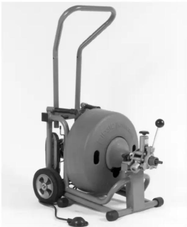
Exterior view of a gray exercise machine with wheels and control panel (no visible text or symbols)Figure 5 – K-6200 Drain Cleaner
- Inspect the cutting edges of your tools. If necessary, have them sharpened or replaced prior to using the Drain Cleaning Machine. Dull or damaged cutting tools can lead to binding and cable breakage.
- Inspect cables and couplings for wear and damage. Cables should be replaced when they become severely worn or corroded. A worn cable can be identified when the outside coils become flat.
WARNING Worn or damaged cables can break causing serious injury.
Machine and Work Area Set-Up
WARNING


To prevent serious injury, proper set-up of the machine and work area is required. The following procedures should be followed to set-up machine:
- Check work area for:
-
Adequate lighting.
• Grounded electrical outlet. -
Clear path to the electrical outlet that does not contain any sources of heat or oil, sharp edges or moving parts that may damage electrical cord.
- Dry place for machine and operator. Do not use the machine while standing in water.
-
Flammable liquids, vapors or dust that may ignite.
-
Position the Drain Cleaning Machine within 3' of sewer inlet.
⚠ WARNING If sewer inlet greater than 3' from the front of the machine, the cable will have a greater tendency to twist or kink. Use a front guide hose or properly support exposed cable.
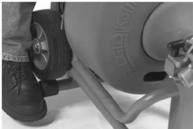
- Set the spring loaded kickstand bar by tilting the machine forward to allow the bar to pivot behind the tires (Figure 6). Make sure the machine rests firmly on the bar before continuing. The tires should not contact the ground.
natural_image
Close-up of a person's lower legs and wheel with visible tire, no text or symbols presentFigure 6 – Setting Kickstand Bar
natural_image
Mechanical device with wheels and a leg, no visible text or symbolsFigure 7 – Releasing Kickstand Bar
WARNING
To prevent tipping during use, machine should rest firmly on the kickstand.
- Position the air foot switch pedal for easy operator accessibility. Machine is designed for one person operation. (Figure 8)
- Make sure FOR/OFF/REV switch is in the OFF position.
- Select and install the proper tool/cutter to the end of the cable. Securely install tool on the end of the cable (See Figure 3). If the connection is not secure, the cutting tool may fall off in use.
- Plug the Drain Cleaning Machine into the electrical outlet, making sure to position the power cord along the clear path selected earlier. If the power cord does not reach the outlet, use an extension cord in good condition.
⚠ WARNING To avoid electric shock and electrical fires, never use an extension cord that is damaged or does not meet the following requirements:
- The cord has a three-prong plug similar to shown in Electrical Safety section.
- The cord is rated as "W" or "W-A" if being used outdoors.
- The cord has sufficient wire thickness (16 AWG below 50'/14 AWG 50'-100'). If the wire thickness is too small, the cord may overheat, melting the cord's insulation or causing nearby objects to ignite.
⚠ WARNING To reduce risk of electric shock, keep all electrical connections dry and off the ground. Do not touch plug with wet hands. Test the Ground Fault Circuit Interrupter (GFCI) provided with the electric cord to insure it is operating correctly. When test button is pushed in, the indicator light should go OFF. Reactivate by pushing the reset button in. If indicator light goes on, the machine is ready to use. If the GFCI does not function correctly, do not use the machine.
Operating Instructions
WARNING


Wear gloves provided with machine. Never grasp a rotating cable with a rag or loose fitting cloth glove that may become wrapped around the cable, causing serious injury.
Always wear eye protection to protect your eyes against dirt and other foreign objects. Wear rubber soled, non-slip shoes.
Always assume the correct operating posture in order to maintain proper balance (Figure 8). Should an unexpected situation arise, this posture provides you with the opportunity to safely keep control of the machine and cable.
- Be sure you can quickly remove your foot from the foot switch.
- Hand must be on the cable to control its twisting action when it hits an obstruction.
-
Keep hands away from rotating drum and guide tube. Do not reach into drum unless machine is unplugged.
-
Loosen the feed knob to ensure AUTOFEED is not engaged. Manually pull a sufficient length of cable out of the drum and manually push the tool and cable into the sewer inlet.
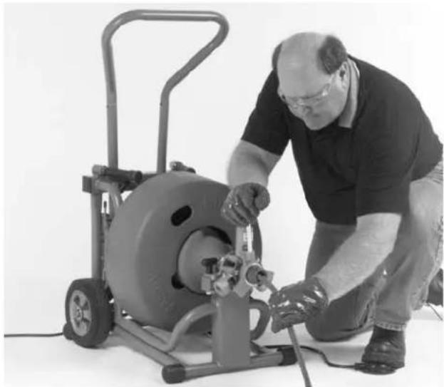
natural_image
Man operating a large industrial machine with tools, no visible text or symbolsFigure 8 – Proper Operating Position
- Move FOR/OFF/REV switch into FOR (forward) position. Do not step on the air foot switch pedal at this time.
- To use AUTOFEED, turn feed knob down until top bearing makes contact with the cable, then turn one full additional turn. Do not over-tighten.
WARNING
Before starting machine, operator's gloved hand must be on the cable.
-
Exert sufficient downward pressure on cable to keep it in sewer line while depressing air foot switch pedal to start cable rotating.
-
Move the feed lever in the opposite direction of the rotating drum to advance the cable (Figure 9). The rate at which the cable is fed (0 - 28' per minute) into the sewer is controlled by the position of the feed lever away from neutral (vertical) position. The further from vertical, the faster the feed rate. Always keep one hand on the cable to feel tension.
-
Continue to feed the cable into the line until resistance or obstruction is encountered. This condition will generally become apparent to the operator as the motor will "lug" down and/or the cable will have a tendency to twist sideways in the operator's hands.
If the cable shows signs that the cutter has stopped rotating, fully reverse feed lever (move handle in the same direction of the drum rotation) to back the cutter away and to relieve the load. Gradually feed the cable into the obstruction, allowing cutter to advance slowly. Occasionally move AUTOFEED lever to neutral to allow cutter to work through the obstruction. If motor turns but the drum stops, the torque limiter is slipping because of excessive force. Pull back on cable to relieve torque and drum will begin to spin.
TIP: If cable continues to get hung up in blockage, discontinue use of the AUTOFEED and work cable by hand.
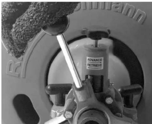
Figure 9 – Feed Lever Operation
- Once flow is established, use running water to wash debris and roots down the drain while finishing the job.
WARNING
Do not allow tension to build up in the cable. This will happen if the cutting tool hits a snag and stops turning, but the motor and its drum continue to rotate. Torque builds until the cable suddenly twists, potentially wrapping around your hand or arm. This
can happen quickly and without warning, so proceed slowly and carefully as you feed the cable into the drain. If tool gets hung up in an obstruction, refer to Reverse Operating Instructions in the Special Procedures section.
- Several passes through thoroughly blocked drain lines are recommended. Start with a grease cutter or 2" blade, or a blade typically 2" smaller than the drain size. After establishing drain flow, increase cutter size to thoroughly clean the lines.
TIP: Know approximately where you are going. Over-running cable into city sewers or septic tanks can cause cable damage and retrieval problems.
NOTE! Additional cable may be added if required. Refer to Special Applications Procedure section.
- To retrieve the cable from the sewer line, move the AUTOFEED handle in the same direction of the drum rotation.
CAUTION Do not put the machine in reverse.
The machine should be kept running during the retrieval process for thorough cleaning.
NOTE! A continuous flush of water should be used to clean the cable and tool as they are retrieved.
- When the tool is just inside the sewer inlet, release the air foot switch pedal and allow the machine to come to a complete stop.
WARNING Never retract tool from sewer inlet while cable is rotating. Tool can whip causing serious injury.
-
Turn FOR/OFF/REV Switch to OFF position and remove cord from power source.
-
Loosen the feed knob and pull the remaining cable and tool from the sewer. Hand feed the cable into the machine.
-
Disengage the spring loaded kickstand bar by tilting the machine forward, forcing the bar forward of the tires. (Figure 7)
Special Procedures
Main Sewer Or Septic Tank Overrun
It is very important to know the approximate distance from inlet to main sewer or septic tank. Over-running cable too far into main sewer or septic tank can allow cables to knot-up and prevent their return through small lines.
Reverse Operation
Running machine in reverse will cause premature failure of cable. Use reverse only to free a tool caught in an obstruction. If this should occur, immediately remove foot from air foot switch pedal and allow machine to come to a full and complete stop. Place FOR/OFF/REV switch to REV (reverse) position. Loosen feed knob. Grasp cable with gloved hands and pull while jogging air foot switch pedal. When tool is dislodged and drum has stopped rotating, place FOR/OFF/REV switch in FOR (forward) position and follow normal operating procedure.
WARNING Never operate this machine in REV (reverse) for any other purpose. Operating in reverse can damage a cable and cause serious injury.
Loading The Machine On Vehicle
Loading Wheel
Optional loading wheel swivels up and down. Raise wheel for loading, lower wheel while transporting or operating machine.
With loading wheel raised, tip machine backwards and rest handle or loading wheel on truck bed. Lift up on front of machine and slide onto truck.
⚠ WARNING Use proper lifting technique – lift with your legs, not your back!!
NOTE! Take care not to damage electrical cord or air foot switch hose.
Lifting Hook
Optional lifting hook can be used to raise and lower the machine into a truck using a hoist. The Machine must be raised by hooking through the hole in the lifting hook.
⚠ WARNING Lifting the machine by the handle or any other part of the machine may result in the machine tipping and/or the part failing. This could result in the machine falling causing serious injury.
NOTE! Take care not to damage electrical cord or air foot switch hose.
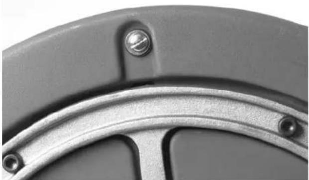
Draining the Drum
Water can be drained from the drum by removing the screw plug located in the rear of the drum (Figure 10) and resting the machine on its back as seen in Figure 11. Be sure the screw drain plug is replaced before transporting the machine.
natural_image
Close-up of a mechanical component with metallic surfaces and bolt holes (no text or symbols visible)Figure 10 – Drum Drain Hole
Operating Machine In Reclined Position
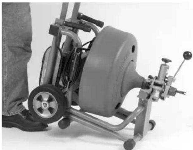
The K-6200 can be operated in the reclined position to access overhead waste lines. As shown in Figure 11, screw the two (2) support legs into the frame. With the kickstand bar in the forward position ahead of the wheels, place the machine so it rests on the support legs and the wheels.
⚠ WARNING If sewer inlet is greater than 3' from the front off the machine, the cable will have a greater tendency to twist or kink. Use a front guide tube or properly support exposed cable.
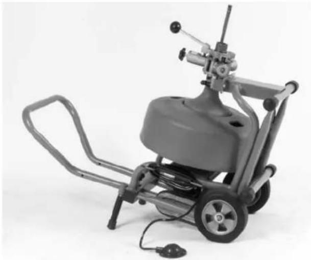
natural_image
Mechanical device with wheels and control panel, no visible text or symbolsFigure 11 - Machine In Reclined Position
Drum Assembly Removal & Installation
WARNING
Make sure FOR/OFF/REV SWITCH is in OFF position and machine is unplugged from power source.
Drum Removal
-
Set kickstand in the operating position to keep the machine from moving.
-
Loosen the top AUTOFEED knob to make sure the top bearing is not in contact with the cable and remove the cutter.
- Loosen the two T-handle mounting knobs located on the drum side of the AUTOFEED assembly. It is not necessary to remove the knobs, just loosen enough to allow the AUTOFEED assembly to slide off the front support. Slide the assembly off the cable.
- The drum assembly can be removed by grasping the drum via the center hole on the drum front and by lifting and sliding the shaft of the assembly out of the gear box.
WARNING Use proper lifting technique – lift with your legs, not your back!!
Drum Installation
- Set the kickstand to keep machine from moving.
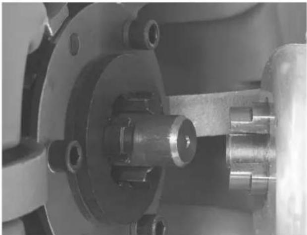
- Grasp the drum assembly via the center hole on the drum front and lift the assembly onto the frame. Slide the shaft of the drum assembly into the gear box. Align the tangs of the drum and gear box assembly and fully engage (Figure 12).
WARNING Use proper lifting technique – lift with your legs, not your back!!
natural_image
Close-up of a mechanical assembly with metallic components and mounting holes (no visible text or symbols)Figure 12 – Installing Drum Assembly Into Gear Box
- Attach AUTOFEED by sliding the assembly onto the cable. Slide assembly onto front support and tighten the two T-handle mounting knobs.
Installing Extra Drum (Additional Cable)
The operator may wish to carry a second drum with cable for runs greater than 100'.
-
Set the kickstand to keep machine from moving.
-
Disconnect the original cable from the pigtail section. Secure the initial cable to keep it from falling into the drain.
- Remove the AUTOFEED assembly as described in Steps 2 – 3 of Drum Assembly Removal section.
- Remove the drum assembly described in Step 4 of Drum Assembly Removal section.
- Place second drum assembly onto the machine by following instructions in Step 2 of Drum Assembly In stal lation section.
- Attach AUTOFEED by sliding the assembly onto the cable. Slide assembly onto front support and tighten the two T-handle mounting knobs.
- Attach the cable from the extra drum to the cable in the drain.
NOTE! Be sure all cable and cutter is spinning in drain before feeding in more cable.
Pigtail Removal and Installation
- Set the kickstand.
- Remove all cable from the drum except the pigtail.
- Remove the AUTOFEED assembly and main drum.
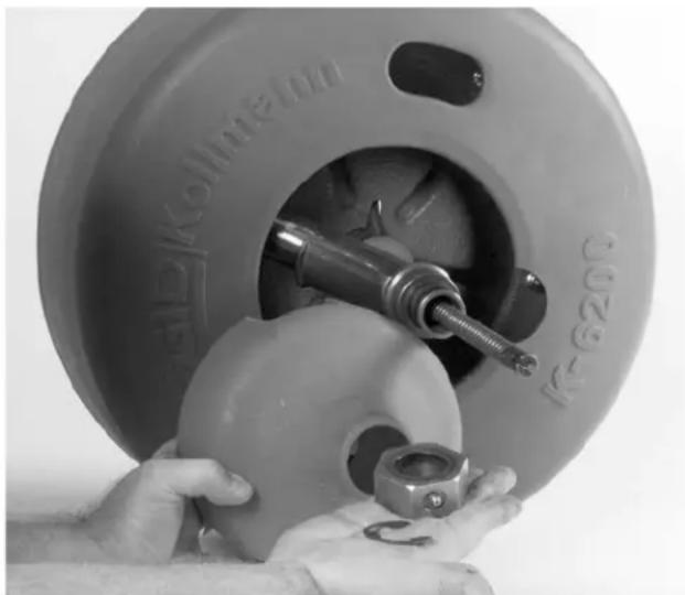
- Remove the outer retaining clip from the guide tube shaft (Figure 13). Slide bearing off the shaft.
natural_image
Close-up of hands operating a mechanical tool inside a cylindrical device (no visible text or symbols)Figure 13 - Remove Retaining Ring and Inner Drum
-
Remove retaining ring holding inner drum in place and remove inner drum.
-
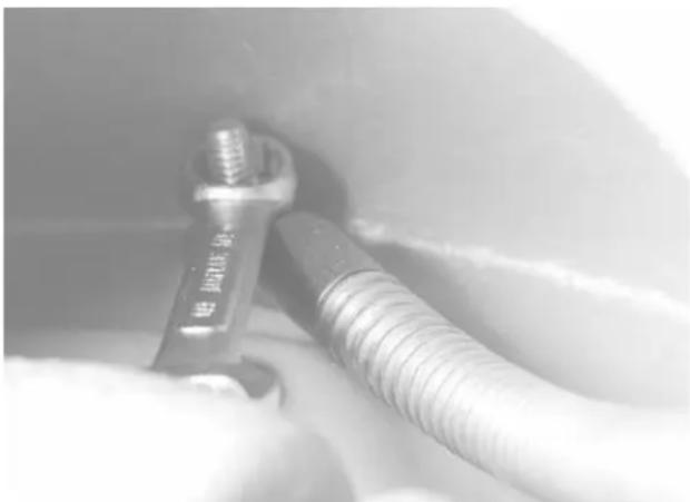
Remove the bolt anchoring the pigtail. It is located on the back of the drum (Figure 14).
natural_image
Close-up of a metallic screw and nut assembly with threaded shaft (no visible text or symbols)Figure 14 – Removing Pigtail Anchoring Bolt
- Remove the pigtail from the guide tube and drum and insert new pigtail into the drum.
- Align hole in pigtail with the hole in the back of the drum. Insert bolt, washers and nut and tighten securely. Push the remainder of the pigtail into drum.
- Push the end of the pigtail through guide tube. Install inner drum and bearing by reversing Steps 4 and 5.
- Place the drum assembly into the machine by following instructions in Step 2 of Drum Assembly Installation section.
Proper Tool Selection
A good rule of thumb is to make the first pass with either a grease cutter or blade cutter that is 2" smaller than the drain size. For additional passes, larger tools may be used. However, tools should generally be at least 1" smaller than the drain size. Use a full size blade on the final pass.
The style of tool is determined by the nature of the job and is left to the discretion of the operator.
Flexible leaders should be used to negotiate bends and traps in lines.
Accessories
⚠ WARNING Only the following RIDGID products have been designed to function with the K-6200 Drain Cleaning Machine. Other accessories suitable for use with other tools may become hazardous when used on the K-6200. To prevent serious injury, use only the accessories listed below.
Catalog No. Description
• 49032 Front Guide Hose Assembly
• 95797 Lifting Hook
• 95792 Swivel Loading Wheel Assembly
• 95802 K-6200 Drum Assy. w/ ^5/8 " Pigtail
• 95807 K-3800 Drum Assy. w/6200 Adapters
• 95822 K-3800 to K-6200 Adapter Kit Only
• 59982 Cable Rust Inhibitor 1 Qt.
• 59987 Cable Rust Inhibitor 1 Gal.
NOTE! See page 5 for listing of cables and tools for the K-6200. Consult a Ridge tool Catalogue for listing of tools and cables to be used with the K-3800 drum.
K-3800 Drum Option
Installing K-3800 Drum
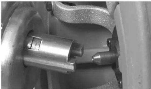
- Insert rear adapter into gear box in back of drum, inserting "O" ring end into drive gear. "O" ring will hold adapter in place while installing drum. (Figure 15)
natural_image
Close-up of mechanical components including a cylindrical shaft and flanged housing (no visible text or symbols)Figure 15 - K-3800 Drum with K-6200 Adapters
-
Place front hex adapter on front nosepiece of guide tube assembly and tighten wing nut.
-
Slide drum assembly into rear adapter on gear box.
- Nest hex head front adapter onto front mounting block.
- Attach AUTOFEED by sliding the assembly onto the cable. Slide assembly onto front support and align with hex adapter. Tighten wing nuts.
Using the K-3800 Drum
- The K-3800 drum should only be used to clean drain lines 2" to 4" in diameter.
WARNING Only 12 " diameter cable is recommended for use in this K-3800 option. Use of smaller diameter cables may result in kinking and breakage.
- Follow the same Operating Instructions previously outlined when cleaning drain. To use the AUTOFEED, Feed knob must be turned until top bearing makes contact with the cable. Turn one full additional turn but do not over-tighten.
natural_image
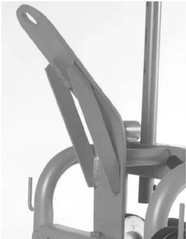
Close-up of a metallic mechanical device with curved arms and a handle (no visible text or symbols)Figure 16 – Lifting Hook
Maintenance Instructions
WARNING
Make sure machine is unplugged from power source before performing maintenance or making any adjustment.
AUTOFEED Assembly
Proper cleaning and lubrication of the AUTOFEED is advised for long, trouble-free operation. After each use, hose out AUTOFEED with water and grease bearings.
Lubrication
Grease all exposed, moving and rotating parts as required. A grease fitting is provided for the drum front and rear bearings.
Cables
Drain drum after every use. Flush drum periodically, remove sediment that can corrode cable.
Cables should be thoroughly flushed with water to prevent damaging effects of drain cleaning compounds. Periodically lubricate cables and couplings with RIDGID Cable Rust Inhibitor.
When not in use, store cables indoors to prevent deterioration by the elements.
Cables should be replaced when they become severely corroded or worn. A worn cable can be identified when outside coils of cable become flat or lose their rigidity.
Machine Storage
⚠ WARNING Motor-driven equipment must be kept in-doors or well covered in rainy weather. Store the machine in a locked area that is out of reach of children and people unfamiliar with drain cleaners. This machine can cause serious injury in the hands of untrained users.
Service and Repair
WARNING

The “Maintenance Instructions” will take care of most of the service needs of this machine. Any problems not addressed by this section should only be handled by an authorized RIDGID service technician.
Tool should be taken to a RIDGID Independent Auth- orized Service Center or returned to the factory. All re pairs made by Ridge service facilities are warranted against defects in material and workmanship.
⚠ WARNING When servicing this machine, only identical replacement parts should be used. Failure to follow these instructions may create a risk of electrical shock or other serious injury.
For information on your nearest RIDGID® Independent Service Center or any service or repair questions:
- Contact your local RIDGID distributor.
- Visit www.RIDGID.com or www.RIDGID.eu to find your local RIDGID contact point.
- Contact Ridge Tool Technical Service Department at rtctechservices@emerson.com or in the U.S. and Canada call (800) 519-3456
Chart 1 Troubleshooting
| PROBLEM POSSIBLE REASONS SOLUTION | ||
| Cable kinking or breaking. | Cable is being forced. | Do Not Force Cable! Let the cutter do the work. |
| Cable used in incorrect pipe diameter. | Use 58 " cables in 3" to 6" lines. Use Trap Leader | |
| Motor switched to reverse. | Use reverse only if cable gets caught in pipe. | |
| Cable exposed to acid. | Clean and oil cables routinely. | |
| Cable worn out. | If cable is worn, replace it. | |
| Drum stops while pedal is depressed. Restarts when pedal is re-depressed. | Hole in pedal or connecting hose. | Replace damaged component. |
| Hole in diaphragm switch. | If no problem found with pedal or hose, replace diaphragm switch. | |
| Drum turns in one direction but not the other. | Faulty reverse switch. | Replace switch. |
| Ground Fault Circuit Interrupter trips when machine is plugged in or when foot pedal is depressed. | -Damaged power cord. | Replace cord set. |
| -short circuit in motor. | Take motor to authorized service center. | |
| Faulty Ground Fault Circuit Interrupter. | Replace cord set that includes a Ground Fault Circuit Interrupter. | |
| Motor turning but drum is not. | Torque limiter slipping because cable is being forced. | Do not force cable. |
| AUTOFEED does not work properly. | AUTOFEED is not routinely cleaned and fills with debris. | -Disassemble AUTOFEED and clean monthly. |
| AUTOFEED is not greased enough. | Apply grease to fittings weekly. | |
| AUTOFEED does not nest properly. | Drum may not be tight onto rear gear box drive. | Nest drum tightly to rear drive lug. |
| Machine wobbles or moves when cleaning a drain. | Kickstand not engaged. | Engage kickstand. |
| Set on level surface. | ||
natural_image
Exterior view of a Ridditi Rollupand electric vehicle (no signage or text on the device itself)natural_image
RIDGE Selimana tool kit with open case, clamps, and textured fabric (no visible text or symbols)natural_image
Two mechanical spring components labeled 1 and 2, showing different assembly states (no text or symbols present)natural_image
Pure mechanical diagram showing a screwdriver inserted into a spring-loaded housing connected to a wall-mounted component (no text or symbols)natural_image
Close-up of a gray metal bicycle handle with a black wheel and attached lever (no text or symbols visible)natural_image
Exterior view of a gray industrial machine with wheels and control panel (no visible text or symbols)natural_image
Four black-and-white pictograms showing different workplace behaviors: running, explosive impact, falling with a device, and using a tool (no text or symbols)natural_image
Close-up of a person's legs and feet wearing boots, with visible tire and mechanical components (no text or symbols)natural_image
Mechanical device with wheels and a handle, shown in black and white (no visible text or symbols)natural_image
Man operating a large industrial machine with tools, no visible text or symbolsnatural_image
Close-up of a mechanical component with metallic surfaces and bolt holes (no text or symbols visible)Figure 10 – Bouchon de vidange du tambour
natural_image
Mechanical device with mounted pump and motor, no visible text or symbolsFigure 11 – Machine en position couchée
natural_image
Close-up of a mechanical assembly showing internal components and mounting holes (no visible text or symbols)natural_image
Close-up of hands operating a mechanical tool inside a cylindrical device labeled 'K-G200', with no visible text or symbols on the tool itself.natural_image
Close-up of a metal screw with threaded shaft, held by gloved hands (no visible text or symbols)natural_image
Close-up of a mechanical assembly with a metallic cylindrical component inserted into a housing (no visible text or symbols)natural_image
Close-up of a metallic mechanical device with curved arms and a handle (no visible text or symbols)Figure 16 – Crochet de levage
Entretien
AVERTISSEMENT
natural_image
Exterior view of a mechanical pressure testing machine (no signage or text visible on the device itself)natural_image
Ridge River basin tool kit with open lid and multiple clamps (no visible text or symbols)natural_image
Diagram of a screwdriver connecting two threaded components to a bracket (no text or symbols)Desconexión
natural_image
Close-up of a gray bicycle lift with a black wheel and attached frame (no text or symbols visible)natural_image
Exterior view of a gray industrial machine with wheels and control panel (no visible text or symbols)natural_image
Close-up of a person's legs and wheel next to an aircraft landing gear (no visible text or symbols)natural_image
Mechanical device with wheels and a motor, mounted on a stand (no visible text or symbols)natural_image
Man operating a mechanical pump cart with tools, no visible text or symbolsnatural_image
Close-up of a mechanical component with a metallic rim and mounting holes (no text or symbols visible)natural_image
Mechanical device with articulated arm and wheels, no visible text or symbolsnatural_image
Close-up of a mechanical assembly with metallic components and bolts (no visible text or symbols)natural_image
Close-up of hands assembling a mechanical component with a tool inside a circular housing (no visible text or symbols)natural_image
Close-up of a metallic wrench and threaded screw component in a mechanical setting (no visible text or symbols)natural_image
Close-up of mechanical components including a metallic cylindrical shaft and flanged housing (no visible text or symbols)Figura 15 – Tambor K-3800 con adaptadores K-6200
natural_image
Close-up of a metallic exercise machine with lever mechanism (no visible text or symbols)RIDGID ^® tools are warranted to be free of defects in workmanship and material.
How long coverage lasts
This warranty lasts for the lifetime of the RIDGID tool. Warranty coverage ends when the product becomes unusable for reasons other than defects in workmanship or material.
How you can get service
To obtain the benefit of this warranty, deliver via prepaid transportation the complete product to RIDGE TOOL COMPANY, Elyria, Ohio, or any authorized RIDGIONDEPENDENT SERVICE CENTER. Pipe wrenches and other hand tools should be returned to the place of purchase.
What we will do to correct problems
Warranted products will be repaired or replaced, at RIDGE TOOL'S option, and returned at no charge; or, if after three attempts to repair or replace during the warranty period the product is still defective, you can elect to receive a full refund of your purchase price.
What is not covered
Failures due to misuse, abuse or normal wear and tear are not covered by this warranty. RIDGE TOOL shall not be responsible for any incidental or consequential damages.
How local law relates to the warranty
Some states do not allow the exclusion or limitation of incidental or consequential damages, so the above limitation or exclusion may not apply to you. This warranty gives you specific rights, and you may also have other rights, which vary, from state to state, province to province, or country to country.
No other express warranty applies
This FULL LIFETIME WARRANTY is the sole and exclusive warranty for RIDGE products. No employee, agent, dealer, or other person is authorized to alter this warranty or make any other warranty on behalf of the RIDGE TOOL COMPANY.

Parts are available online at RIDGIDParts.com

Ridge Tool Company
400 Clark Street
Elyria, Ohio 44035-6001
U.S.A.
Ce qui est couvert


- Drain Cleaning Machine
- WARNING!
- Table of Contents
- General Safety Information
- Specific Safety Information
- Description, Specifications and Standard Equipment
- Machine Assembly
- Special Applications Procedure
- Accessories
- Maintenance
- K-6200
- SAVE THESE INSTRUCTIONS!
- Work Area Safety
- Electrical Safety
- Personal Safety
- Tool Use and Care
- Service
- WARNING
- Drain Cleaner Safety
- Description
- Specifications
- Standard Equipment
- Standard Accessories
- Optional Accessories
- Catalog No. Description
- Instructions For Installing Handles
- Instructions For Installing Cable
- Connecting/Disconnecting 5/8" and 3/4" Drum Machine Cable Couplings
- New style - Plunger pin
- Old style - Rotating pin
- Instructions For Installing Loading Wheel
- Instructions For Installing Lifting Hook
- (Optional Accessory)
- Machine Inspection
- To prevent serious injury, inspect your Drain Cleaning Machine. The following inspection procedures should be performed before each use.
- WARNING Worn or damaged cables can break causing serious injury.
- Machine and Work Area Set-Up
- To prevent serious injury, proper set-up of the machine and work area is required. The following procedures should be followed to set-up machine:
- Operating Instructions
- Always wear eye protection to protect your eyes against dirt and other foreign objects. Wear rubber soled, non-slip shoes.
- Before starting machine, operator's gloved hand must be on the cable.
- Special Procedures
- Main Sewer Or Septic Tank Overrun
- Reverse Operation
- Loading The Machine On Vehicle
- Loading Wheel
- Lifting Hook
- Draining the Drum
- Operating Machine In Reclined Position
- Drum Assembly Removal & Installation
- Drum Removal
- Drum Installation
- Installing Extra Drum (Additional Cable)
- Pigtail Removal and Installation
- Proper Tool Selection
- K-3800 Drum Option
- Installing K-3800 Drum
- Using the K-3800 Drum
- Maintenance Instructions
- AUTOFEED Assembly
- Lubrication
- Cables
- Machine Storage
- Service and Repair
- Entretien
- AVERTISSEMENT
- Desconexión
- How long coverage lasts
- How you can get service
- What we will do to correct problems
- What is not covered
- How local law relates to the warranty
- No other express warranty applies
- Ce qui est couvert
Brand : RIDGID
Model : K6200
Category : Steam cleaner