ATHA5050H - Headphone amplifier AUDIO TECHNICA - Free user manual and instructions
Find the device manual for free ATHA5050H AUDIO TECHNICA in PDF.
User questions about ATHA5050H AUDIO TECHNICA
0 question about this device. Answer the ones you know or ask your own.
Ask a new question about this device
Download the instructions for your Headphone amplifier in PDF format for free! Find your manual ATHA5050H - AUDIO TECHNICA and take your electronic device back in hand. On this page are published all the documents necessary for the use of your device. ATHA5050H by AUDIO TECHNICA.
USER MANUAL ATHA5050H AUDIO TECHNICA
text_image
audio-technica — Headphone Amplifier AT-HAS0001 Input Headphones Min • Max VU Range取扱説明書
ヘッド ホンアンプ
Instruction booklet
Headphone Amplifi er
使用说明书
立体声耳机放大器
使用說明書
耳機放大器
目次
安全上の注意 3
ヘッドホンアンプについて 3
電源ケーブルについて 3
使用上の注意 4
ご使用の前に 4
各部の名称と機能 5
前面(フロントパネル) 5
背面(リアパネル) 6
接続のしかた 7
ヘッドホン出力端子の使いかた 8
VU メーターの使いかた 9
text_image
Headphone Amplifier AT-HA5050H 120 Ω 82 Ω 33 Ω 0.1 Ω OUTPUT MPEDANCE CED headphone 1 2 3 4Part names and functions 17
Front panel 17
Rear panel 18
Connections 19
How to use headphone output terminals · · 20
How to use a VU meter 21
How to use the control panel 22
Block diagram 23
Dimensions 23
Specifications 24
Thank you for purchasing this Audio-Technica product. Be sure to read this manual before using this product. Also, store this manual together with the warranty in an easily accessible location.
Dedicated driver software is required in order to use this headphone amplifier. Please download the latest driver software from the website address listed under
"AT-HA5050H Product Dedicated Address" on page 16 of these operating instructions.
*Only for Windows users.
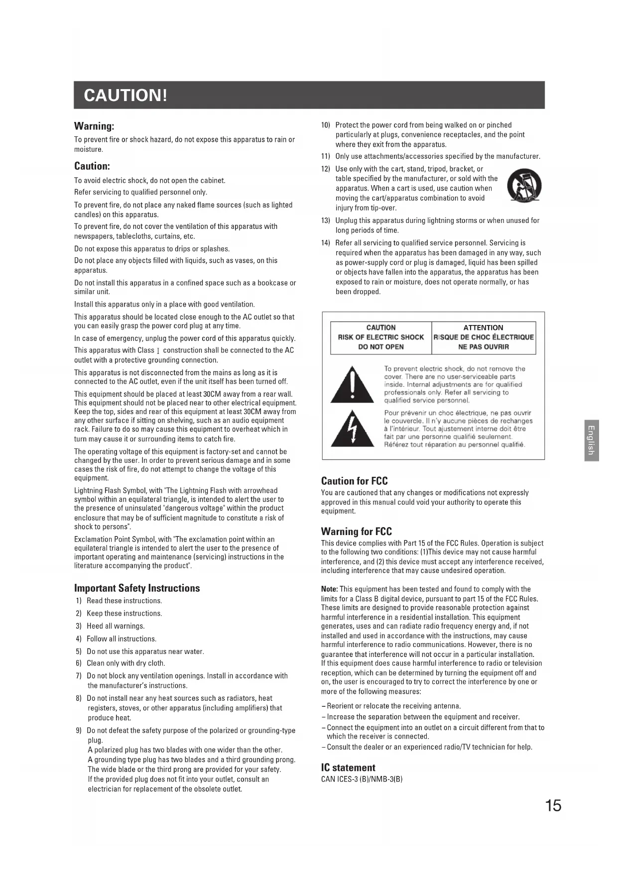
CAUTION!
Warning:
To prevent fire or shock hazard, do not expose this apparatus to rain or moisture.
Caution:
To avoid electric shock, do not open the cabinet.
Refer servicing to qualified personnel only.
To prevent fire, do not place any naked flame sources (such as lighted candles) on this apparatus.
To prevent fire, do not cover the ventilation of this apparatus with newspapers, tablecloths, curtains, etc.
Do not expose this apparatus to drips or splashes.
Do not place any objects filled with liquids, such as vases, on this apparatus.
Do not install this apparatus in a confined space such as a bookcase or similar unit.
Install this apparatus only in a place with good ventilation.
This apparatus should be located close enough to the AC outlet so that you can easily grasp the power cord plug at any time.
In case of emergency, unplug the power cord of this apparatus quickly.
This apparatus with Class I construction shall be connected to the AC outlet with a protective grounding connection.
This apparatus is not disconnected from the mains as long as it is connected to the AC outlet, even if the unit itself has been turned off.
This equipment should be placed at least 30CM away from a rear wall. This equipment should not be placed near to other electrical equipment. Keep the top, sides and rear of this equipment at least 30CM away from any other surface if sitting on shelving, such as an audio equipment rack. Failure to do so may cause this equipment to overheat which in turn may cause it or surrounding items to catch fire.
The operating voltage of this equipment is factory-set and cannot be changed by the user. In order to prevent serious damage and in some cases the risk of fire, do not attempt to change the voltage of this equipment.
Lightning Flash Symbol, with "The Lightning Flash with arrowhead symbol within an equilateral triangle, is intended to alert the user to the presence of uninsulated "dangerous voltage" within the product enclosure that may be of sufficient magnitude to constitute a risk of shock to persons".
Exclamation Point Symbol, with "The exclamation point within an equilateral triangle is intended to alert the user to the presence of important operating and maintenance (servicing) instructions in the literature accompanying the product".
Important Safety Instructions
1) Read these instructions.
2) Keep these instructions.
3) Heed all warnings.
4) Follow all instructions.
5) Do not use this apparatus near water.
6) Clean only with dry cloth.
7) Do not block any ventilation openings. Install in accordance with the manufacturer's instructions.
8) Do not install near any heat sources such as radiators, heat registers, stoves, or other apparatus (including amplifiers) that produce heat.
9) Do not defeat the safety purpose of the polarized or grounding-type plug.
A polarized plug has two blades with one wider than the other. A grounding type plug has two blades and a third grounding prong. The wide blade or the third prong are provided for your safety. If the provided plug does not fit into your outlet, consult an electrician for replacement of the obsolete outlet.
10) Protect the power cord from being walked on or pinched particularly at plugs, convenience receptacles, and the point where they exit from the apparatus.
11) Only use attachments/accessories specified by the manufacturer.
12) Use only with the cart, stand, tripod, bracket, or table specified by the manufacturer, or sold with the apparatus. When a cart is used, use caution when moving the cart/apparatus combination to avoid injury from tip-over.
13) Unplug this apparatus during lightning storms or when unused for long periods of time.
14) Refer all servicing to qualified service personnel. Servicing is required when the apparatus has been damaged in any way, such as power-supply cord or plug is damaged, liquid has been spilled or objects have fallen into the apparatus, the apparatus has been exposed to rain or moisture, does not operate normally, or has been dropped.
CAUTION RISK OF ELECTRIC SHOCK DO NOT OPEN
ATTENTION RISQUE DE CHOC ÉLECTRIQUE NE PAS OUVRIR

To prevent electric shock, do not remove the cover. There are no user-serviceable parts inside. Internal adjustments are for qualified professionals only. Refer all servicing to qualified service personnel.

You are cautioned that any changes or modifications not expressly approved in this manual could void your authority to operate this equipment.
Warning for FCC
This device complies with Part 15 of the FCC Rules. Operation is subject to the following two conditions: (1) This device may not cause harmful interference, and (2) this device must accept any interference received, including interference that may cause undesired operation.
Note: This equipment has been tested and found to comply with the limits for a Class B digital device, pursuant to part 15 of the FCC Rules. These limits are designed to provide reasonable protection against harmful interference in a residential installation. This equipment generates, uses and can radiate radio frequency energy and, if not installed and used in accordance with the instructions, may cause harmful interference to radio communications. However, there is no guarantee that interference will not occur in a particular installation. If this equipment does cause harmful interference to radio or television reception, which can be determined by turning the equipment off and on, the user is encouraged to try to correct the interference by one or more of the following measures:
– Reorient or relocate the receiving antenna.
– Increase the separation between the equipment and receiver.
- Connect the equipment into an outlet on a circuit different from that to which the receiver is connected.
- Consult the dealer or an experienced radio/TV technician for help.
IC statement
CAN ICES-3 (B)/NMB-3(B)
Cautions
● Headphone output terminals of the product are for the use of stereo headphones only. Never connect devices other than stereo headphones.
● To connect 3.5 mm stereo headphone mini plug, use an appropriate conversion plug adapter (sold separately). Please note that, depending on the shape of the conversion plug, it may be difficult to remove it from the jack.
- The contact pressure of the jack of this product is designed to be a little stronger in order to improve the sound quality. It may be difficult to remove some plugs (especially small plugs that are had to grip) from the jack.
- When turn on/off the power or connect headphones to this product, make sure to set volume to the minimum level. Sudden loud sound may have bad effects on hearing. Also, it may cause failure of the headphone.
- Please buy a cable suitable for the device to be connected.
● Fully insert the plug of the connecting cable.
- Stop playback device when plugging or unplugging cables.
● A vacuum tube used in this product can cause it to become hot, but this is not a malfunction.
- Keep this product at least 1 m from inverter-type fluorescent lights, LED lamps, mobile telephones, Wi-Fi and other wireless devices. If you use this product near those devices, noise may be caused.
- A vacuum tube is used in this product. To get sufficient sound quality, make sure to turn on the power and age it before using this product.
• Before using it for the first time: at least 3 days
· Before each use: at least 15 minutes
Before use
Download the dedicated driver software from the AT-HA5050H product website and install it on your computer before connecting this product to a PC for the first time. Please always install the "dedicated driver software."
If you connect the product to the computer before installing the driver, it may not work properly.
*Only for Windows users.
■ AT-HA5050H Product Dedicated Address
You can download the drivers from the product website below. http://www.audio-technica.co.jp/atj/at_ha5050h.html
- For details on how to install the dedicated driver software, see the separate "Installation and Setup Manual" also on the website.
- This product may not operate correctly due to the hardware or software configuration of your computer, even if the computer fulfills the "compatible operating environment" conditions which is indicated in Specifications.
- Since audio data output from a computer is processed in asynchronous mode using the clock of this product, jitter caused during transmission of data can be reduced.
● The files that you can download from the product website are as follows.
Windows Installation manual, setup manual
Mac OS Setup manual (No installation required for the dedicated driver software)
The AT-HA5050H product website will be updated with the latest installation and setup information. Please check back frequently for the latest information.
Part names and functions
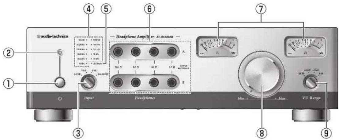
Front panel
text_image
audio-technica 4 5 6 7 Headphone Amplifier AT-MA350H A 100 Ω 82 Ω 33 Ω 0.1 Ω OUTPUT REFERENCE B Input Headphones Min Max VU Range L VU R VU -20 dB -12 dB -30 dB -5 dB ① ② ③ ④ ⑤ ⑥ ⑧ ⑨① Power switch
Push-type switch to turn the power on/off.
The power is turned on by pressing the switch. The power is turned off by pressing the switch again.
② Power indicator
When the power is turned on, the indicator lights orange for approximately 60 seconds (standby mode). After that, the indicator lights green (operation mode). If the orange indicator does not turn green, refer to the instructions for use on page 16.
③ Input selector switch
Changes input signals (coaxial digital input (S/PDIF), USB input (USB), line input (LINE), XLR input (BALANCED)).
④ Type of digital input and sampling frequency indicator
Displays the type of digital input and sampling frequency.*
* During coaxial digital (S/PDIF) input, sampling frequency may not be shown correctly, depending on the player to be connected.
⑤ Bit depth indicator
Displays the bit width during USB input.
| When USB is not connected | : The light is turned off. |
| When USB is connected (not played) | : blue |
| During playback of 16 bit | : blue |
| During playback of 24 bit/32 bit | : pink |
Displays the bit width during coaxial digital (S/PDIF) input.
| When coaxial digital (S/PDF)is not connected | : The light is turned off. |
| During playback of 16 bit | : blue |
| During playback of 24 bit | : pink |
⑥ Headphone output jacks
Headphone terminal for 6.3 mm standard stereo jack. When used under the same conditions, two headphones can be used at the same time. The output impedance (0.1 Ω, 32Ω, 82Ω, and 120 Ω) of an amplifier is displayed. This is not headphone impedance.
⑦ VU meter
Indicates the strength of headphone output.
* For more information, refer to "How to use a VU meter" (page 21).
⑧ Volume
Used to adjust the headphone volume. To decrease or increase the volume level, turn the button toward MIN or MAX, respectively.
* When two headphones are connected to headphone terminals A and B, both are adjusted at the same time.
⑨ VU meter range selector switch
Optimizes meter display based on the headphone sensitivity.
* For more information, refer to "How to use a VU meter" (page 21).
Part names and functions
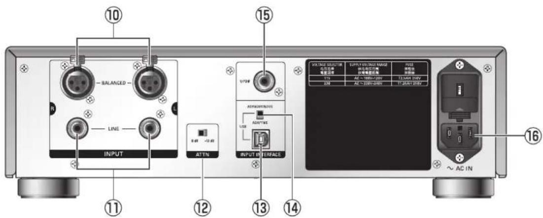
Rear panel
text_image
10 BALANCED LINE INPUT ATTN 9.48 -12.48 15 S7P# AEM/AC/REFIN/UE USS INPUT IN INTERFACE VOLTAGE SELECTOR 供电连接 电源连接 113 AC ~ 160V~28V 12.5kW 316V 3.20 AC ~ 200V~28V 12.5kW 316V VOLTAGE SELECTOR 供电连接 电源连接 电源连接 113 AC ~ 160V~28V 12.5kW 316V 3.20 AC ~ 200V~28V 12.5kW 316V ~ AC IN 16⑩ XLR input terminals (BALANCED)
Use an XLR cable (optional) to connect to a CD player or other device equipped with XLR output terminals.
⑪ Line input terminal (LINE)
Use an audio cable (optional) to connect to a CD player or amplifier line output terminals. Jack is pin-shaped.
⑫ Input attenuator switch (ATTN)
This is a -12 dB input attenuator. Use this when a large signal level is input.
⑬ USB input terminal (USB)
Use a USB cable (optional) to connect to a computer.
⑭ USB connection mode selector switch
Switches between asynchronous mode and adaptive mode. Make selection based on environment of computer to be connected.
⑮ Digital coaxial input terminal (S/PDIF)
When digital input is performed, use a coaxial digital cable (optional) to connect to the device equipped with the digital output.
⑯ Power cable inlet (\~ AC IN)
Connect the power cable.
Connections
* Please also read instruction manual of audio device.
* Be sure to turn off the power to each device before connecting.
* The USB terminal of this product is self-powered (does not require power from a computer).
- With reference to "Connection example", connect a computer and other devices to be used.
- Insert the power cable into the inlet on this product and 100V AC outlet.
- Turn on the connected devices.
- Turn on this product. Wait until the power LED indicator turns from orange to green (about 60 seconds).
- Select the device for playback using the input selector switch.
- After turning down the volume on this product, connect the headphone to the headphone output terminal. For more information on headphone impedance and headphone terminals to be used, refer to "How to use headphone output terminals."
* If a headphone is inserted or extracted with loud signal input to this product, the power indicator will turn orange temporarily and the audio will be muted. This is not a failure; it is caused by the activation of the amplifier protection circuit. A short time later (about 60 seconds), the volume will be restored to the original volume level.
* If your headphone has a 3.5 mm stereo mini plug, you will need to use a conversion plug adapter. Please note that it may be difficult to pull some plug adapters out of the jack. See "Cautions" on page 16.
-
Play the playback device and adjust to the desired volume level using the Volume knob on this product.
-
Adjust the volume and the VU meter range selector switch so that the VU meter's pointer is within the display range. For more information, refer to "How to use a VU meter" (page 21).
* If you use the meter until the pointer goes off the scale, it may cause failure of the meter.
Connection example

text_image
DVD player CD player Personal computer Audio cable (optional) XLR cable (optional) Coaxial digital cable (optional) USB cable 1.0 m (optional) INPUT AC IN Headphone Amplifier antenna 6.3 mm stereo plugx2 headphonex2 * When used under the same conditions, two headphones lone to headphone output A, one to output B) can be used at the same time.How to use headphone output terminals
text_image
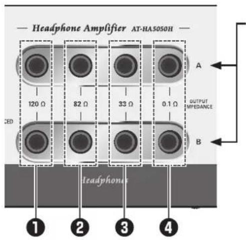
Headphone Amplifier AT-HA5050H 120 Ω 82 Ω 33 Ω 0.1 Ω CED OUTPUT MPEDANCE A B 1 2 3 4 HeadphoneThis product has two headphone outputs.
Connect one headphone to output A, one to output B.
Select and use the output terminal to your liking with reference to the following examples.
Examples of use
To use 16 to 64 ohms impedance headphones:
Use the output terminal with ④ 0.1 ohms output impedance.
When you use the output terminal with low impedance, high-resolution, powerful sound will be produced.
When you use the output terminal with high impedance, rich sound in the low-mids will be produced.
To use 100 ohms or higher impedance headphones:
Use the output terminal with the output impedance of your choice.
When you use the output terminal with low impedance, high-resolution, tight sound will be produced.
When you use the output terminal with high impedance, rich sound in the low-mids will be produced.
To use balanced armature-based earbud headphones:
When balanced armature-based earbud headphones for a single unit are used, use any output terminal of your choice.
When balanced armature-based earbud headphones for two or more units are used, use the output terminal with ④ 0.1 ohms output impedance.
When an output terminal with high impedance is used, you may not get good frequency characteristics.
To use different impedance headphones and make volume levels uniform: (Connect two headphones to outputs A and B.)
Connect the higher impedance headphones to the output terminal with ④ 0.1 ohms output impedance.
Select the output terminal with ① 120 ohms, ② 82 ohms, or ③ 33 ohms output impedance, so that the volume level of the two headphones becomes the same. Since different headphones have different output sound pressure levels, you may not get the same volume level.
How to use a VU meter
The unit of measurement for a VU meter on this device is decibel (dB).
To check the output power, refer to "How to read levels against the range switch" and the conversion table below.
* If you use the meter until the pointer goes off the scale, it may cause failure of the meter.
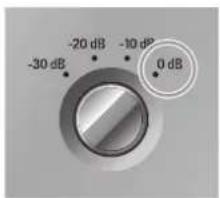
When set to 0 dB
text_image
-20 dB -10 dB -30 dB 0 dB-10 dB Position
16 ohms 6.25 mW
32 ohms 3.13 mW
64 ohms 1.56 mW
150 ohms 0.67 mW
300 ohms 0.33 mW
600 ohms 0.17 mW
0 dB Position
16 ohms 62.50 mW
32 ohms 31.25 mW
64 ohms 15.63 mW
150 ohms 6.67 mW
300 ohms 3.33 mW
600 ohms 1.67 mW
3 dB Position
16 ohms 124.70 mW
32 ohms 62.35 mW
64 ohms 31.18 mW
150 ohms 13.30 mW
300 ohms 6.65 mW
600 ohms 3.33 mW
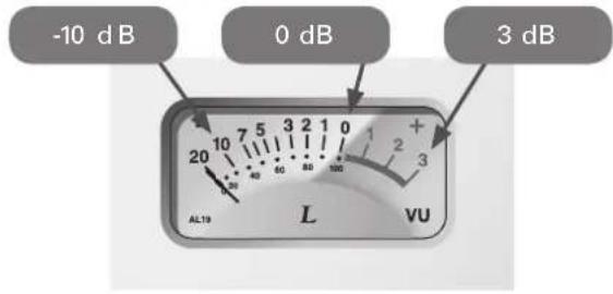
text_image
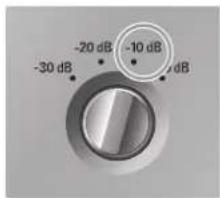
-10 dB 0 dB 3 dB 20 10 7 5 3 2 1 0 + - 2 3 L vU AL19When set to -10 dB
text_image
-20 dB -10 dB -30 dB-20 dB Position
16 ohms 0.63 mW
32 ohms 0.31 mW
64 ohms 0.16 mW
150 ohms 0.07 mW
300 ohms 0.03 mW
600 ohms 0.02 mW
-10 dB Position
16 ohms 6.25 mW
32 ohms 3.13 mW
64 ohms 1.56 mW
150 ohms 0.67 mW
300 ohms 0.33 mW
600 ohms 0.17 mW
-7 dB Position
16 ohms 12.47 mW
32 ohms 6.24 mW
64 ohms 3.12 mW
150 ohms 1.33 mW
300 ohms 0.67 mW
600 ohms 0.33 mW
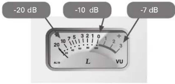
text_image
-20 dB -10 dB -7 dB AL18 L vUWhen set to -20 dB
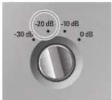
text_image
-20 dB -30 dB -10 dB 0 dB-30 dB Position
16 ohms 0.06 mW
32 ohms 0.03 mW
64 ohms 0.02 mW
150 ohms 0.01 mW
300 ohms 0.00 mW
600 ohms 0.00 mW
-20 dB Position
16 ohms 0.63 mW
32 ohms 0.31 mW
64 ohms 0.16 mW
150 ohms 0.07 mW
300 ohms 0.03 mW
600 ohms 0.02 mW
-17 dB Position
16 ohms 1.25 mW
32 ohms 0.62 mW
64 ohms 0.31 mW
150 ohms 0.13 mW
300 ohms 0.07 mW
600 ohms 0.03 mW

text_image
-30 dB -20 dB -17 dB AL19 L vuWhen set to -30 dB
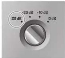
text_image
-30 dB -20 dB -10 dB 0 dB-40 dB Position
16 ohms 0.01 mW
32 ohms 0.00 mW
64 ohms 0.00 mW
150 ohms 0.00 mW
300 ohms 0.00 mW
600 ohms 0.00 mW
-30 dB Position
16 ohms 0.06 mW
32 ohms 0.03 mW
64 ohms 0.02 mW
150 ohms 0.01 mW
300 ohms 0.00 mW
600 ohms 0.00 mW
-27 dB Position
16 ohms 0.12 mW
32 ohms 0.06 mW
64 ohms 0.03 mW
150 ohms 0.01 mW
300 ohms 0.01 mW
600 ohms 0.00 mW
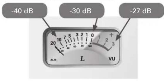
text_image
-40 dB -30 dB -27 dB AL19 L vuHow to use the control panel
When the dedicated driver software is installed, the control panel is installed simultaneously.
* Compatible with Windows 7, Windows 8, and Windows 8.1.
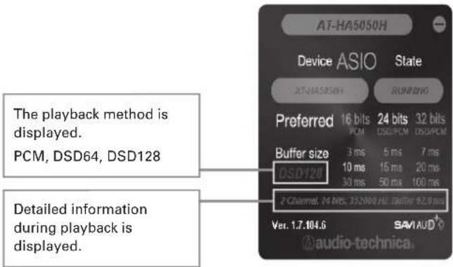
text_image
AT-HA5050H Device ASIO State AT-HA5050H RUNNING Preferred 16 bits 24 bits 32 bits PCM DSD64 DSD128 Buffer size 3 ms 5 ms 7 ms 10 ms 15 ms 20 ms 30 ms 50 ms 100 ms DSD128 2 Channel: 24 Bits. 352000 Hz. Battery: 92.9 ms Ver. 1.7.104.6 SAVAUD® audio-technica.To play DSD data in DoP mode: Select 24 bit or 32 bit.
When WASAPI mode is used, change the sampling frequency and the number of bits using player software.
Block diagram
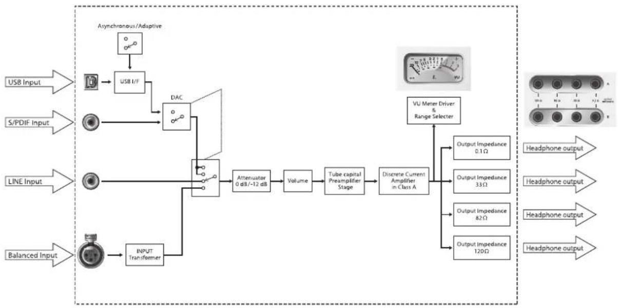
flowchart
graph LR
    A["USB Input"] --> B["USB I/F"]
    C["S/PDIF Input"] --> D["DAC"]
    E["LINE Input"] --> F["Attenuator 0 dB/-12 dB"]
    G["Balanced Input"] --> H["INPUT Transformer"]
    B --> D
    D --> F
    F --> G
    G --> H
    H --> I["Volume"]
    I --> J["Tube capital Preamplifier Stage"]
    J --> K["Discrete Current Amplifier in Class A"]
    K --> L["VU Meter Driver & Range Selector"]
    L --> M["Output Impedance 0.1Ω"]
    L --> N["Output Impedance 33Ω"]
    L --> O["Output Impedance 82Ω"]
    L --> P["Output Impedance 120Ω"]
    style A fill:#f9f,stroke:#333
    style C fill:#f9f,stroke:#333
    style E fill:#f9f,stroke:#333
    style G fill:#f9f,stroke:#333
    style L fill:#ccf,stroke:#333
    style M fill:#cfc,stroke:#333
    style N fill:#cfc,stroke:#333
    style O fill:#cfc,stroke:#333
    style P fill:#cfc,stroke:#333
Dimensions
(unit: mm)
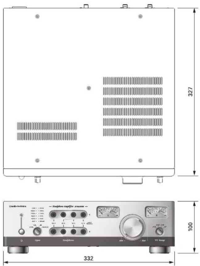
text_image
327 100 332Specifications
| Computer requirements | A computer with a USB 2.0 portCPU Intel Core 2 CPU 2.2GHz above or equivalent AMD CPURAM 32bit OS 2GB or more, 64bit OS 4GB or more | |
| Compatible OS | Windows 7Windows 8Windows8.1Mac OS X10.9 | |
| Type | Preamplifier stage: vacuum circuit Power amplifier stage: Class A bipolar transistor amplifier | |
| Compatible headphone impedance 16 ohms | ~ 600 ohms | |
| Instantaneous maximum output level | 2,000 mW + 2,000 mW (16 ohms load) | |
| 1,000 mW + 1,000 mW (32 ohms load) | ||
| 500 mW + 500 mW (64 ohms load) | ||
| 62 mW + 62 mW (600 ohms load) | ||
| Rated output (20 Hz to 20 kHz) | 125 mW + 125 mW (16 ohms load) | |
| 62 mW + 62 mW (32 ohms load) | ||
| 31 mW + 31 mW (64 ohms load) | ||
| 3.3 mW + 3.3 mW (600 ohms load) | ||
| Frequency response | Line input 5 Hz | ~ 200 kHz (0, -1 dB at 32 ohms 10 mW output) |
| XLR input 5 Hz | ~ 200 kHz (+0.5, -2 dB at 32 ohms 10 mW output) | |
| Total harmonic distortion 0.08% or less (20 Hz) | ~ 20 kHz at 32 ohms 10 mW output) | |
| Gain | Line input 14 dB | |
| XLR input 13.5 dB | ||
| SN ratio 104 dB (A Weighted) | ||
| Separation between channels 70 dB (1 kHz at 32 ohms) | ||
| Input terminals | Analog | Line input (pin jack) ×2 |
| XLR connector ×2 | ||
| Digital | USB (Type B) ×1Asynchronous modeDSD128 (5.6448 MHz), DSD64 (2.8224 MHz): 24 bit ~ 32 bitPCM 384 kHz, 352.8 kHz, 192 kHz, 176.4 kHz, 96 kHz, 88.2 kHz, 48 kHz, 44.1 kHz,32 kHz: 16 bit ~ 32 bitAdaptive modeDSD incompatiblePCM 192 kHz, 176.4 kHz, 96 kHz, 88.2 kHz, 48 kHz, 44.1 kHz, 32 kHz: 16 bit ~ 32 bit | |
| Digital coaxial (S/PDIF) × 1PCM 192 kHz, 176.4 kHz, 96 kHz, 88.2 kHz, 48 kHz, 44.1 kHz, 32 kHz: 16 bit ~ 24 bit | ||
| Output terminals | Headphone output6.3 mm standard stereo jack (output impedance 0.1 ohms) ×26.3 mm standard stereo jack (output impedance 33 ohms) ×26.3 mm standard stereo jack (output impedance 82 ohms) ×26.3 mm standard stereo jack (output impedance 120 ohms) ×2 | |
| DA converter | Frequency response 5 Hz | ~ 100 kHz (0, -1.5 dB) |
| Total harmonic distortion | 0.0006% or less (20 ~ 20 kHz) | |
| SN ratio 113 dB (A Weighted, 1 Vrms output) | ||
| Separation between channels | 110 dB (20 Hz ~ 20 kHz) | |
| Input attenuator -12 dB | ||
| VU meter Range | 0 dB, -10 dB, -20 dB, -30 dB | |
| Power supply | AC220 - 240 V 50/60 Hz, AC120 V 50 Hz (USA/Canada) | |
| Power consumption | Max 53 W | |
| Dimensions | H100 x W332 x D327 mm (excluding protruding parts) | |
| Weight | Approx. 11.0 kg | |
| Accessories | Power cable | |
USB compatibility list
(unit: bit)
| HA5050H Asynchronous PCM384 / DSD128 Windows 7 Windows 8 / 8.1 | ||||
| ASIO | PCM | 32 kHz, 44.1 kHz, 48 kHz88.2 kHz, 96 kHz, 176.4 kHz192 kHz, 352.8 kHz, 384 kHz | ○ 16-32 | ○ 16-32 |
| DSD | DoP64176.4 kHz | ○ 24-32 | ○ 24-32 | |
| DoP128352.8 kHz | ○ 24-32 | ○ 24-32 | ||
| Native6488.2 kHz | ○ 32 | ○ 32 | ||
| Native128176.4 kHz | Incompatible*1 Incompatible*1 | |||
| WASAPI | PCM | 32 kHz, 44.1 kHz, 48 kHz88.2 kHz, 96 kHz, 176.4 kHz192 kHz, 352.8 kHz, 384 kHz | ○ 16-32 | ○ 16-32 |
| DSD | DoP64176.4 kHz | ○ 24-32 | ○ 2 4-32 | |
| DoP128352.8 kHz | ○ 24-32 | ○ 24-32 | ||
| Native6488.2 kHz | Incompatible Incompatible | |||
| Native128176.4 kHz | Incompatible Incompatible | |||
| Direct Sound | PCM | 32 kHz, 44.1 kHz, 48 kHz88.2 kHz, 96 kHz, 176.4 kHz192 kHz | ○ 16-32 | ○ 16-32 |
| DSD | Incompatible Incompatible Incompatible | |||
| HA5050H Adaptive PCM192 Windows 7 Windows 8 / 8.1 | ||||
| ASIO | PCM | 32 kHz, 44.1 kHz, 48 kHz88.2 kHz, 96 kHz, 176.4 kHz192 kHz | ○ 16-32 | ○ 16-32 |
| DSD | DoP64176.4 kHz | Incompatible Incompatible | ||
| DoP128352.8 kHz | Incompatible Incompatible | |||
| Native6488.2 kHz | Incompatible*3 Incompatible*3 | |||
| Native128176.4 kHz | Incompatible*3 Incompatible*3 | |||
| WASAPI | PCM | 32 kHz, 44.1 kHz, 48 kHz88.2 kHz, 96 kHz, 176.4 kHz192 kHz | ○ 16-32 | ○ 16-32 |
| DSD | DoP64176.4 kHz | Incompatible Incompatible | ||
| DoP128352.8 kHz | Incompatible Inочный | |||
| Native6488.2 kHz | Incompatible Incompatible | |||
| Native128176.4 kHz | Incompatible Incompatible | |||
| Direct Sound | PCM | 32 kHz, 44.1 kHz, 48 kHz88.2 kHz, 96 kHz, 176.4 kHz192 kHz | ○ 16-32 | ○ 16-32 |
| DSD | Incompatible Incompatible Incompatible | |||
| HA5050H Asynchronous PCM384 / DSD128 MAC OS | ||
| PCM | 32 kHz, 44.1 kHz, 48 kHz88.2 kHz, 96 kHz, 176.4 kHz192 kHz, 352.8 kHz, 384 kHz | ○ 16-32 |
| DSD | DoP64176.4 kHz | ○ 24-32 *2 |
| DoP128352.8 kHz | ○ 24-32 *2 | |
| Native6488.2 kHz | Incompatible | |
| Native128176.4 kHz | Incompatible | |
| HA5050H Adaptive PCM192 MAC OS | ||
| PCM | 32 kHz, 44.1 kHz, 48 kHz88.2 kHz, 96 kHz, 176.4 kHz192 kHz | ○ 16-32 |
| DSD | DoP64176.4 kHz | Incompatible |
| DoP128352.8 kHz | Incompatible | |
| Native6488.2 kHz | Incompatible | |
| Native128176.4 kHz | Incompatible | |
* 1 If you play accidentally, a loud distorted sound will be emitted.
* 2 When 16 bit is selected, playback will start without any sound being heard.
* 3 Playback will start without any sound being heard.
Avertissement:
Disposal of Old Electrical & Electronic Equipment (Applicable in European countries with separate collection systems)
This symbol on the product or on its packaging indicates that this product shall not be treated as household waste. Instead it shall be handed over to the applicable collection point for the recycling of electrical and electronic equipment. By ensuring this product is disposed of correctly, you will help prevent potential negative consequences for the environment and human health, which could otherwise be caused by inappropriate waste handling of this product. The recycling of materials will help to conserve natural resources. For more detailed information about recycling of this product, please contact your local city office, your household waste disposal service or the shop where you purchased the product.
Deutsch

Audio-Technica Limited
Technica House, Unit 5, Millennium Way, Leeds LS11 5AL, United Kingdom
Manufactured by / fabriqué par / hergestellt durch / Prodotto da / fabricado por / fabricado por / vervaardigd door / Произведено ot / Proizvođač / Výrobce / produceret af / valmistatud / Valmistaja / Katwokeuččetai omó / Gyártó / mhonaraigh / ražojis / Gamintojas / manifatturat minn / wyprodukowane przez / Produs de / Výrobca / Proizvajalec / tillverkad av
Audio-Technica Corp.
2-46-1 Nishi-naruse, Machida, Tokyo 194-8666, Japan
目录
安全及注意事项 30
注意事项 30
使用前 30
部件名称和功能 31
前面板 31
后面板 32
连接 33
如何使用耳机输出端子 34
如何使用音量电平表 35
如何使用控制面板 36
方框图 37
尺寸 37
技术指标 38
USB 兼容性列表 39
text_image
audio-technica Headphone Amplifier AT-HANCHOI Input Headphones Min Max VU Range 1 2 3 4 5 6 7 8 9① 電源開關
開啟 / 關閉電源的按壓式開關。
This explanation is a guidance concerned with the environmental laws and regulations of the People's Republic of China. The printed information as well as the list of contained materials conform with the standard values established by the related laws and regulations of the People's Republic of China, and does not apply to other Restrictions of Hazardous Substances including Europe's RoHS directive.
Deutsch
Audio-Technica Corp. (Headquarters)
2-46-1 Nishi-naruse, Machida, Tokyo 194-8666, Japan
Audio-Technica Limited (Importer for Europe)
Unit 5, Millennium Way, Leeds LS11 5 AL, United Kingdom
Audio-Technica U.S., Inc.
1221 Commerce Drive, Stow, Ohio 44224, USA
©2014-2015 Audio-Technica Corp.
中国大陆客户联系资料
代理商:广州市德讯贸易有限公司