Variant S2520R - Sauna HARVIA - Free user manual and instructions
Find the device manual for free Variant S2520R HARVIA in PDF.



| Brand | HARVIA |
| Model | Variant S2520R |
| Category | Sauna |
| Height | 2030 mm (adjustable feet 20-40 mm) |
| Minimum room height | 2150 mm |
| Supply voltage | 230/240 V single-phase |
| Bulb | Type E14, 25-40 W (max. 40 W) |
| Power cable | 2 x 1.5 mm², min. thermal resistance 170 °C |
| Heating type | Dry sauna or steam |
| Lighting | Integrated, separate switch outside |
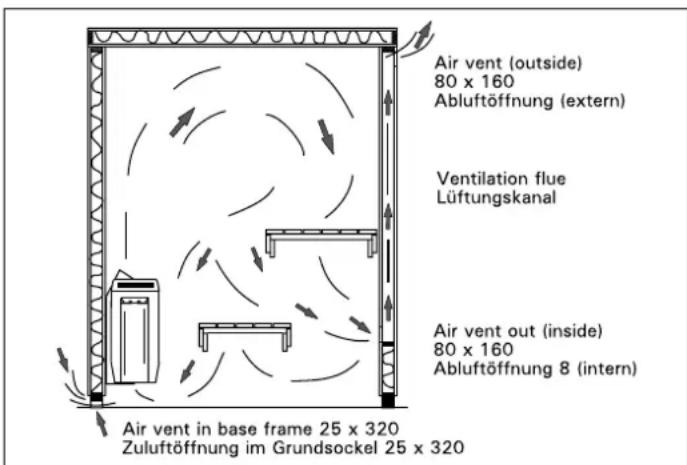
| Ventilation | Air vents included |
| Material | Natural wood |
| Assembly | Kit with screws and nails provided |
| Required tools | Hammer, drill, screwdriver, saw, tape measure, level, sandpaper |
| Electrical installation | By a qualified electrician |
| Maintenance | Use sandpaper, protective coating for the exterior |
| Safety | Do not use products inside, heat empty after steam use |
| Door | Glass, adjustable |
Frequently Asked Questions - Variant S2520R HARVIA
User questions about Variant S2520R HARVIA
0 question about this device. Answer the ones you know or ask your own.
Ask a new question about this device
Download the instructions for your Sauna in PDF format for free! Find your manual Variant S2520R - HARVIA and take your electronic device back in hand. On this page are published all the documents necessary for the use of your device. Variant S2520R by HARVIA.
USER MANUAL Variant S2520R HARVIA
EN Assembly Instructions for Saunas
Kuva 5. Bild 5.
Kuva 6. Bild 6.
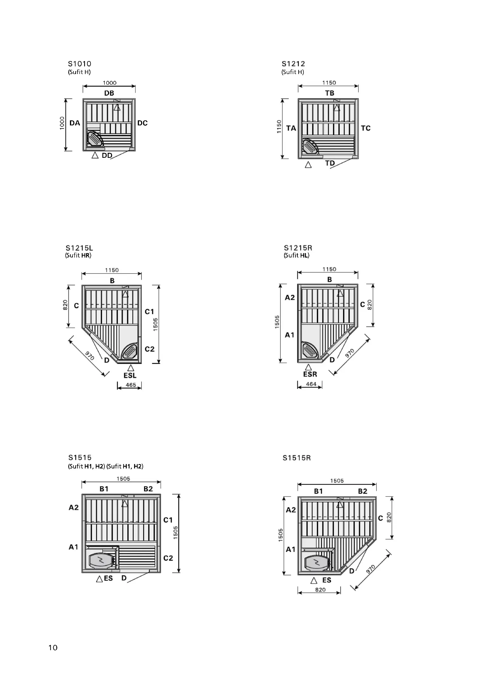
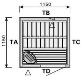
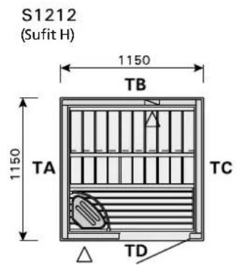
S1212
(Katto/Tak H)
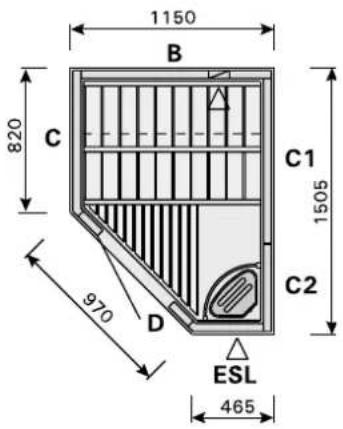
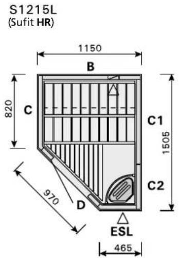
S1215L
(Katto/Tak HR)
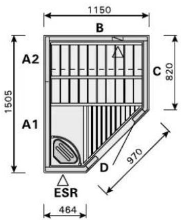
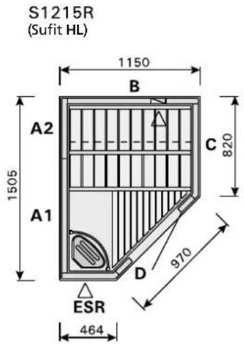
S1215R
(Katto/Tak HL)
S1515
(Katto/Tak H1, H2) (Katto/Tak H1, H2)
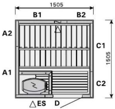
S1515R
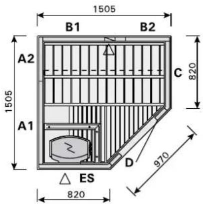
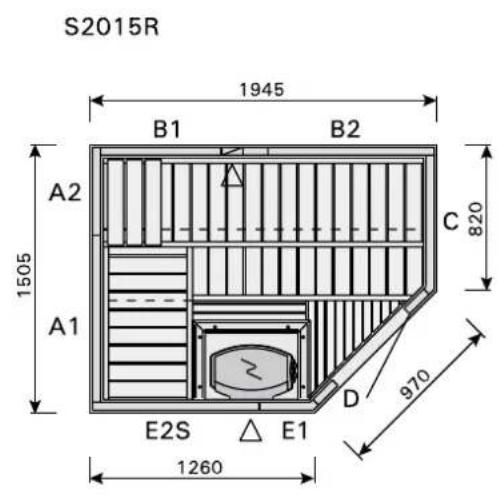
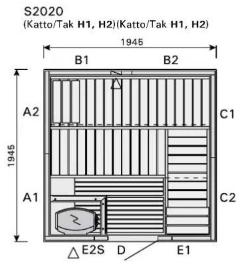
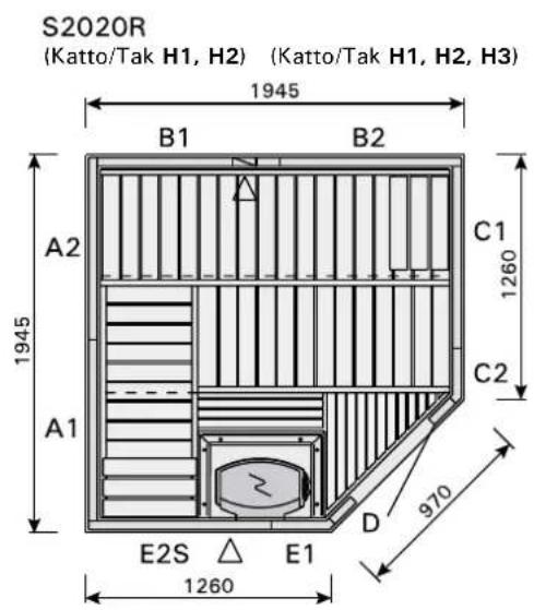
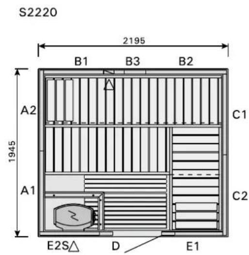
S2220R
(Katto/Tak H1, H2, H3) (Katto/Tak H1, H2, H3)
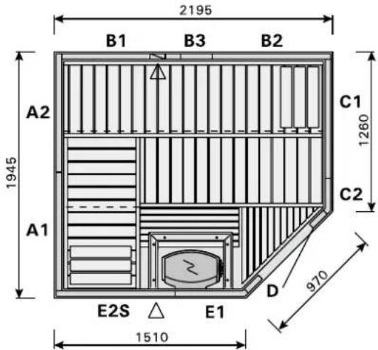
S2220L
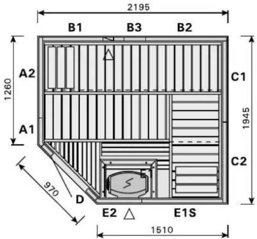
S2220H
(Katto/Tak H1, H2, H3) (Katto/Tak H1, H2, H3)
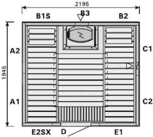
S3020H
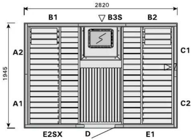
S2222
(Katto/Tak H1, H2, H3) (Katto/Tak H1, H2, H3)
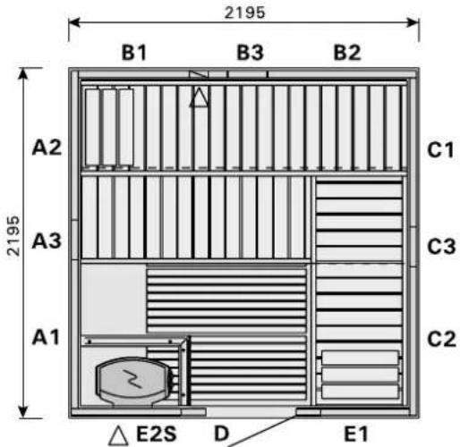
S2222R
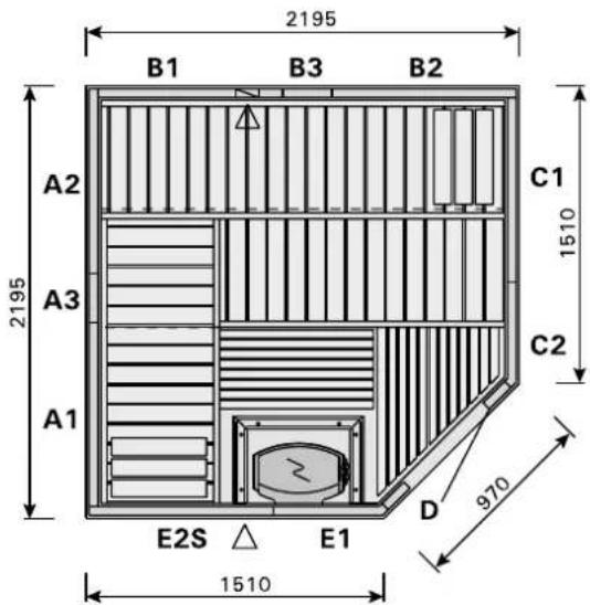
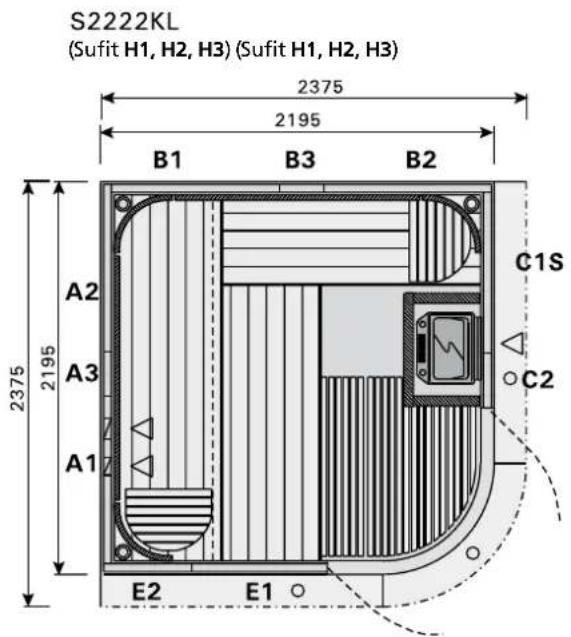
S2222KL
(Katto/Tak H1, H2, H3) (Katto/Tak H1, H2, H3)
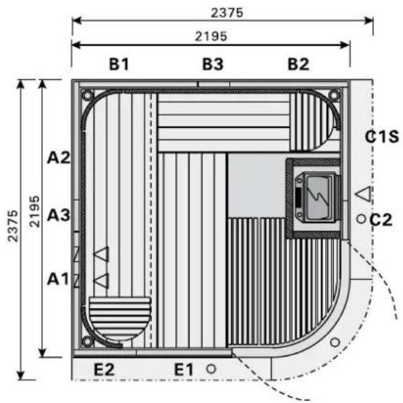
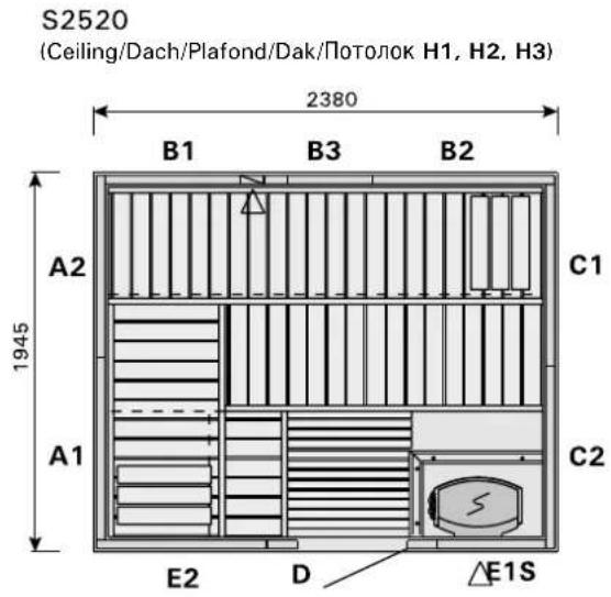
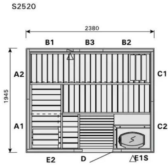
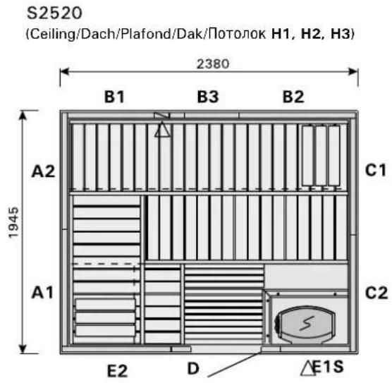
S2520
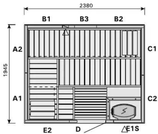
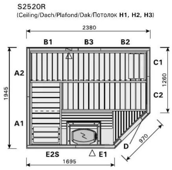
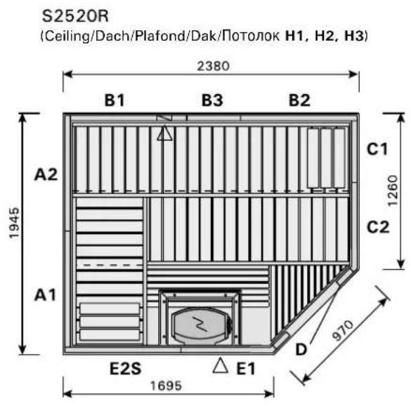
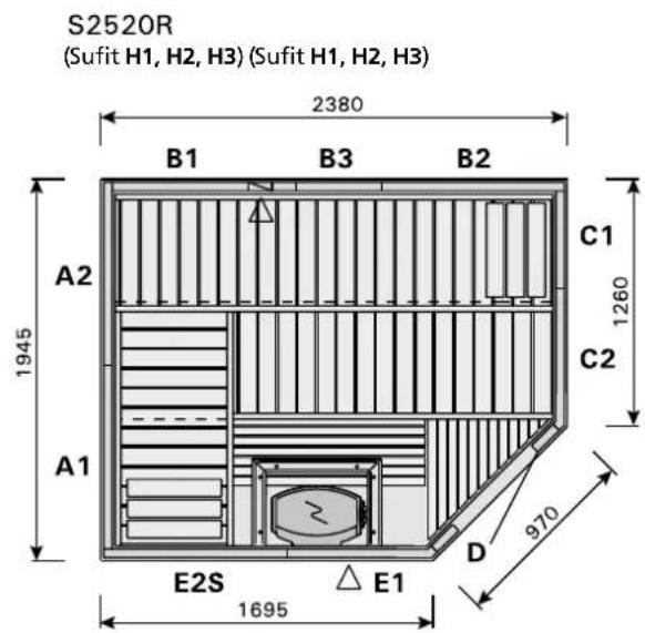
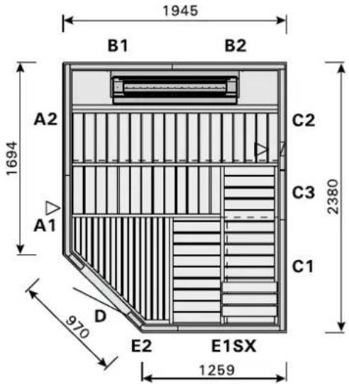
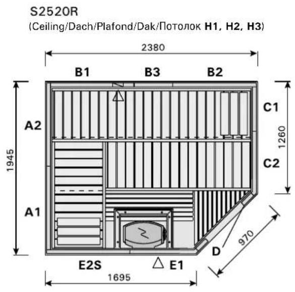
S2520R
(Katto/Tak H1, H2, H3) (Katto/Tak H1, H2, H3)

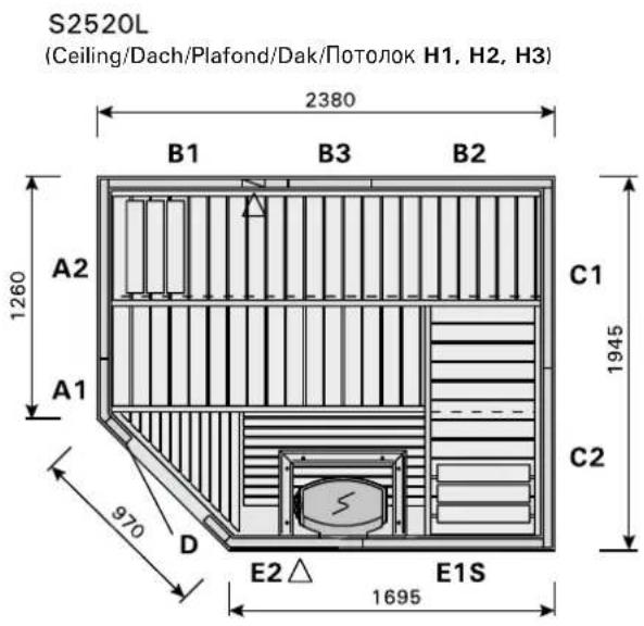
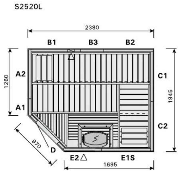
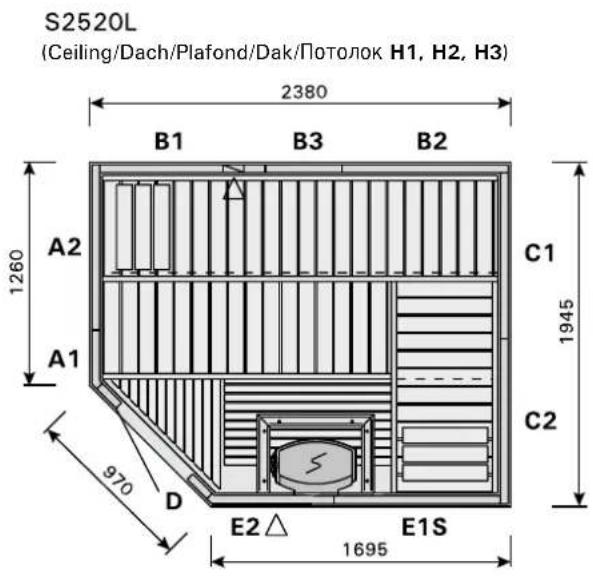
S2520L
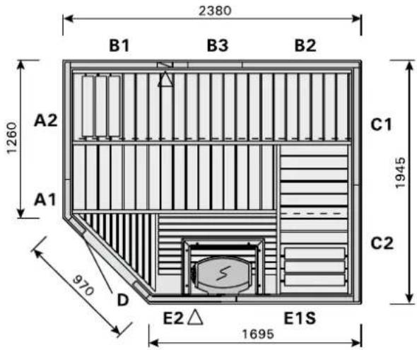
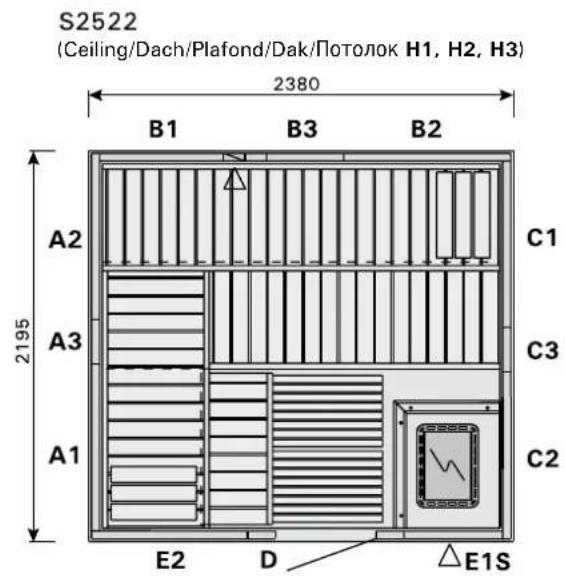
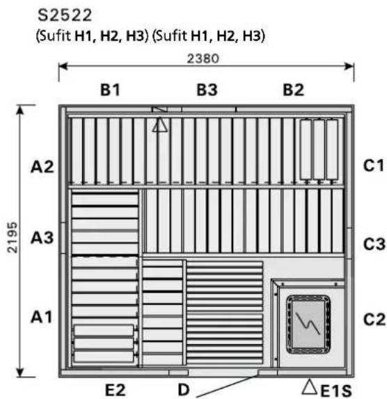
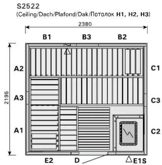
S2522
(Katto/Tak H1, H2, H3) (Katto/Tak H1, H2, H3)
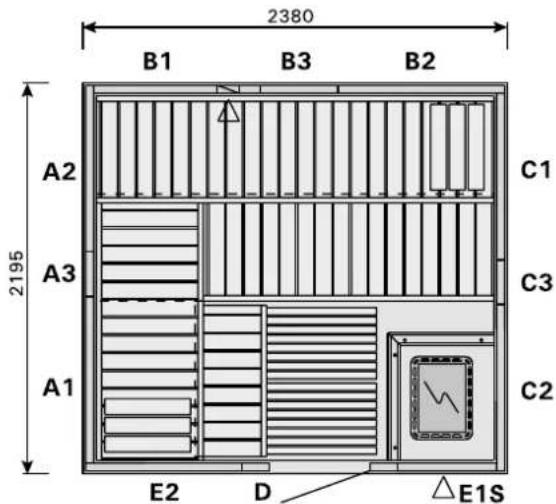
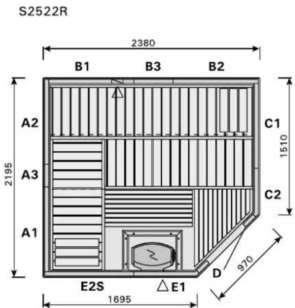
S2522R
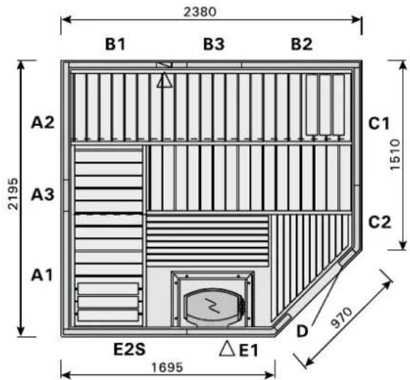
S2522L
(Katto/Tak H1, H2, H3) (Katto/Tak H1, H2, H3)
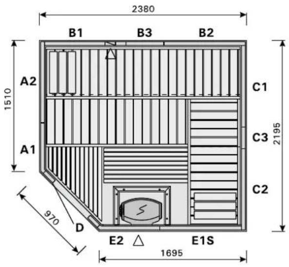
S2522M
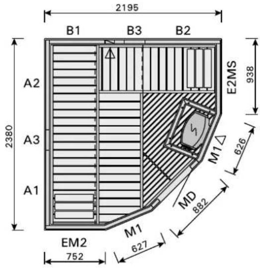
S2020
(Katto/Tak H1, H2, H3) (Katto/Tak H1, H2, H3)
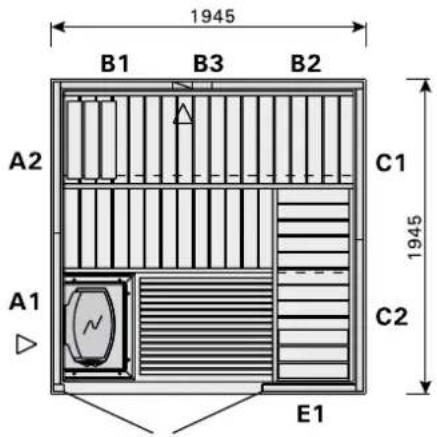
S2020R
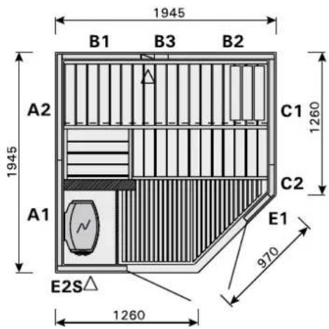
SUB2025L
(Katto/Tak H1, H2, H3) (Katto/Tak H1, H2, H3)
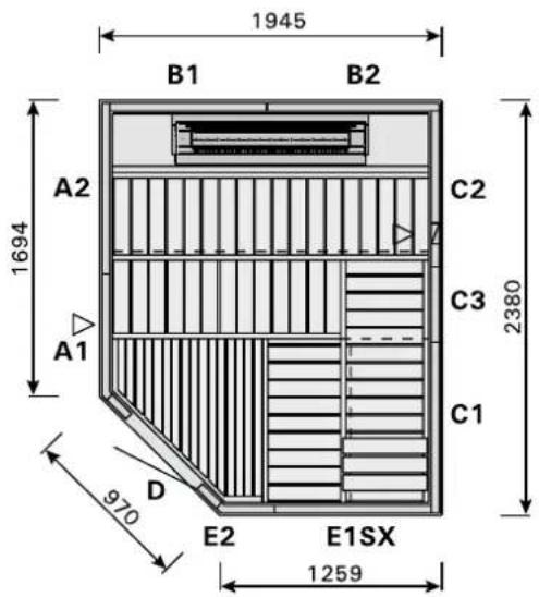
SUB2025R
ASSEMBLY INSTRUCTIONS
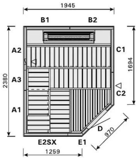
Please read the assembly instructions through before starting. The height of all Variant saunas is 2030 mm (+ adjustable legs 20–40 mm). The minimum room height required for sauna installation is 2150 mm.
You will need the following tools:
- hammer
- drill
- crosshead screwdriver or batterydriven screwdriver (PZ2, PH2 and PZ3).
- fine-toothed saw
- tape measure
- sandpaper
- spirit level
• drill bits (3.5 mm and 10 mm) - stool or step-ladders
- knife (for opening the packages and for small adjustments)
Electrical Installation
Electrical installations may only be carried out by a qualified electrician.
Please note:
- Wood is a natural material, which, despite good storage, can swell, contract or warp. For this reason the assembly of some of the sauna parts may require some force and/or the use of a vice.
- Only use the screws and nails that come with the kit.
- All screw connections should be pre-drilled. Most of the bores have been already made at the factory.
- The room in which the sauna is being assembled must be dry. It is essential to ensure that there is a good flow of air in the room before work commences.
- No impregnants should be used with the sauna's internal parts.
- Round off any sharp, uneven sawed edges with sandpaper.
- If necessary you can fill any holes, joints or other uneven surfaces with a mixture of sawdust and glue.
- The outside of the sauna can be treated with a special sauna protection coat or suitable lacquer. Treated surfaces are easier to clean.
If you are using a special steam heater or other steam generator in your sauna, make sure the pletely dry after use by heating the sauna for a of 15 to 30 minutes (without using steam) and same time keeping the ventilation hole an door open.
If the sauna is equipped with a steam heater and no optional additional ventilation valve (SOFT) has been ordered, this can also be installed at the top of a wall or in the ceiling of a completed sauna.
Assembling the Base Frame
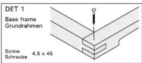
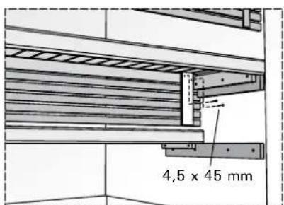
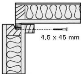
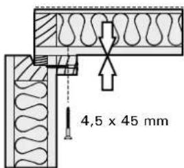
The base frame sections are fastened using 4.5 x 45 mm screws. Please ensure that the base is in the horizontal position (Fig. 2).
Assembling the Walls
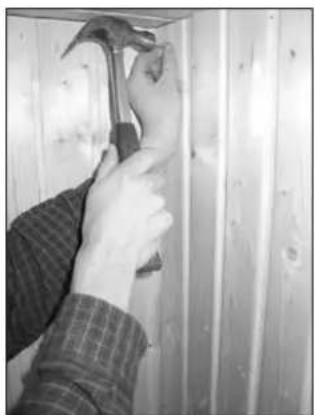
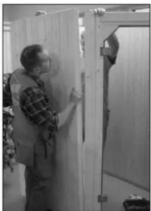
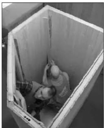
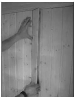
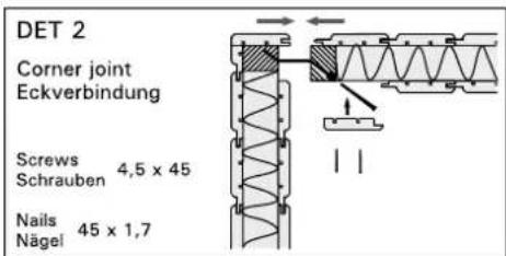
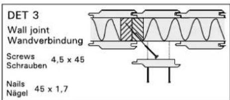
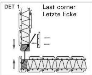
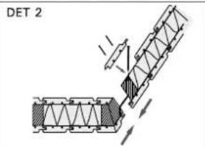
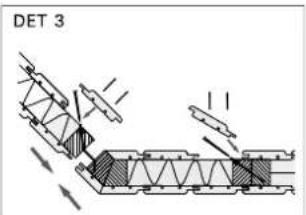
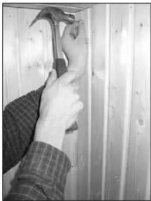
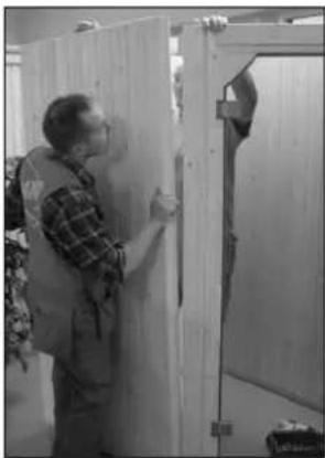
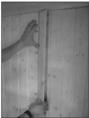
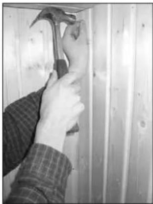
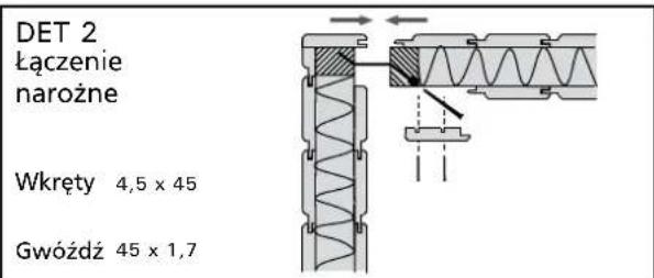
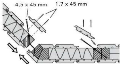
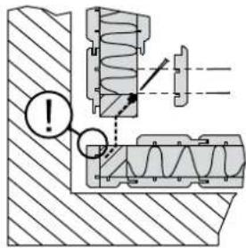
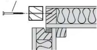
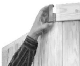
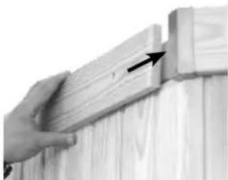
The assembly of the wall panels begins from one of the 90° corners. IMPORTANT! Assembly should come to an end at one of the other right-angled corners. The last panel must tilt outward so that the grooves in the outer panels connect. Fasten the panels using 4,5 x 45 mm screws. The holes are pre-drilled. Use 45 x 1.7 mm nails for the panel boards (Fig. 2 and 6). If the last corner cannot be assembled from outside the sauna, the groove on the last panel board must be completely removed (Fig. 4).
Note! Fastening the door panel cannot be left to last when assembling the sauna.
Please remember to check from above that panel connections are tight.
Achtung!
Assembling the Ceiling Panels
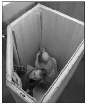
After the walls have been assembled lift the ceiling panels into place. Lower the ceiling panels onto the wall panels making sure that the mouldings on the under-surface of the ceiling panels fit into the grooves at the top of the wall frame.
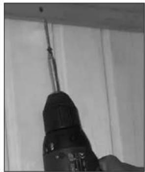
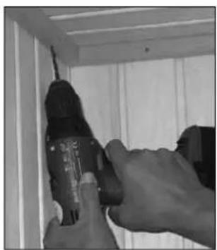
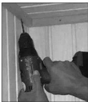
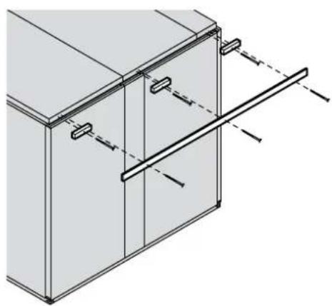
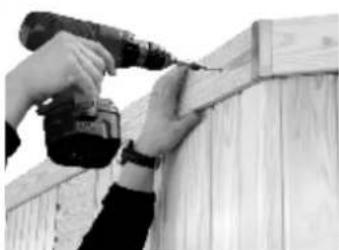
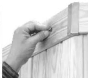
Standing inside the sauna structure, use the mouldings (28 x 28) and the yellow screws (4.5 x 45 mm) to fasten the ceiling panels to the walls (Fig. 5).
Saw off the ceiling mouldings to the right length.
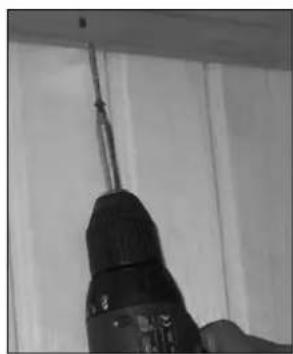
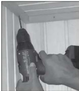
The ceiling strips contain prefabricated holes screws. Be sure to drill 3.5 mm holes for through the panel boards to prevent them from cracking upon installation.
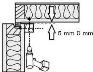
The ceiling mouldings should be screwed first to the walls so that there is a gap of approximately 5 mm between the ceiling and the moulding. When the are screwed into the ceiling the latter sinks into the seal-
ing strip that runs along the top of the walls.
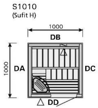
Note! When you are assembling the sauna type S1010, the benches should be positioned inside the sauna itself by passing them over the walls before the ceiling is actually installed, as they can not be turned once inside.
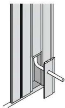
The wall contains ready-made electrical install tubes for the heater and control unit cables. Their ends are visible at the top of the element. The exterior wall contains a detachable panel for the control and there is a similar panel at the bottom of the interior wall for the heater (Fig. 8). Drill holes for the cable in the detachable panel if necessary.
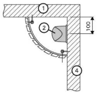
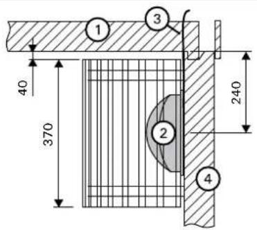
A hole for the light fitting cable shall be drilled diagonally through the upper edge of the wall element (Fig. 9)
or directly through the wall if the cable is allowed to be visible.
Cable holes for a separate thermostat and speakers shall be drilled through the wall or ceiling.
Assembling the Fascia Boards
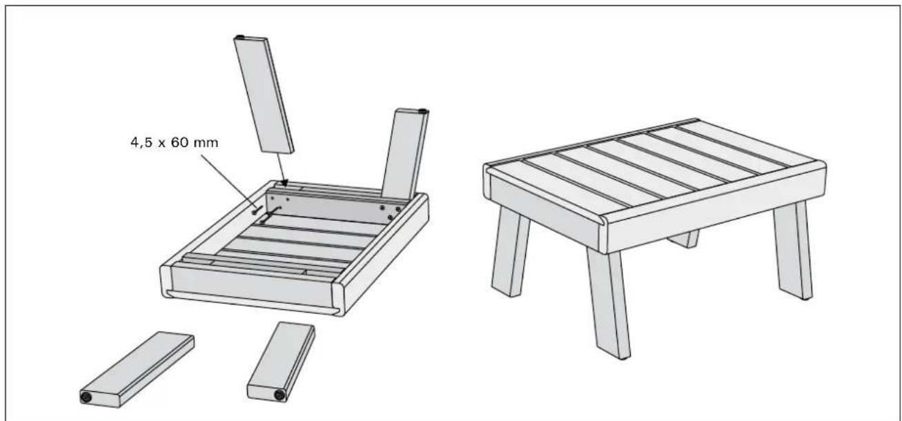
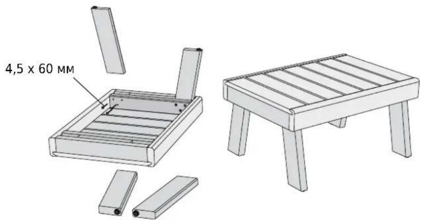
Before assembling the fascia boards (15 x sure that all electrical cables belonging to and the lamp have been fitted and connected correctly. Use 4.5 x 60 mm screws when fastening the filling battens (2) under the fascia boards at distances of 500 to
DE
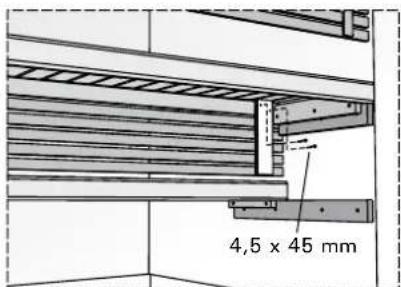
Assembling bench surround (underside of the bench)
Montage der Blende
(Unterseite der Liege)
Figure 11a.
Abbildung 11a.
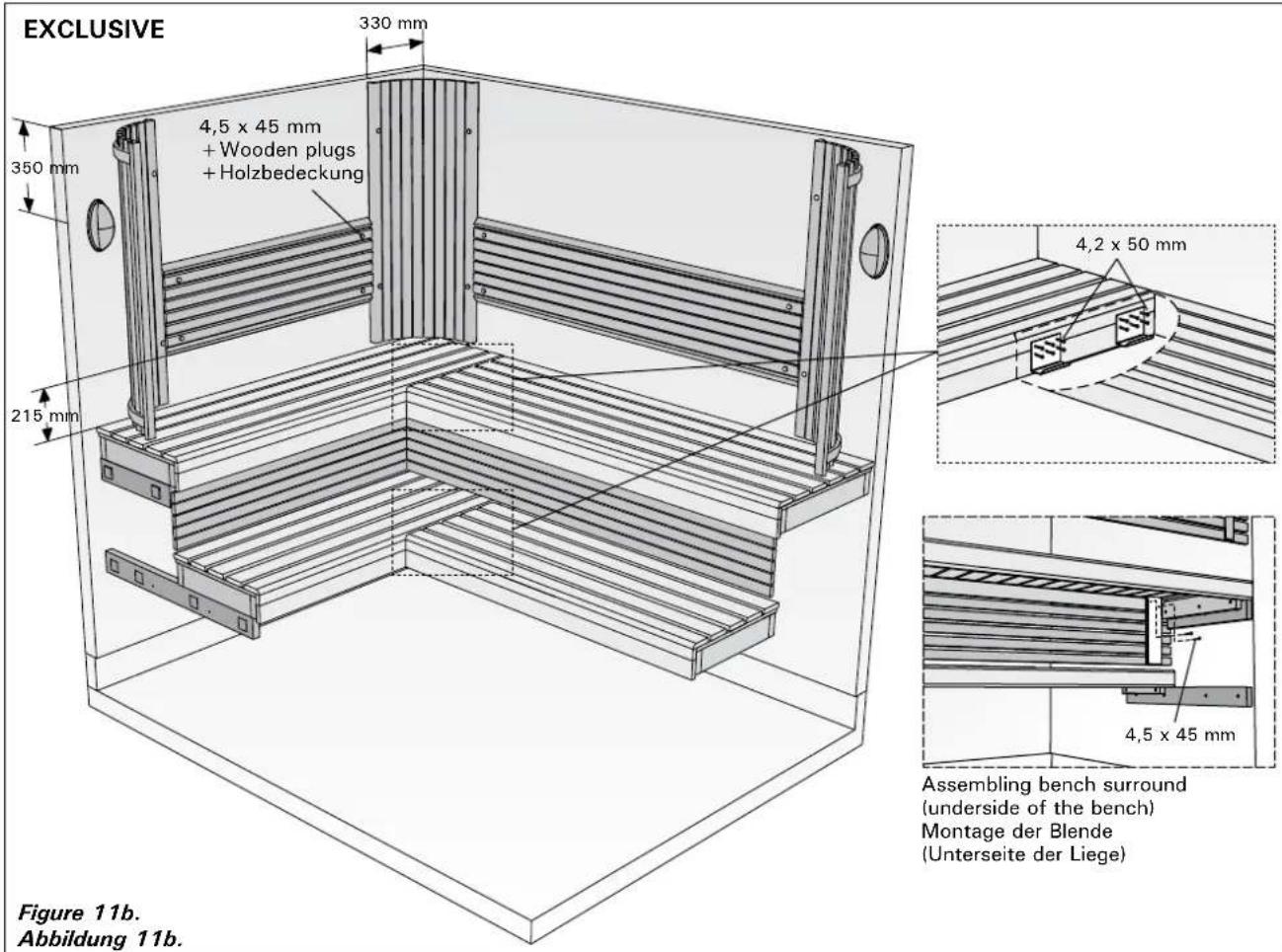
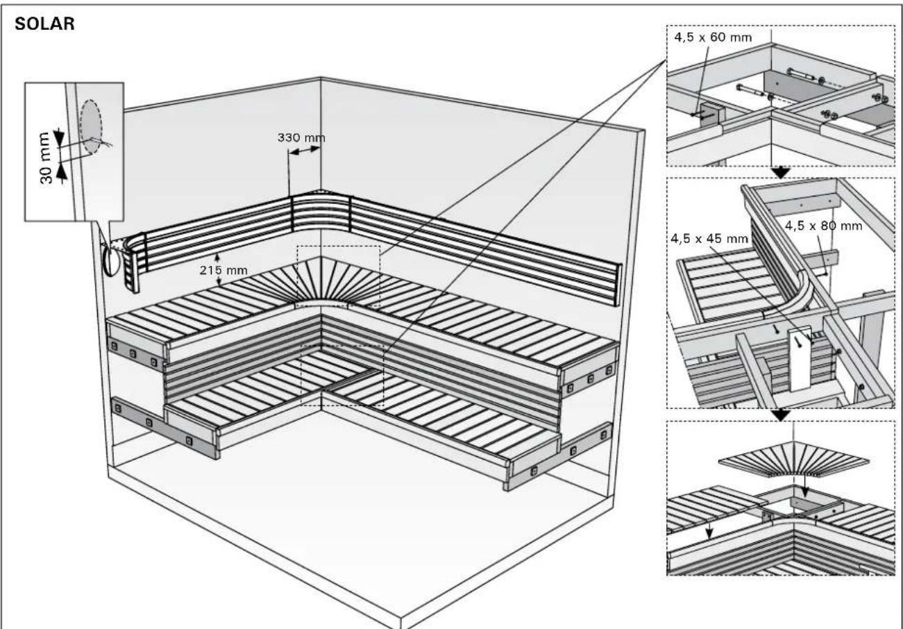
Figure 11c. Abbildung 11c.
VENTURA
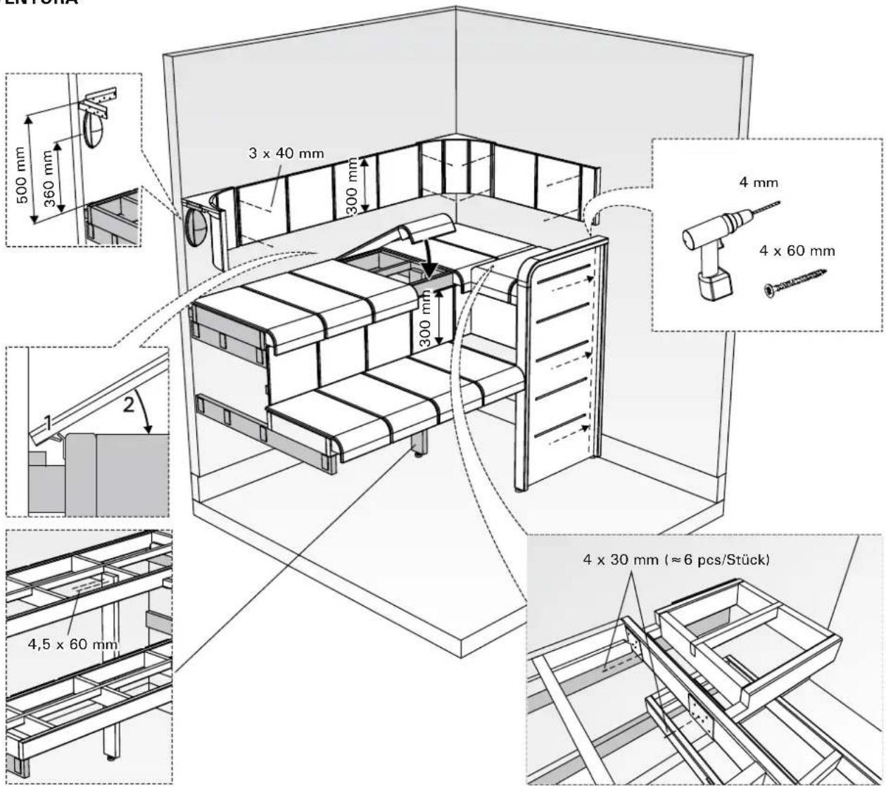
600 mm. The outermost battens need to be as close as possible to the corner.
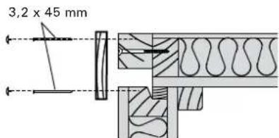
Saw the fascia boards (3) to the right length and use 3.2 × 45 mm screws to fasten them in place.
Assembling the Benches
Fasten the bench supports (32 x 90) using 6 x screws. Fig. 10.
Note! Also lift the lower bench onto the bench supports before fastening the L-bench and bench surro Otherwise, later the fit may be too tight.
Other Information
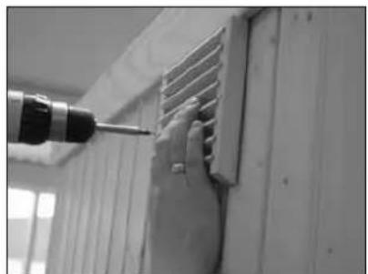
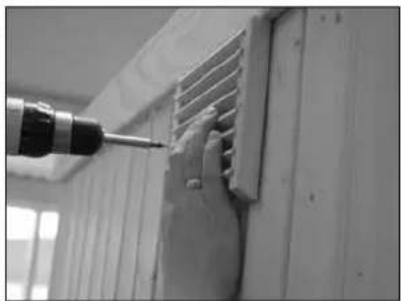
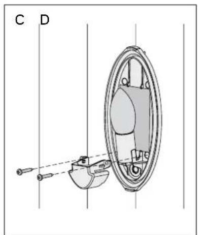
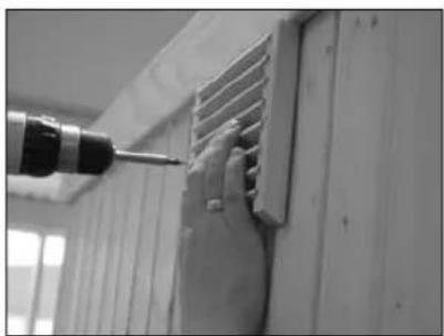
Fasten the ventilation valve and grill using 4.5 x 45 mm screws. Attach the door handle and heater guard as described in accompanying instructions.
Note! If you wish to install the wall heater by the window, first fit the wooden support supplied. Fasten heater to the support accordingly.
Note! If the door leaf does not fit the doorframe tightly along the lock fitting side, it is often due to the fact that the base frame has shifted during assembly. Correct the situation by carefully moving the base frame (whole unit) along the ground in the appropriate direction.
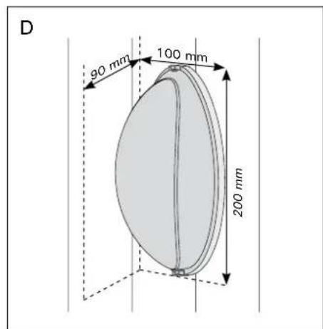
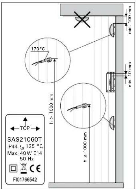
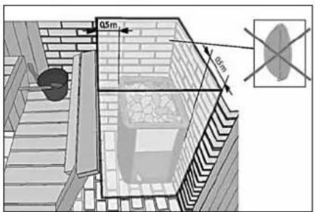
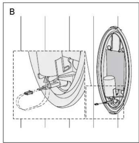
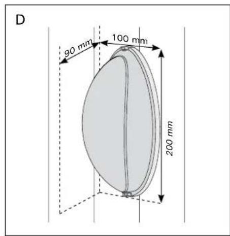
Your sauna is equipped with a sauna lamp. Installation of the sauna lamp is preferable, but not obligatory since the glass door of the sauna allows light into the cabin.
When the lamp is installed these instructions be followed, if the sauna is equipped with control unit:
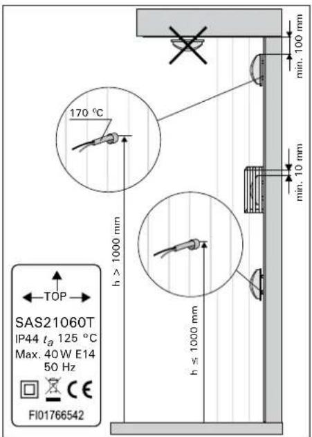
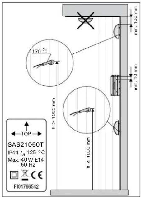
- The lamp should be connected as part of the house lighting circuit and it should be connected to a separate switch. The switch should be located outside the sauna room and should be installed according to the IEE wiring regulations.
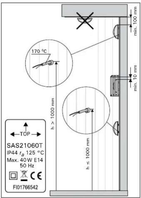
• Supply voltage: 230/240 V, single phase - Light bulb: type E14, recommended 25–40 W (max. 40 W). Bulb is not included.
- Type of supply cable: 2 x 1.5 mm 2 , heat resistant min. 170 °C
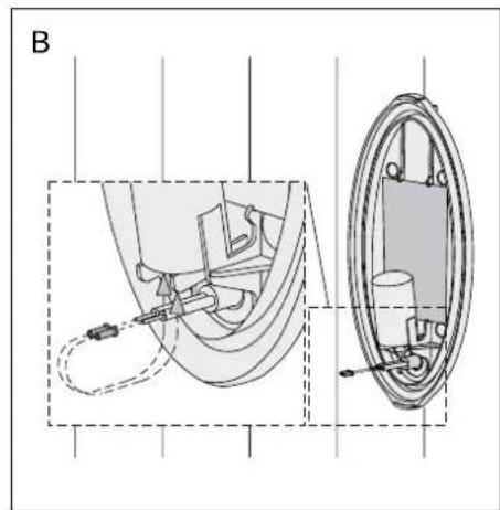
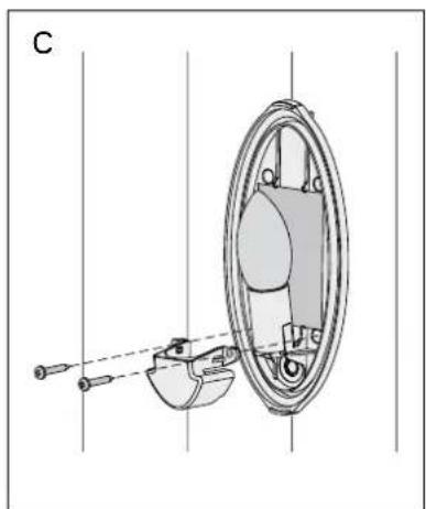
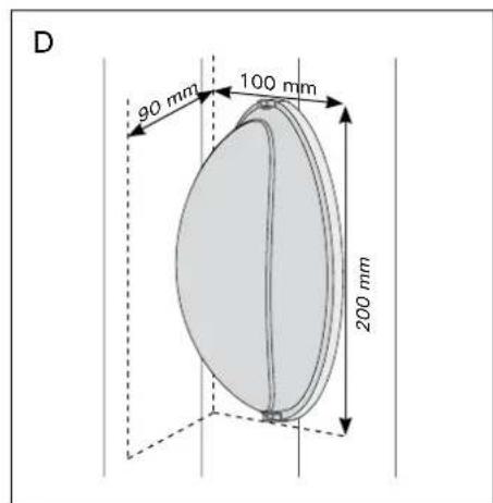
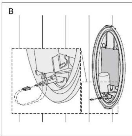
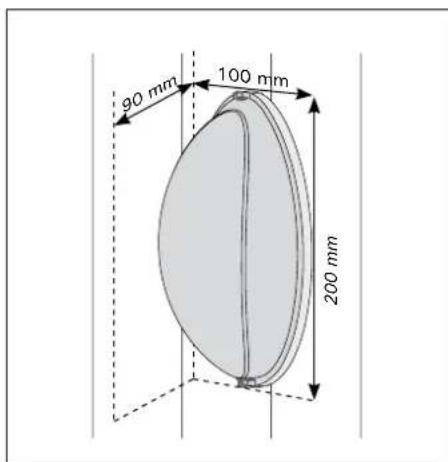
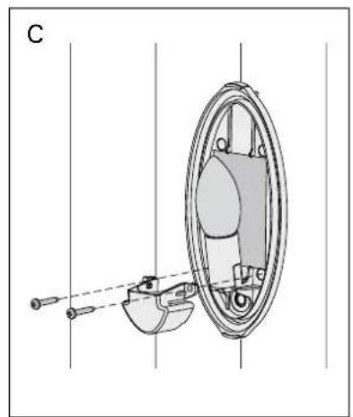
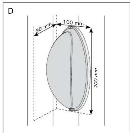
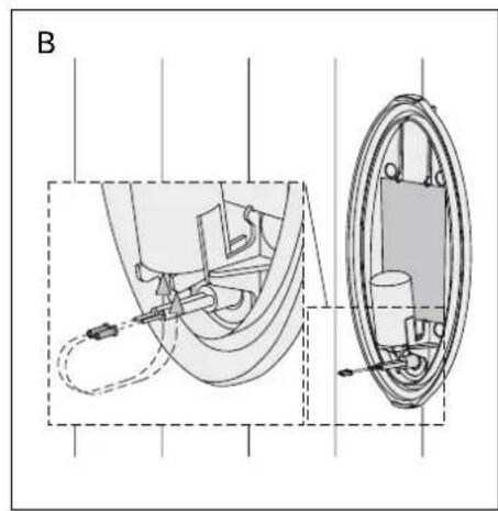
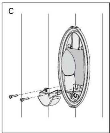
It is necessary to drill a hole through the timber wall for the supply cable. The following pictures show how the electrical connection should be made:
INSTALLATION DES SAUNALICHTS
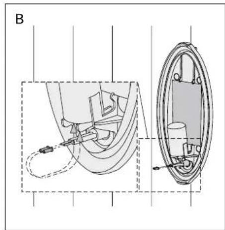
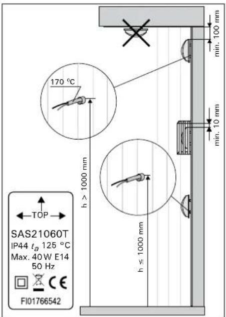
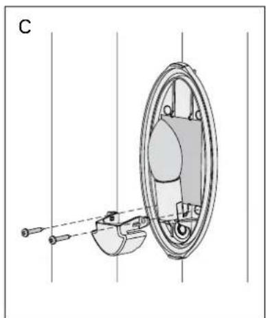
Note! Only a professional electrician is allowed to do the installation. Use only light sources and rated wattages as marked in the luminaire. Switch off the current before installation or service.
S1212
(Ceiling/Dach/Plafond/Dak/Потолок Н)
S1215L
(Ceiling/Dach/Plafond/Dak/Потолок HR)
S1215R
(Ceiling/Dach/Plafond/Dak/Потолок HL)
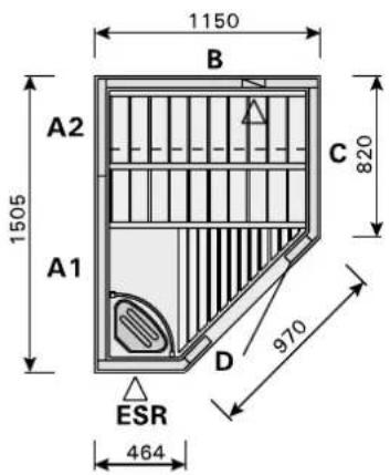
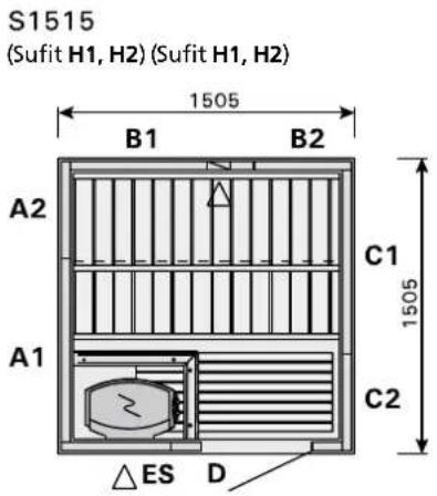
S1515
(Ceiling/Dach/Plafond/Dak/Потолок H1, H2)
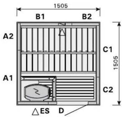
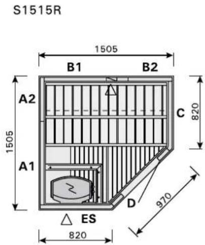
S1515R
(Ceiling/Dach/Plafond/Dak/Потолок H1, H2)
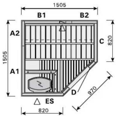
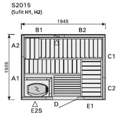
S2015
(Ceiling/Dach/Plafond/Dak/Потолок Н1, Н2)
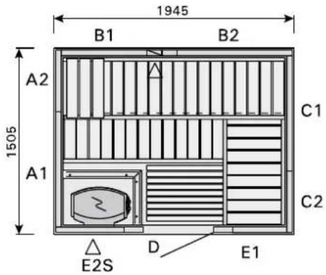
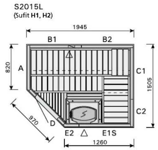
S2015L
(Ceiling/Dach/Plafond/Dak/Потолок H1, H2)
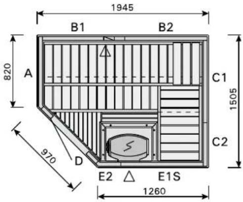
S2015R
(Ceiling/Dach/Plafond/Dak/Потолок H1, H2)
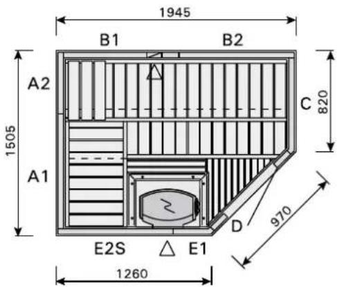
S2020
(Ceiling/Dach/Plafond/Dak/Потолок H1, H2)
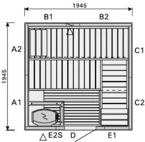
S2020R
(Ceiling/Dach/Plafond/Dak/Потолок H1, H2)
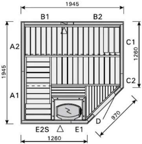
S2220
(Ceiling/Dach/Plafond/Dak/Потолок H1, H2, H3)
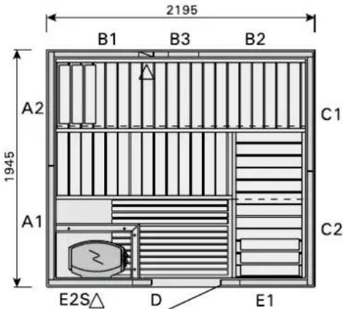
S2220R
(Ceiling/Dach/Plafond/Dak/Потолок H1, H2, H3)
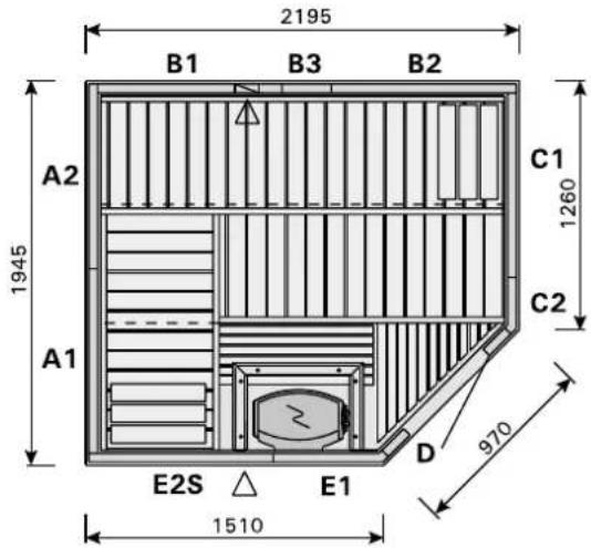
S2220L
(Ceiling/Dach/Plafond/Dak/Потолок H1, H2, H3)
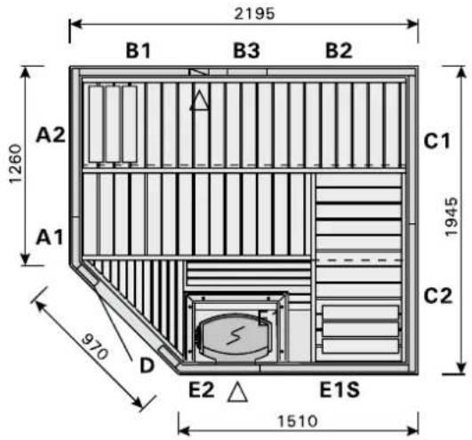
S2220H
(Ceiling/Dach/Plafond/Dak/Потолок H1, H2, H3)
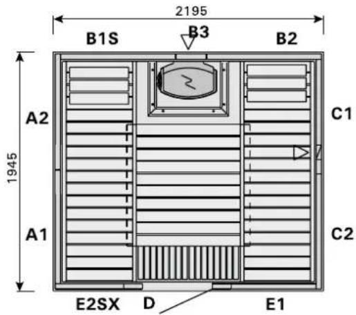
S3020H
(Ceiling/Dach/Plafond/Dak/Потолок H1, H2, H3)
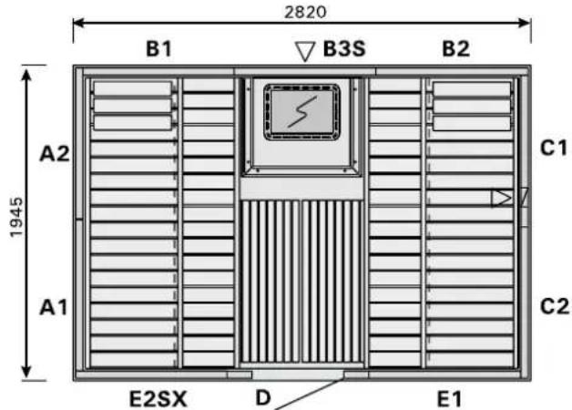
S2222
(Ceiling/Dach/Plafond/Dak/Потолок H1, H2, H3)
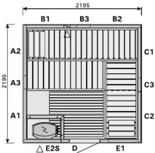
S2222R
(Ceiling/Dach/Plafond/Dak/Потолок H1, H2, H3)
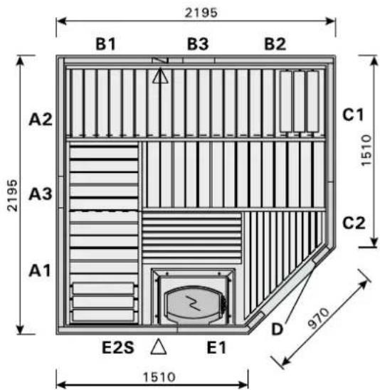
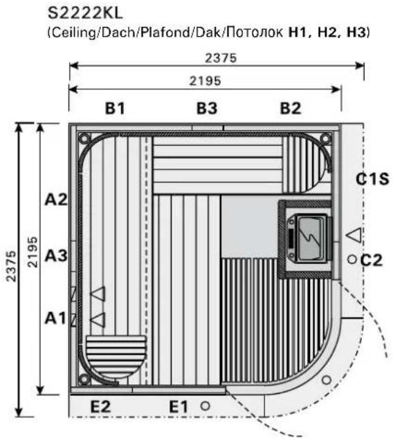
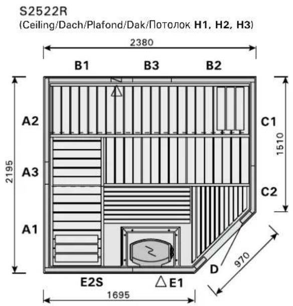
S2522L
(Ceiling/Dach/Plafond/Dak/Потолок H1, H2, H3)
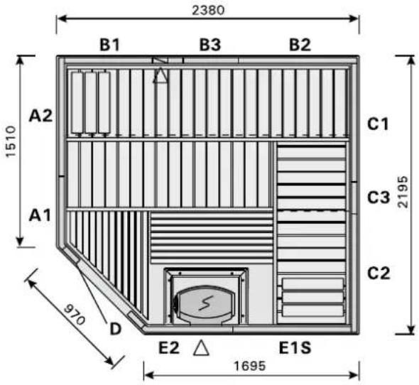
S2522M
(Ceiling/Dach/Plafond/Dak/Потолок H1, H2, H3)
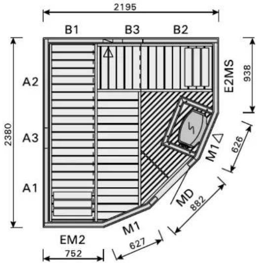
S2020
(Ceiling/Dach/Plafond/Dak/Потолок H1, H2, H3)
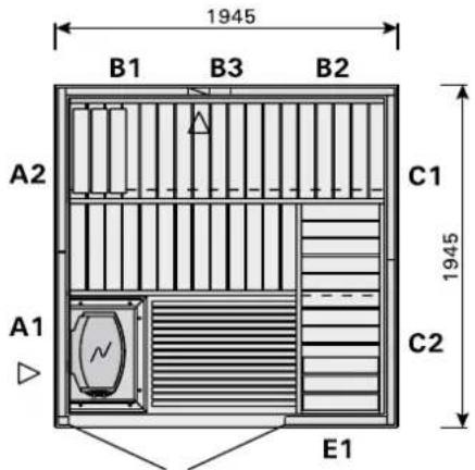
S2020R
(Ceiling/Dach/Plafond/Dak/Потолок H1, H2, H3)
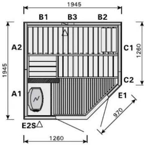
SUB2025L
(Ceiling/Dach/Plafond/Dak/Потолок H1, H2, H3)
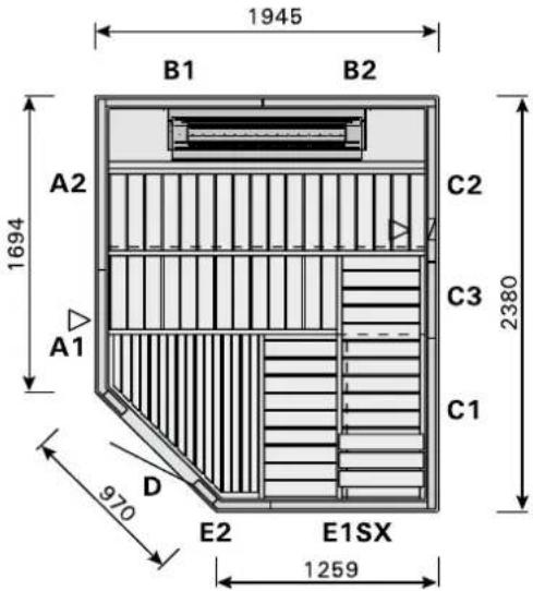
SUB2025R
(Ceiling/Dach/Plafond/Dak/Потолок H1, H2, H3)
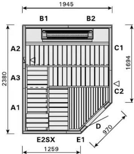
INSTRUCTIONS POUR L'INSTALLATION

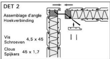
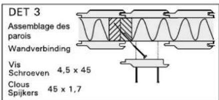
Schéma 4. Dernier joint dans le coin de la pièce Afbeelding 4. Laatste verbinding in hoek van de ruimte
S1010
(Ceiling/Dach/Plafond/Dak/Потолок Н)
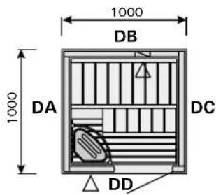
S1212
(Ceiling/Dach/Plafond/Dak/Потолок Н)
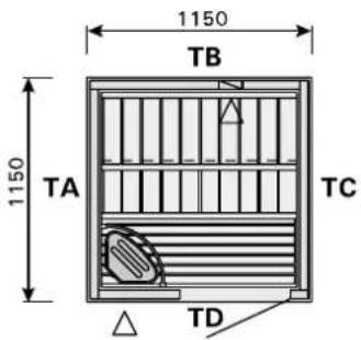
S1215L
(Ceiling/Dach/Plafond/Dak/Потолок HR)
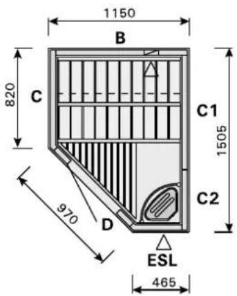
S1215R
(Ceiling/Dach/Plafond/Dak/Потолок HL)
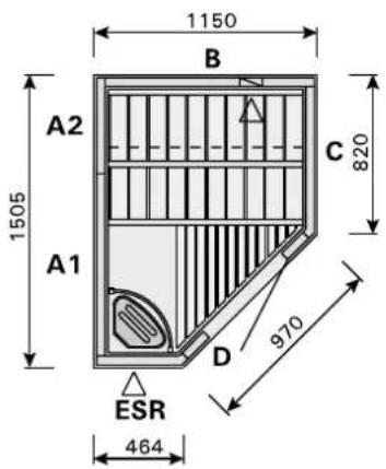
S1515
(Ceiling/Dach/Plafond/Dak/Потолок H1, H2)
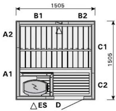
S1515R
(Ceiling/Dach/Plafond/Dak/Потолок H1, H2)
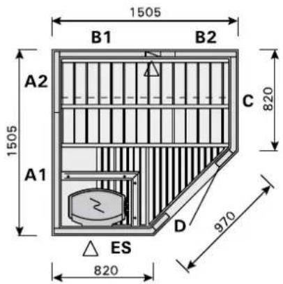
S2015
(Ceiling/Dach/Plafond/Dak/Потолок Н1, Н2)
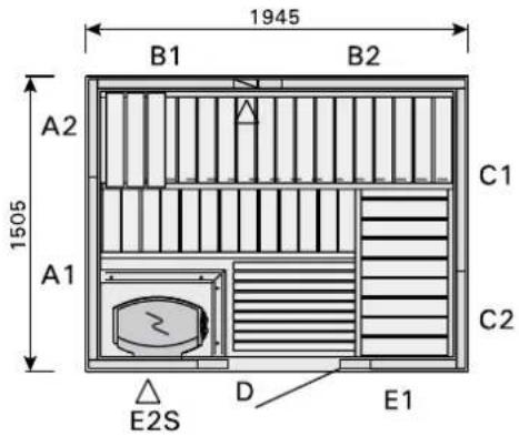
S2015L
(Ceiling/Dach/Plafond/Dak/Потолок H1, H2)
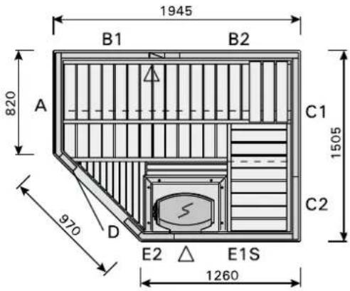
S2015R
(Ceiling/Dach/Plafond/Dak/Потолок H1, H2)
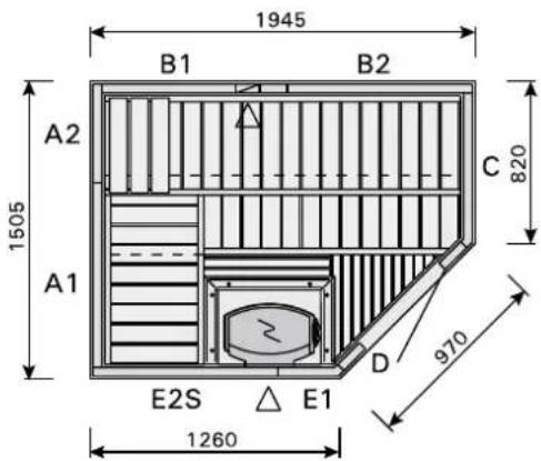
S2020
(Ceiling/Dach/Plafond/Dak/Потолок H1, H2)
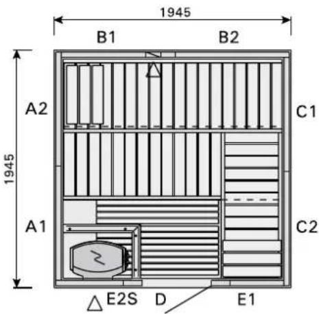
S2020R
(Ceiling/Dach/Plafond/Dak/Потолок H1, H2)
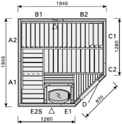
S2220
(Ceiling/Dach/Plafond/Dak/Потолок H1, H2, H3)
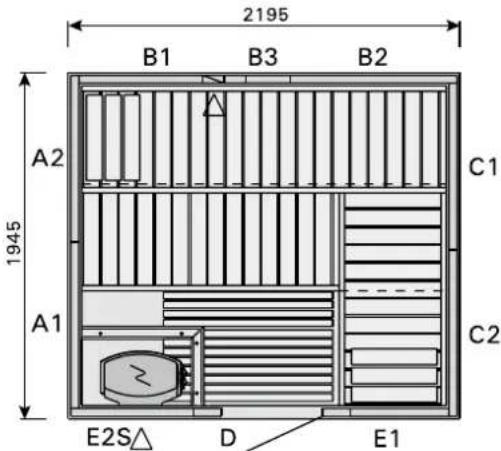
S2220R
(Ceiling/Dach/Plafond/Dak/Потолок H1, H2, H3)
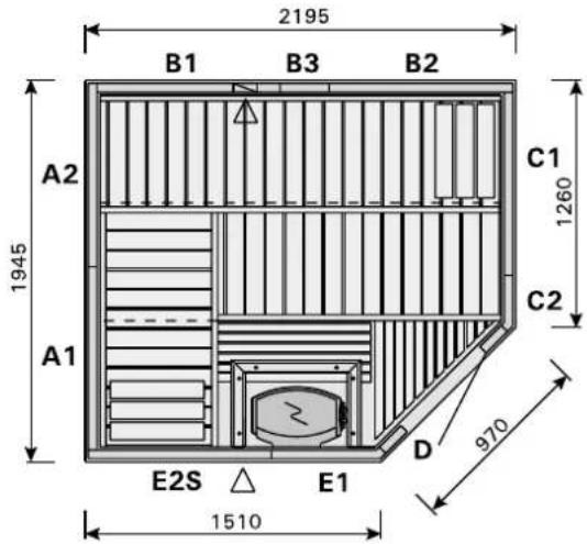
S2220L
(Ceiling/Dach/Plafond/Dak/Потолок H1, H2, H3)
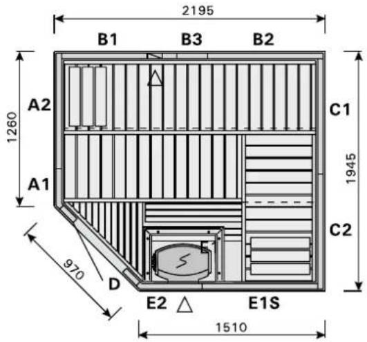
S2220H
(Ceiling/Dach/Plafond/Dak/Потолок H1, H2, H3)
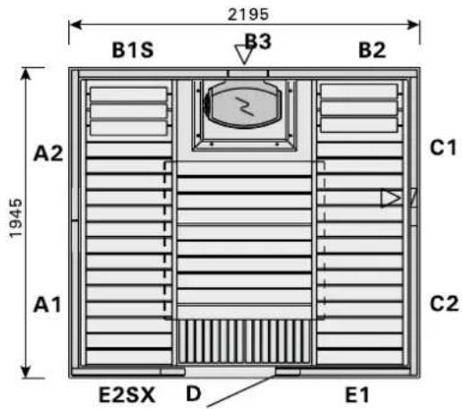
S3020H
(Ceiling/Dach/Plafond/Dak/Потолок H1, H2, H3)
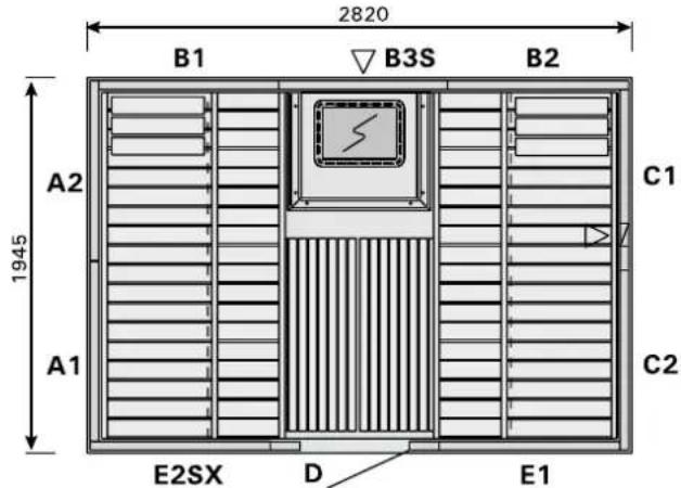
S2222
(Ceiling/Dach/Plafond/Dak/Потолок H1, H2, H3)
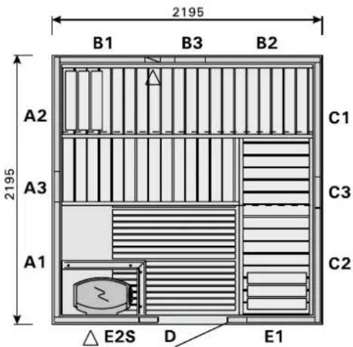
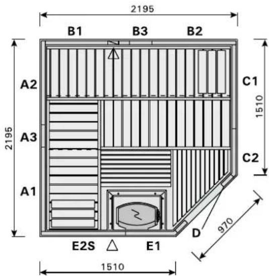
S2222R
(Ceiling/Dach/Plafond/Dak/Потолок H1, H2, H3)
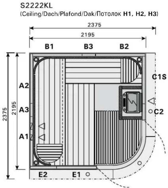
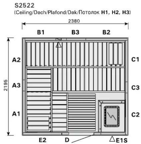
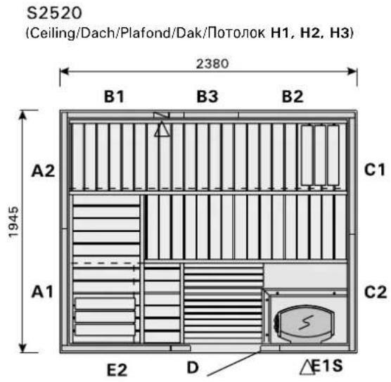
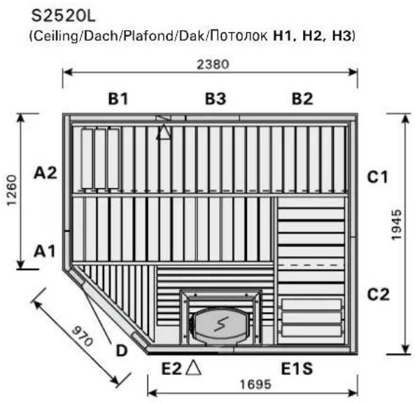
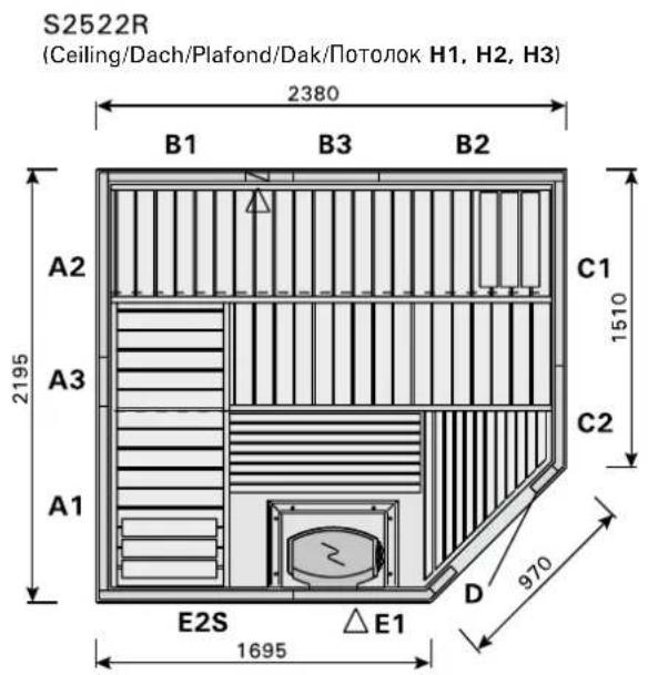
S2522L
(Ceiling/Dach/Plafond/Dak/Потолок H1, H2, H3)
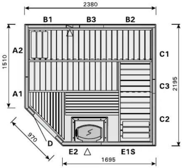
S2522M
(Ceiling/Dach/Plafond/Dak/Потолок H1, H2, H3)
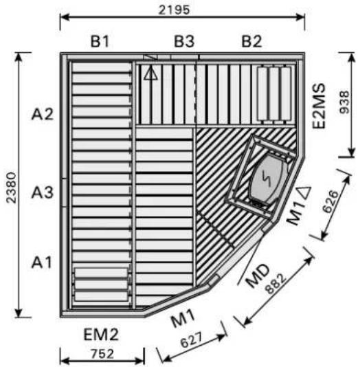
S2020
(Ceiling/Dach/Plafond/Dak/Потолок H1, H2, H3)
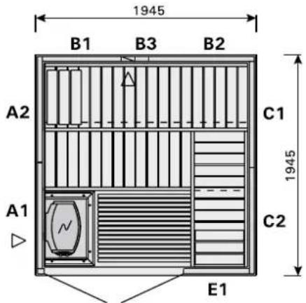
S2020R
(Ceiling/Dach/Plafond/Dak/Потолок H1, H2, H3)
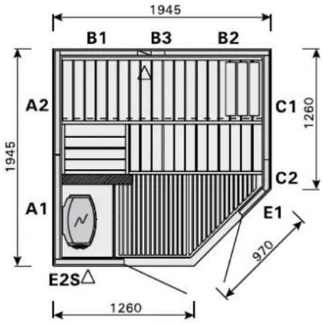
SUB2025L
(Ceiling/Dach/Plafond/Dak/Потолок H1, H2, H3)
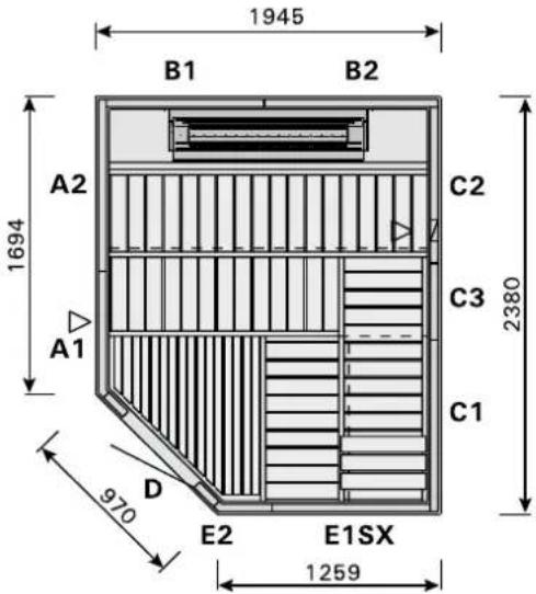
SUB2025R
(Ceiling/Dach/Plafond/Dak/Потолок H1, H2, H3)
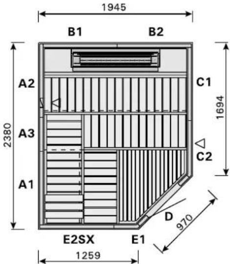
INSTRUKCJE MONTAŻU
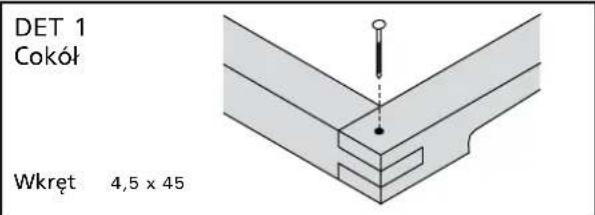
DET 1
Rysunek 3.
1.2.3.
Rysunek 4.
4,5 x 60 mm
Rysunek 5.
W rogu blisko
sufitu
Pod ławką
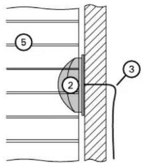
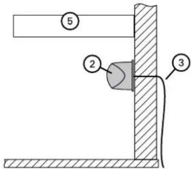
- Sufit
- Lampa
- Kabel
- Ściana
- Ławka
Rysunek 9.
INSTALACJA LAMPY W SAUNIE
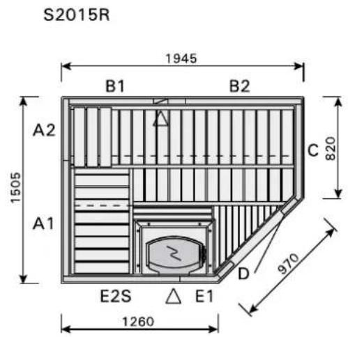
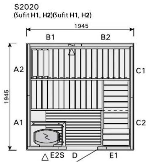
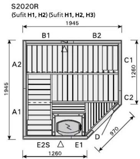
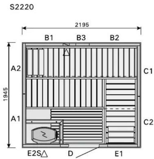
S2220R
(Sufit H1, H2, H3) (Sufit H1, H2, H3)
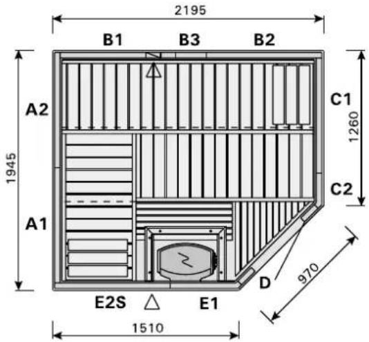
S2220L
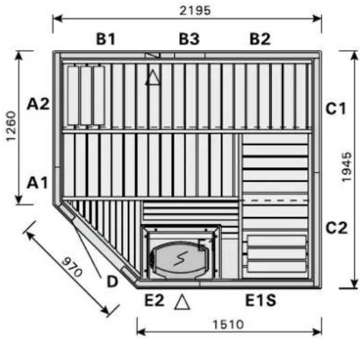
S2220H
(Sufit H1, H2, H3) (Sufit H1, H2, H3)
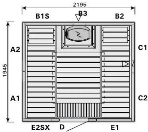
S3020H
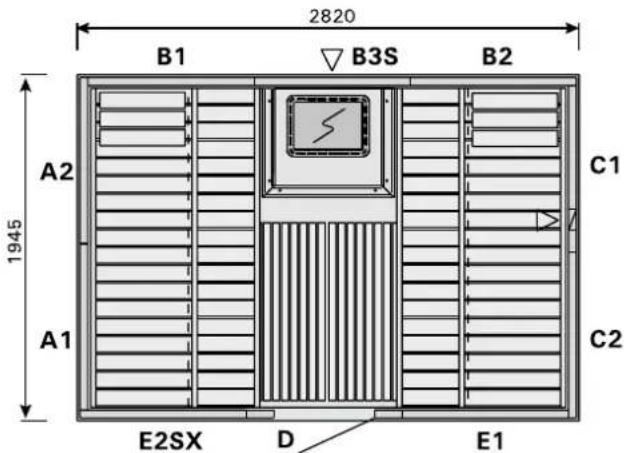
S2222
(Sufit H1, H2, H3) (Sufit H1, H2, H3)
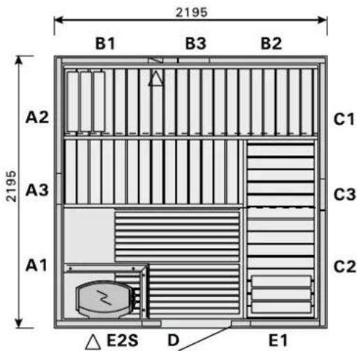
S2222R
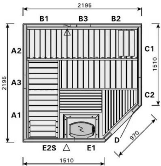
S2522L
(Sufit H1, H2, H3) (Sufit H1, H2, H3)
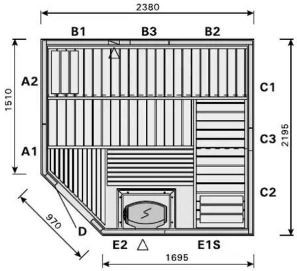
S2522M
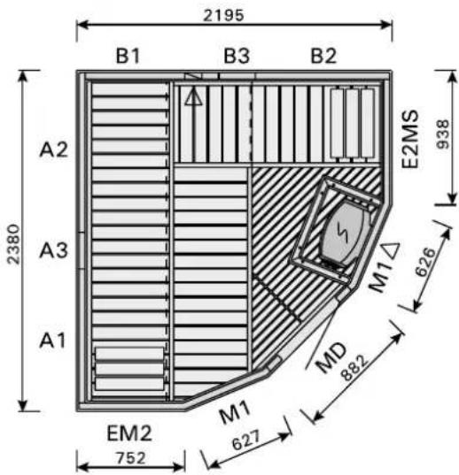
S2020
(Sufit H1, H2, H3) (Sufit H1, H2, H3)
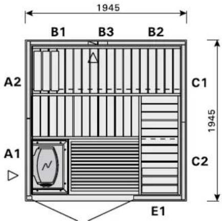
S2020R
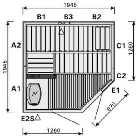
SUB2025L
(Sufit H1, H2, H3) (Sufit H1, H2, H3)
SUB2025R
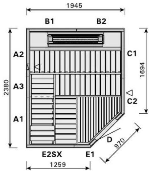
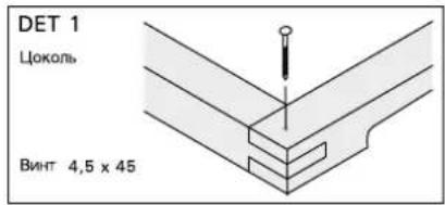
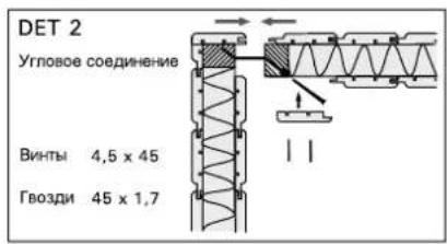
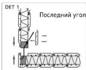
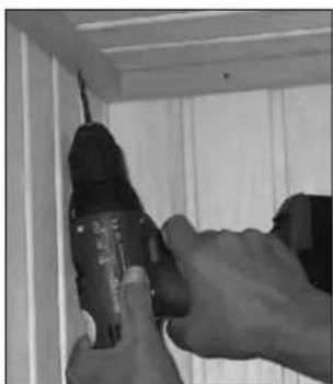
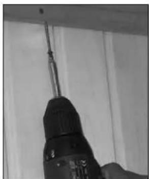
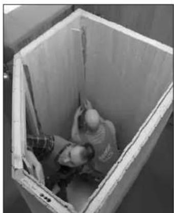
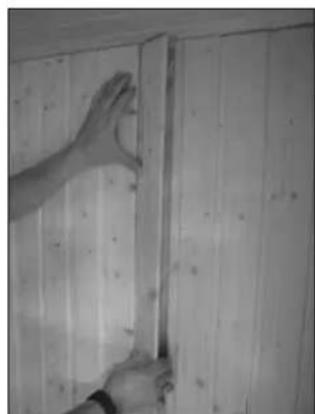
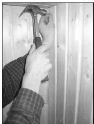
Рисунок 5.
RU
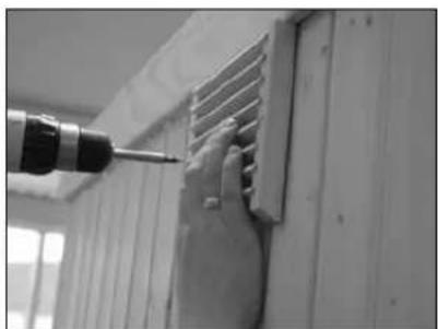
Рисунок 12.
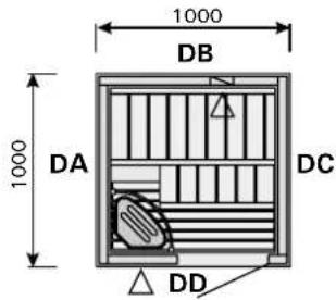
S1010
(Ceiling/Dach/Plafond/Dak/Потолок Н)
S1212
(Ceiling/Dach/Plafond/Dak/Потолок Н)
S1215L
(Ceiling/Dach/Plafond/Dak/Потолок HR)
S1215R
(Ceiling/Dach/Plafond/Dak/Потолок HL)
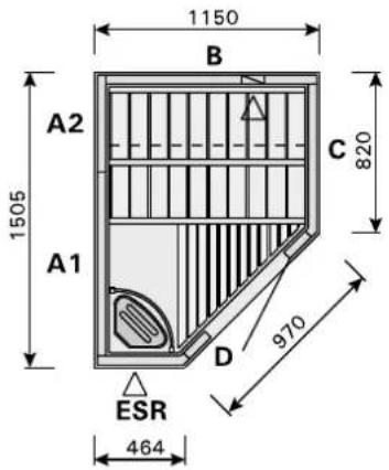
S1515
(Ceiling/Dach/Plafond/Dak/Потолок H1, H2)
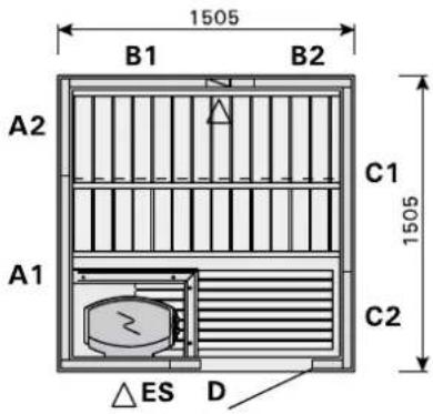
S1515R
(Ceiling/Dach/Plafond/Dak/Потолок H1, H2)
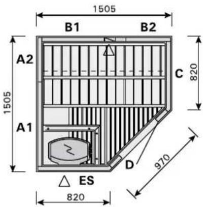
S2015
(Ceiling/Dach/Plafond/Dak/Потолок H1, H2)
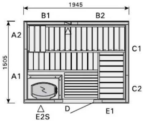
S2015L
(Ceiling/Dach/Plafond/Dak/Потолок H1, H2)
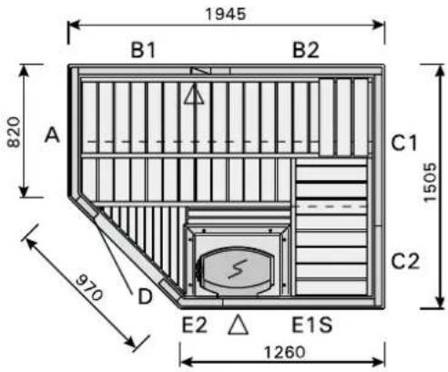
S2015R
(Ceiling/Dach/Plafond/Dak/Потолок H1, H2)
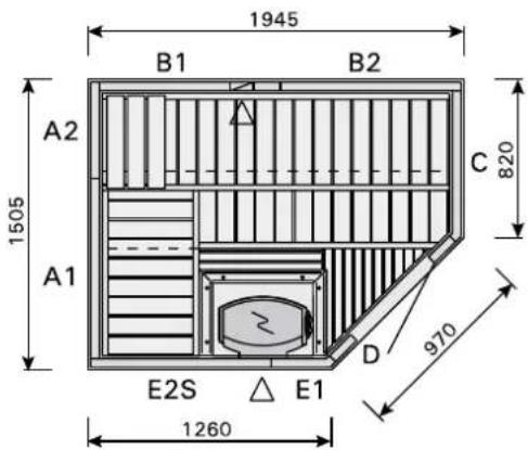
S2020
(Ceiling/Dach/Plafond/Dak/Потолок H1, H2)
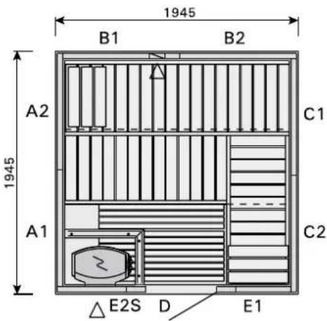
S2020R
(Ceiling/Dach/Plafond/Dak/Потолок H1, H2)
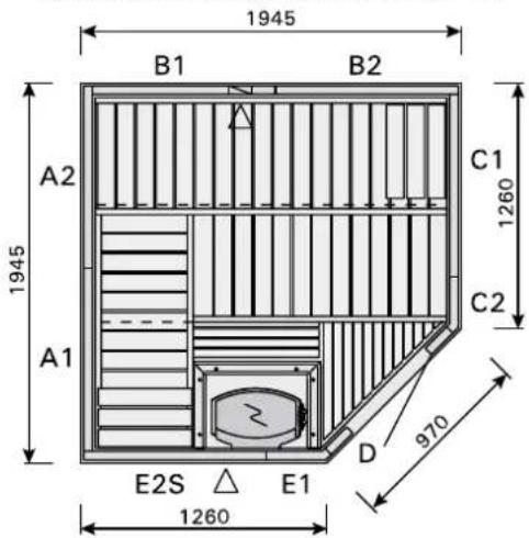
S2220
(Ceiling/Dach/Plafond/Dak/Потолок H1, H2, H3)
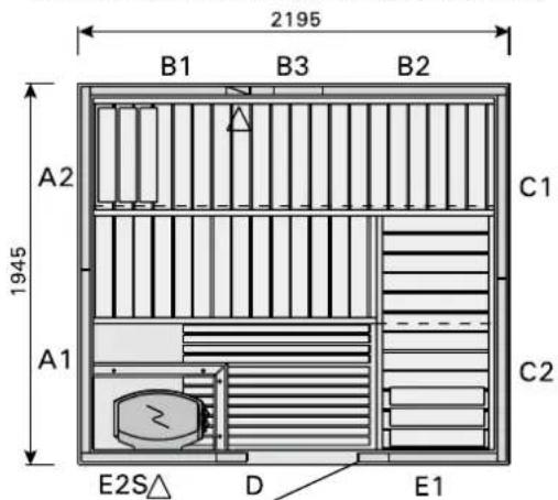
S2220R
(Ceiling/Dach/Plafond/Dak/Потолок H1, H2, H3)
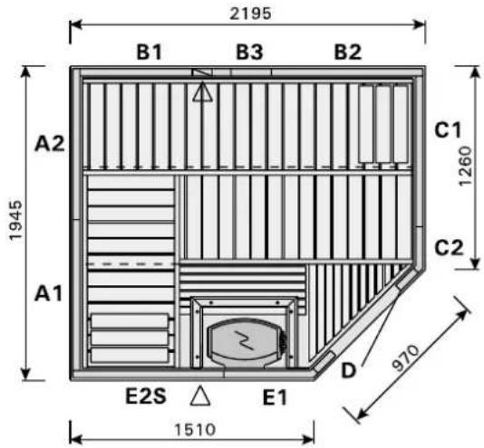
S2220L
(Ceiling/Dach/Plafond/Dak/Потолок H1, H2, H3)
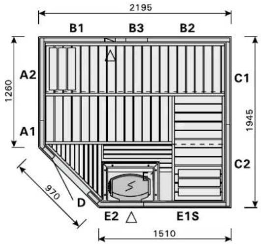
S2220H
(Ceiling/Dach/Plafond/Dak/Потолок H1, H2, H3)
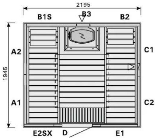
S3020H
(Ceiling/Dach/Plafond/Dak/Потолок H1, H2, H3)
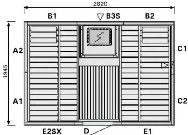
S2222
(Ceiling/Dach/Plafond/Dak/Потолок H1, H2, H3)
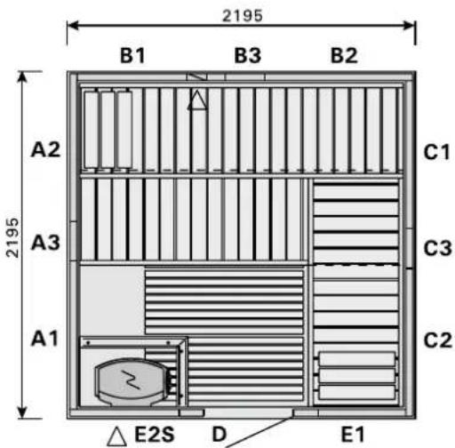
S2222R
(Ceiling/Dach/Plafond/Dak/Потолок H1, H2, H3)
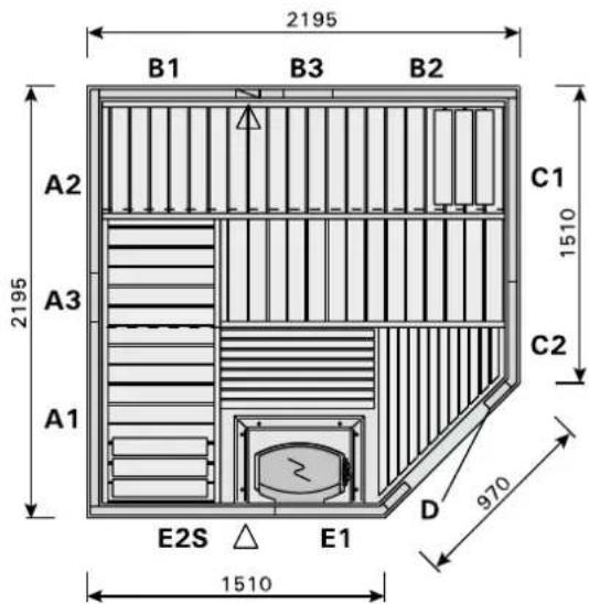
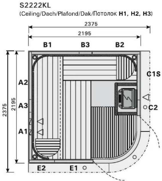
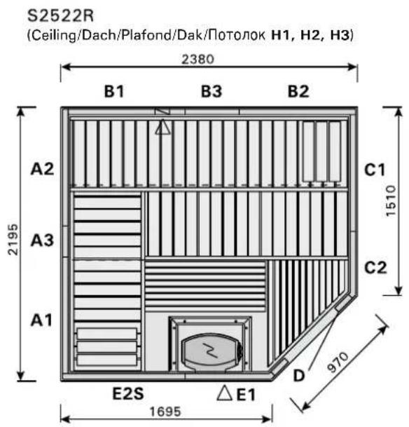
S2522L
(Ceiling/Dach/Plafond/Dak/Потолок H1, H2, H3)
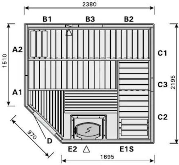
S2522M
(Ceiling/Dach/Plafond/Dak/Потолок H1, H2, H3)
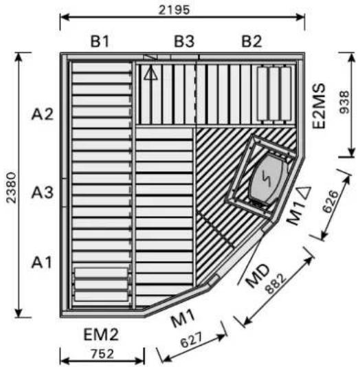
S2020
(Ceiling/Dach/Plafond/Dak/Потолок H1, H2, H3)
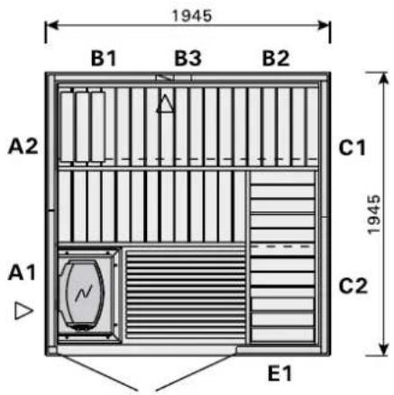
S2020R
(Ceiling/Dach/Plafond/Dak/Потолок H1, H2, H3)
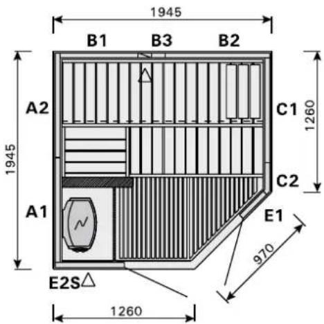
SUB2025L
(Ceiling/Dach/Plafond/Dak/Потолок H1, H2, H3)
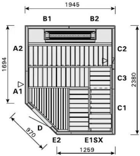
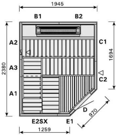
SUB2025R
(Ceiling/Dach/Plafond/Dak/Потолок Н1, Н2, Н3)


- ASSEMBLY INSTRUCTIONS
- YOU WILL NEED THE FOLLOWING TOOLS
- ELECTRICAL INSTALLATION
- PLEASE NOTE
- ASSEMBLING THE BASE FRAME
- ASSEMBLING THE WALLS
- ACHTUNG
- ASSEMBLING THE CEILING PANELS
- ASSEMBLING THE FASCIA BOARDS
- DE
- ASSEMBLING THE BENCHES
- OTHER INFORMATION
- INSTALLATION DES SAUNALICHTS
- INSTRUCTIONS POUR L'INSTALLATION
- INSTRUKCJE MONTAŻU
- INSTALACJA LAMPY W SAUNIE
- RU
Brand : HARVIA
Model : Variant S2520R
Category : Sauna