
TOPS3363 - Laboratory power supply VOLTCRAFT - Free user manual and instructions
Find the device manual for free TOPS3363 VOLTCRAFT in PDF.

| Brand | VOLTCRAFT |
| Model | TOPS3363 |
| Category | Laboratory power supply |
| Output voltage | 1 - 36 V/DC |
| Output current | 0.25 - 3 A |
| Maximum output power | 100 W |
| Display resolution | 0.01 V / 0.001 A |
| Voltage display accuracy | <5 V: ±0.05 V ; ≥5 V: ±(0.2% + 0.05 V) |
| Current display accuracy | ≤1 A: ±0.015 A ; >1 A: ±(0.5% + 0.006 A) |
| Residual ripple (p-p) | ≤150 mV |
| USB outputs | 2x 5 V/DC, max. 1.8 A |
| Power supply | 100 - 240 V/AC, 50/60 Hz |
| Maximum consumption | 1.6 A (at 230 V approx. 0.83 A) |
| Protection class | 1 |
| Cooling | Convection |
| Dimensions (W x H x D) | 70 x 150 x 250 mm |
| Weight | 2 kg |
| Mains fuse | 5x20 mm, T2A/250 V, inert |
| Operating temperature | +5 °C to +40 °C |
| Relative humidity | 85% max, non-condensing |
| Operating altitude | Up to 2000 m |
| Pollution degree | 2 |
| Efficiency | ≥80.5% |
| Power factor (active PFC) | >0.9 |
| Main functions | Digital adjustment of voltage and current, fine/coarse mode, independent DC and USB outputs, overload and short-circuit protection, thermal shutdown |
| Maintenance and cleaning | Disconnect before cleaning; use a dry, anti-static, lint-free cloth; replace the mains fuse only with an identical model |
| Safety | Do not open the device, use a grounded outlet, do not expose to humidity or explosive atmospheres, follow the instructions in the manual |
| Spare parts and repairability | Mains fuse replaceable by user; any other repair must be carried out by a qualified technician |
| General information | Compliant with European directives LVD 2006/95/EC and EN 61010; supplied with power cord, a pair of test leads with crocodile clips and user manual |
Frequently Asked Questions - TOPS3363 VOLTCRAFT
User questions about TOPS3363 VOLTCRAFT
0 question about this device. Answer the ones you know or ask your own.
Ask a new question about this device
Download the instructions for your Laboratory power supply in PDF format for free! Find your manual TOPS3363 - VOLTCRAFT and take your electronic device back in hand. On this page are published all the documents necessary for the use of your device. TOPS3363 by VOLTCRAFT.
USER MANUAL TOPS3363 VOLTCRAFT
natural_image
Diagram of a screwdriver holding a mechanical component with directional arrows indicating motion (no text or symbols)GB Operating instructions
TOPS-3602 100 Watt Laboratory Power Supply
Item no. 1433327 TOPS-3205
Item no. 1433328 TOPS-3363
Item no. 1433329 TOPS-3602
Intended Use
The laboratory power supply unit serves as a potential-free DC voltage source to operate low-voltage loads. The connection is made at the front side via 4 mm safety sockets. In addition, two independent power USB charging outputs are available.

Adequately dimensioned connecting cables must always be used. A wire cross-section that is too small can cause overheating and fire.
The output data of the laboratory power packs is as follows:
| Type Output voltage Output current USB AUX 1 USB AUX 2 | |||
| TOPS-3205 1 | - 20 V/DC 0.25 – 5 A 5 V/DC 1.8 A 5 V/DC 1.8 A | ||
| TOPS-3363 1 | - 36 V/DC 0.25 – 3 A 5 V/DC 1.8 A 5 V/DC 1.8 A | ||
| TOPS-3602 1 | - 60 V/DC 0.25 – 1.6 A 5 V/DC 1.8 A 5 V/DC 1.8 A | ||
Voltage and current adjustments are continuous via digital control button. By pressing on the control button you can change from coarse to fine adjustment. This makes a quick and precise adjustment of values possible. Values are displayed on a high-contrast LED display. The current limit for the constant current mode can be preset without shorting.
The device is overload and short-circuit-proof and contains a safety temperature cut-off. The DC output is also overvoltage protected (OVP).
The design of the product complies with the safety class 1. Only supply the product with a voltage from an earthed standard mains socket connected to the public supply grid. The mains socket must be near the device and easily accessible, or an emergency stop device must be present.
Do not interconnect the outputs of multiple power packs. This can result in hazardous contact voltages or in damage to the unit.
Operation in potentially explosive atmospheres (Ex) or wet areas or under adverse environmental conditions is forbidden. Adverse environmental conditions are:
• Damp or excess air humidity
• Dust and flammable gases, vapours or solvents
- Thunderstorms or similar conditions such as strong electrostatic fields, etc.
Any use other than that described above can lead to damage to the product and may involve additional risks such as short circuits, fire, electric shock, etc. No part of the product may be modified or converted!
The safety instructions are to be observed without fail!
Explanation of symbols

An exclamation mark in a triangle refers to important information in these operating instructions that must be adhered to.

The product is CE compliant and meets the requirements of the current European and national guidelines.

Connection terminal for the internal protective earth; this screw/contact must not be removed.

Ground potential, reference mass

Only to be used in dry indoor areas.
Safety Instructions

Please read the entire manual before using the device as it contains important information for proper operation.
The warranty will be void in the event of damage caused by failure to observe these safety instructions! We do not assume any liability for any resulting damage!
We do not accept liability for damage to property or personal injury caused by incorrect handling or non-compliance with the safety instructions! In such cases, the warranty will be null and void.
• This device has left our factory premises in a safe and perfect condition.
- We kindly request the user to observe the safety instructions and warnings contained in the enclosed operating instructions so this condition is maintained and to ensure safe operation.
- The unauthorized conversion and/or modification of the product is inadmissible for reasons of safety and approval (CE).
- If you have doubts about how the device should be operated or how to connect it safely, consult a trained technician.
- The device must not be opened. Live parts may be exposed, if you open covers or remove parts – unless you can do this by hand. Capacitors inside the device may still be charged, even if the device has been disconnected from all voltage sources.
- Observe the safety and operating instructions of any other devices you intend to connect to the device, in addition to those contained in the individual chapters of these operating instructions.
- Never touch the device with wet or moist hands. There is danger of a life-threatening electric shock.

- Do not leave mains power supplies and connected consumer devices in operation unattended.
- Only use fuses of the rated type and current. It is absolutely prohibited to use repaired fuses.
- Do not use non-insulated metallic leads.
- Keep the unit out of the reach of children. It is not a toy.
- On industrial sites, the accident prevention regulations of the association of the industrial workers' society for electrical equipment and utilities must be followed.
- Power supply units used in schools, training facilities, do-it-yourself and hobby workshops should not be handled unless supervised by trained, responsible personnel.
- The device will become warm during operation. Ensure sufficient ventilation of the device. Do not cover or seal the ventilation apertures of the device. Make sure there is enough free space on the sides.
- The base of the unit could chemically react considering the large variety of protection products for furniture. Place the device on a resistant, smooth and flat surface.
-
If a safe operation can no longer be assumed, the device must be put out of operation and secured against unintended operation. Safe operation can no longer be assumed if:
-
the unit exhibits visible damage,
- does not function any longer and
- the unit was stored under unfavourable conditions for a long period of time or
- it has been subjected to considerable stress in transit.
- You should also heed the additional safety instructions in each chapter of the operating instructions for the connected devices.
- Never switch the device on immediately after taking it from the cold into a warm environment. Condensation that forms might destroy your device under unfavourable conditions. Allow the device to reach room temperature before switching it on.
- Do not place any vessels with liquids on the device.
• The power supply unit is not designed for attaching to humans or animals.
Package Contents
• Laboratory power supply unit
• 1 pair of test leads with alligator clips
• Power cable
- Operating Instructions
Control Elements
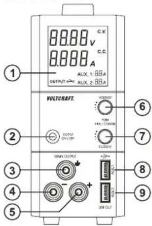
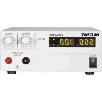
1 Display
2 Button for switching the DC outputs on and off
3 4 mm safety socket „earth potential" (mass)
4 4 mm safety socket „negative pole“ (-)
5 4 mm safety socket „positive pole“ (+)
6 Controls to adjust output voltage, VOLTAGE*
7 Controls to adjust output „CURRENT“
8 High-power USB output 1
9 High-power USB output 2
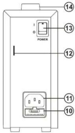
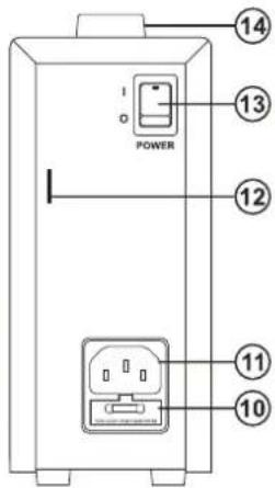
10 Mains fuse holder (rear)
11 Earthed non-heating connection (mains connection), IEC 320 C14
12 Eyelet to prevent theft, e.g., by cable lock
13 Power switch for switching the device on (1=ON / 0=OFF)
14 Carrying handle
Explanation of symbols
V
displays electrical voltage
A
displays electrical current
C.V.
display in constant voltage mode (normal mode)
C.C.
display with active current limit (constant current mode)
AUX.1
USB power output 1
AUX.2
USB power output 2
OUTPUT (ON, OFF)
OUTPUTO
Control indicator for disabled output
OUTPUT
Control indicator for enabled output
Functional Description
The DC output of the power supply unit is electrically isolated and features protective separation from the mains voltage.
A controllable low voltage protection is provided at the output. The control buttons are digitally controlled and when a button is pressed direct adjustment of the individual digits is made possible. A turn in a clockwise direction increases the adjustment value.
It is also possible to continuously adjust the current limit. A jumper at the output is not needed for the adjustment of the current. A turn in a clockwise direction increases the adjustment value.
The momentary output voltage (V) and the output current amperage (A) is shown in the display (1).
A secondary side DC connection is possible via two coloured 4mm safety sockets (4 and 5).
Two USB loads can be connected to the two high-power USB outputs AUX.1 and AUX.2, regardless of the regulated laboratory power pack.
The power supply unit is cooled passively through convection. Therefore, ensure sufficient air circulation and space on the side.

If the preset current limit is exceeded through overload or short-circuit, then this is signalled via the "C.C." display. It will electronically reduce the output voltage to avoid damage to the power supply unit.
Start-up
a) General information
- To operate the power supply unit you need a mains lead containing a protective earth wire, which is included. Use only this one or an identical mains cable. Connect the mains lead to the IEC input (11) on the rear of the power supply unit and plug the mains plug into an earthed mains socket.
- The power supply unit is not a charger. To charge batteries, use suitable chargers with a charging current cut-off.
• Always turn the device off when it is not in use.
b) Setting the output voltage
- Ensure that there are no loads connected to the mains power supply.
- Switch on the mains power supply at the power switch (13). The display is illuminated.
- Make sure that the "C.V." indicator is on. If this is not the case and indicator "C.C." is on, turn the current adjustment control "CURRENT" (7) in a clockwise direction.
- Turn the adjustment control „VOLTAGE“ (6) to roughly to the desired output voltage. Access the fine adjustment menu by briefly pressing on the control button (6). The first decimal of the voltage „V“ starts flashing. The value of this decimal can be changed by turning the control button.
- Switch to the next decimal by pressing the button again briefly. Make the adjustment until you reach the desired voltage value.
- Wait a few seconds and the laboratory power pack returns to the normal setting.
c) Setting the current limitation
- Adjust the output voltage as described above.
- Turn the adjustment control „VOLTAGE“ (7) roughly to the desired current limit. Access the fine adjustment menu by briefly pressing on the control button (7). The first decimal of the current indicator „A“ starts flashing. The value of this decimal can be changed by turning the control button.
- Switch to the next decimal by pressing the button again briefly. Make the adjustment until you reach the desired current value.
- Wait a few seconds and the laboratory power pack returns to the normal setting. The current indicator shows 0.000 A.
- To check the setting for the current, briefly press and the control button "Current" (7). The value of the current limit is briefly displayed.
- If no current limit is needed, ensure that it is always set to the highest current value so that operation of the power supply is not reduced.
d) Enabling/disabling outputs
- The adjustable output and the two USB outputs are enabled and disabled by pressing a button on the power pack.
- The status is shown by two symbols on the display: OUTPUT o → Control indicator for disabled output OUTPUT o → Control indicator for enabled output
- By briefly pressing the „OUTPUT“ button (2), you can switch the adjustable output on or off.
- By pressing on the „OUTPUT“ button (2) for approximately 3 seconds will disable all outputs (control output and 2x USB). Briefly press the „OUTPUT“ button (2) will again enable all outputs.
Connecting a consumer load

Make sure that the load is switched off when being connected to the power supply unit. If the load is switched on, it can cause sparking while connecting to the sockets. This can damage the sockets, as well as the connected cables.
- Verify that the correct output voltage has been set on the power supply unit.
- Connect the positive terminal (+) of the load with the red socket „+” (5) and the negative terminal (-) of the load with the black socket „-” (4).
- The connection is made using standard 4mm plugs. You can also use isolated laboratory plugs.
- The green earthing potential socket (3) is connected to the earthing conductor directly. The adjustable output can be used with the positive terminal to ground reference, or the negative terminal to ground reference or floating.
- Enable the output on the power pack by pressing the „OUTPUT ON / OFF* (2) button.
- Switch the consumer on. The current indicator, A" (7) displays the current that the connected load draws.
USB loads
- You can connect USB loads via the two USB sockets „AUX.1“ and „AUX.2“ regardless of the adjustable output. Note, however, the max. power consumption of the USB loads.
- You can check the current output to the USB sockets (8/9) via the indicator „AUX.1“ for USB output „AUX.1“ and the indicator „AUX.2“ for output „AUX.2“. Current is displayed in Ampere „A“.
Maintenance and Cleaning

Always unplug the power plug from the mains socket before cleaning the device.
Except for replacing the fuse and occasional cleaning, the power supply unit does not require any maintenance.
Use a dry, clean, lint-free, antistatic cloth to clean the device. Do not use any abrasive or chemical agents or detergents containing solvents.
Replacing the Fuse
- If it is no longer possible to switch on the power unit, the mains fuse is probably defective.
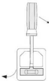
• Proceed as follows to replace the mains fuse: - Tum off the power supply unit and remove all connecting cables from the unit. Pull the mains plug from the rear connection (11).
- Remove the rear fuse holder (10) with a suitable screwdriver from the bracket, as displayed.
- Replace the defective fuse with a new fine-wire fuse (5x20 mm) of the same type and rated current: Please refer to the Technical Data or the labels on the device for the security value.
- Push the fuse carefully into the fuse holder.
natural_image
Diagram of a screwdriver with directional arrows indicating movement or force (no text or symbols)Troubleshooting
By purchasing this power supply unit you have acquired a product that has been designed to the latest state of the art and which is operationally reliable. Nevertheless, problems or faults may occur. Therefore, we would like to describe here how to eliminate possible faults:

Always observe the safety instructions!
| Problem/event Solution/explanation | |
| The display is not illuminated. No mains voltage?Check the safety switch for the mains socketCheck whether the mains plug is seated correctly in the mains socketCheck the mains fuse in the power supply unit. | |
| Connected loads don't work. Correct voltage set?Is the polarity correct?Has the power supply overloaded or is the current limitation (display "CC") active?Check the technical data of the load.Output switched off manually? | |
| There is no voltage from the power pack. | The power supply unit has overheated.Remove the load from the power pack and let the power pack cool off for at least 30 min. The power pack will automatically enable the output again once the correct operating temperatures are reached. Check the technical data. |
| The "CV" indicator is lit The power supply unit is working in the normal constant voltage mode. | |
| The "CV" indicator is lit The power supply unit is working in the normal constant voltage mode. Check the load's power consumption or increase the current limit. |

Repairs other than those described above should only be performed by an authorised specialist. Check the technical safety of the device on a regular basis e.g., for damage to the housing, etc. Any changes and repairs you make on the device will render the guarantee/warranty null and void.
Disposal

Electronic products are recyclable material and do not belong in the household waste. Dispose of an unserviceable product in accordance with the relevant statutory regulations.
Technical Data
| TOPS-3205 TOPS-3363 TOPS-3602 | |||
| Output voltage 1 - 20 V/DC 1 - 36 V/DC | 1 - 60 V/DC | ||
| Output current 0.25 – 5 A 0.25 – 3 A 0.25 – 1.6 A | |||
| Display resolution 0.01 V / 0.001 A | |||
| Display accuracy "V" | < 5 V: ±0.05 V≥ 5 V: ±(0,2% + 0.05 V) | ||
| Display accuracy "A" | ≤ 1 A: ±0.015 A> 1 A: ±(0,5% + 0.006 A) | ||
| Max. output power 100 W | |||
| Residual ripple (p-p) <120 mV <150 mV <180 mV | |||
| Control response at Change of load 10~90% | 70 mV50 mA | ||
| Control response at Mains change 10% | 25 mV20 mA | ||
| Output USB AUX 1 5 V/DC, max. 1.8 A | |||
| Output USB AUX 2 5 V/DC, max. 1.8 A | |||
| Mains fuse5x 20 mm fine fuse | T2A/250 V time lag | ||
| Operating temperature | +5 °C to +40 °C | ||
| Rel. Humidity | max. 85%, non-condensing | ||
| Max. operating altitude | 2000 m above sea level | ||
| Pollution degree | 2 | ||
| Operating voltage | 100 - 240 V AC, 50/60 Hz | ||
| Power consumption max. | 1.6 A (at 230 V ca. 0.83 A) | ||
| Protection class | 1 | ||
| Power factor (active PFC) | >0.9 | ||
| Degree of effectiveness | ≥80.5 % | ||
| Unit' cooling system | Convection | ||
| Dimensions (W x H x D) | 70 x 150 x 250 (mm) | ||
| Weight | 2 kg | ||
| LVD Directive 2006/95/EC | EN 61010 | ||
F Mode d'emploi
natural_image
Diagram of a screwdriver holding a mechanical component (no text or symbols)natural_image
Diagram of a screwdriver with directional arrows indicating movement or force (no text or symbols)


- GB Operating instructions
- TOPS-3602 100 Watt Laboratory Power Supply
- Intended Use
- Explanation of symbols
- Safety Instructions
- Package Contents
- Functional Description
- Start-up
- a) General information
- b) Setting the output voltage
- c) Setting the current limitation
- d) Enabling/disabling outputs
- Connecting a consumer load
- USB loads
- Maintenance and Cleaning
- Replacing the Fuse
- Troubleshooting
- Disposal
- F Mode d'emploi
Brand : VOLTCRAFT
Model : TOPS3363
Category : Laboratory power supply