
639121 - Electric saw MILWAUKEE - Free user manual and instructions
Find the device manual for free 639121 MILWAUKEE in PDF.
| Product Type | Circular Saw |
| Brand | Milwaukee |
| Model | 639121 |
| Supply Voltage | 120 V AC/DC |
| Rated Current | 15 A |
| No-load Speed | 6,300 RPM |
| Blade Diameter | 184 mm (7-1/4") |
| Blade Arbor | 16 mm (5/8") |
| Cutting Depth at 90° | 0 to 63 mm (0 to 2-15/32") |
| Cutting Depth at 45° | 0 to 46 mm (0 to 1-13/16") |
| Bevel Angle Range | 0° to 45° |
| Approximate Weight | 5 kg |
| Handle Type | Adjustable Tilt-Lok™ (8 positions) |
| Blade Protection | Retractable Lower Guard |
| Main Functions | Cross-cutting, ripping, bevel cutting, plunge cutting |
| Maintenance and Cleaning | Clean vents with a damp cloth and mild soap; do not use solvents |
| Safety | Disconnect before adjustments; wear eye protection; check lower guard |
| Spare Parts | Blade bolt, inner/outer flange, spindle lock button |
| Warranty | 5 years (except exceptions) |
Frequently Asked Questions - 639121 MILWAUKEE
User questions about 639121 MILWAUKEE
0 question about this device. Answer the ones you know or ask your own.
Ask a new question about this device
Download the instructions for your Electric saw in PDF format for free! Find your manual 639121 - MILWAUKEE and take your electronic device back in hand. On this page are published all the documents necessary for the use of your device. 639121 by MILWAUKEE.
USER MANUAL 639121 MILWAUKEE
Cat. No. / No de cat.
6391
HEAVY DUTY LEFT BLADE CIRCULAR SAW WITH TILT-LOK™ HANDLE
ROBUSTE SCIE CIRCULAIRE À POIGNÉE TILT-LOK™ ET LAME À GAUCHE
SIERRA CIRCULAR DE CUCHILLA IZQUIERDA PARA TRABAJO PESADO CON EMPUÑADURA TILT-LOK™ (INCLINABLE-FIJABLE)
WARNING To reduce the risk of injury, user must read and understand operator's manual.
⚠ WARNING Read all safety warnings, instructions, illustrations and specifica-
tions provided with this power tool. Failure to follow all instructions listed below may result in electric shock, fire and/or serious injury. Save all warnings and instructions for future reference. The term "power tool" in the warnings refers to your mains-operated (corded) power tool or battery-operated (cordless) power tool.
WORK AREA SAFETY
- Keep work area clean and well lit. Cluttered or dark areas invite accidents.
- Do not operate power tools in explosive atmospheres, such as in the presence of flammable liquids, gases or dust. Power tools create sparks which may ignite the dust or fumes.
- Keep children and bystanders away while operating a power tool. Distractions can cause you to lose control.
ELECTRICAL SAFETY
- Power tool plugs must match the outlet. Never modify the plug in any way. Do not use any adapter plugs with earthed (grounded) power tools. Unmodified plugs and matching outlets will reduce risk of electric shock.
- Avoid body contact with earthed or grounded surfaces, such as pipes, radiators, ranges and refrigerators. There is an increased risk of electric shock if your body is earthed or grounded.
- Do not expose power tools to rain or wet conditions. Water entering a power tool will increase the risk of electric shock.
- Do not abuse the cord. Never use the cord for carrying, pulling or unplugging the power tool. Keep cord away from heat, oil, sharp edges or moving parts. Damaged or entangled cords increase the risk of electric shock.
- When operating a power tool outdoors, use an extension cord suitable for outdoor use. Use of a cord suitable for outdoor use reduces the risk of electric shock.
- If operating a power tool in a damp location is unavoidable, use a ground fault circuit interrupter (GFCI) protected supply. Use of an GFCI reduces the risk of electric shock.
PERSONAL SAFETY
- Stay alert, watch what you are doing and use common sense when operating a power tool. Do not use a power tool while you are tired or under the influence of drugs, alcohol or medication. A moment of inattention while operating power tools may result in serious personal injury.
- Use personal protective equipment. Always wear eye protection. Protective equipment such as a dust mask, non-skid safety shoes, hard hat or hearing protection used for appropriate conditions will reduce personal injuries.
-
Prevent unintentional starting. Ensure the switch is in the off-position before connecting to power source and/or battery pack, picking up or carrying the tool. Carrying power tools with your finger on the switch or energizing power tools that have the switch on invites accidents.
-
Remove any adjusting key or wrench before turning the power tool on. A wrench or a key left attached to a rotating part of the power tool may result in personal injury.
- Do not overreach. Keep proper footing and balance at all times. This enables better control of the power tool in unexpected situations.
- Dress properly. Do not wear loose clothing or jewelry. Keep your hair and clothing away from moving parts. Loose clothes, jewelry or long hair can be caught in moving parts.
- If devices are provided for the connection of dust extraction and collection facilities, ensure these are connected and properly used. Use of dust collection can reduce dust-related hazards.
- Do not let familiarity gained from frequent use of tools allow you to become complacent and ignore tool safety principles. A careless action can cause severe injury within a fraction of a second.
POWER TOOL USE AND CARE
- Do not force the power tool. Use the correct power tool for your application. The correct power tool will do the job better and safer at the rate for which it was designed.
- Do not use the power tool if the switch does not turn it on and off. Any power tool that cannot be controlled with the switch is dangerous and must be repaired.
- Disconnect the plug from the power source and/or remove the battery pack, if detachable, from the power tool before making any adjustments, changing accessories, or storing power tools. Such preventive safety measures reduce the risk of starting the power tool accidentally.
- Store idle power tools out of the reach of children and do not allow persons unfamiliar with the power tool or these instructions to operate the power tool. Power tools are dangerous in the hands of untrained users.
- Maintain power tools and accessories. Check for misalignment or binding of moving parts, breakage of parts and any other condition that may affect the power tool's operation. If damaged, have the power tool repaired before use. Many accidents are caused by poorly maintained power tools.
- Keep cutting tools sharp and clean. Properly maintained cutting tools with sharp cutting edges are less likely to bind and are easier to control.
- Use the power tool, accessories and tool bits etc. in accordance with these instructions, taking into account the working conditions and the work to be performed. Use of the power tool for operations different from those intended could result in a hazardous situation.
- Keep handles and grasping surfaces dry, clean and free from oil and grease. Slippery handles and grasping surfaces do not allow for safe handling and control of the tool in unexpected situations.
SERVICE
- Have your power tool serviced by a qualified repair person using only identical replacement parts. This will ensure that the safety of the power tool is maintained.
SPECIFIC SAFETY RULES FOR LEFT BLADE CIRCULAR SAWS
Cutting procedures
DANGER
Keep hands away from cutting area and the blade. Keep your second
hand on auxiliary handle, or motor housing. If both hands are holding the saw, they cannot be cut by the blade.
- Do not reach underneath the workpiece. The guard cannot protect you from the blade below the workpiece.
- Adjust the cutting depth to the thickness of the workpiece. Less than a full tooth of the blade teeth should be visible below the workpiece.
- Never hold the workpiece in your hands or across your leg while cutting. Secure the workpiece to a stable platform. It is important to support the work properly to minimise body exposure, blade binding, or loss of control.
- Hold the power tool by insulated gripping surfaces only, when performing an operation where the cutting tool may contact hidden wiring or its own cord. Contact with a "live" wire will also make exposed metal parts of the power tool "live" and could give the operator an electric shock.
- When ripping, always use a rip fence or straight edge guide. This improves the accuracy of cut and reduces the chance of blade binding.
- Always use blades with correct size and shape (diamond versus round) of arbour holes. Blades that do not match the mounting hardware of the saw will run off-centre, causing loss of control.
- Never use damaged or incorrect blade washers or bolt. The blade washers and bolt were specially designed for your saw, for optimum performance and safety of operation.
Further safety instructions for all saws Kickback causes and related warnings
- Kickback is a sudden reaction to a pinched, jammed or misaligned saw blade, causing an uncontrolled saw to lift up and out of the workpiece toward the operator;
- When the blade is pinched or jammed by the kerf closing down, the blade stalls and the motor reaction drives the unit rapidly back toward the operator;
- If the blade becomes twisted or misaligned in the cut, the teeth at the back edge of the blade can dig into the top surface of the wood causing the blade to climb out of the kerf and jump back toward the operator.
Kickback is the result of saw misuse and/or incorrect operating procedures or conditions and can be avoided by taking proper precautions as given below:
- Maintain a firm grip with both hands on the saw and position your arms to resist kickback forces. Position your body to either side of the blade, but not in line with the blade. Kickback could cause the saw to jump backwards, but kickback forces can be controlled by the operator, if proper precautions are taken.
- When blade is binding, or when interrupting a cut for any reason, release the trigger and hold the saw motionless in the material until the blade comes to a complete stop. Never attempt to remove the saw from the work or pull the saw backward while the blade is in motion or kick-
back may occur. Investigate and take corrective actions to eliminate the cause of blade binding.
- When restarting a saw in the workpiece, centre the saw blade in the kerf so that saw teeth are not engaged into the material. If saw blade binds, it may walk up or kickback from the workpiece as the saw is restarted.
- Support large panels to minimise the risk of blade pinching and kickback. Large panels tend to sag under their own weight. Supports must be placed under the panel on both sides, near the line of cut and near the edge of the panel.
- Do not use dull or damaged blades. Unsharpened or improperly set blades produce narrow kerf causing excessive friction, blade binding and kickback.
- Blade depth and bevel adjusting locking levers must be tight and secure before making cut. If blade adjustment shifts while cutting, it may cause binding and kickback.
- Use extra caution when sawing into existing walls or other blind areas. The protruding blade may cut objects that can cause kickback.
Lower guard function
- Check lower guard for proper closing before each use. Do not operate the saw if lower guard does not move freely and close instantly. Never clamp or tie the lower guard into the open position. If saw is accidentally dropped, lower guard may be bent. Raise the lower guard with the retracting handle and make sure it moves freely and does not touch the blade or any other part, in all angles and depths of cut.
- Check the operation of the lower guard spring. If the guard and the spring are not operating properly, they must be serviced before use. Lower guard may operate sluggishly due to damaged parts, gummy deposits, or a build-up of debris.
- The lower guard may be retracted manually only for special cuts such as “plunge cuts” and “compound cuts”. Raise the lower guard by the retracting handle and as soon as the blade enters the material, the lower guard must be released. For all other sawing, the lower guard should operate automatically.
• Always observe that the lower guard is covering the blade before placing saw down on bench or floor. An unprotected, coasting blade will cause the saw to walk backwards, cutting whatever is in its path. Be aware of the time it takes for the blade to stop after switch is released.
WARNING To reduce the risk of injury in applications that produce a considerable amount of dust, use an OSHA compliant dust extraction solution in accordance with the solution's operating instructions.
- Always use common sense and be cautious when using tools. It is not possible to anticipate every situation that could result in a dangerous outcome. Do not use this tool if you do not understand these operating instructions or you feel the work is beyond your capability; contact Milwaukee Tool or a trained professional for additional information or training.
- Maintain labels and nameplates. These carry important information. If unreadable or missing, contact a MILWAUKEE service facility for a free replacement.
- AWARNING Some dust created by power sanding, sawing, grinding, drilling, and other construction activities contains chemicals known to cause cancer, birth defects or other reproductive harm. Some examples of these chemicals are:
- lead from lead-based paint
•crystalline silica from bricks and cement and other masonry products, and
•arsenic and chromium from chemically-treated lumber.
Your risk from these exposures varies, depending on how often you do this type of work. To reduce your exposure to these chemicals: work in a well ventilated area, and work with approved safety equipment, such as those dust masks that are specially designed to filter out microscopic particles.
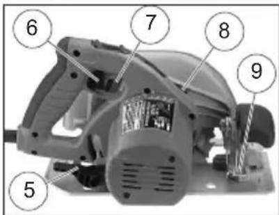
FUNCTIONAL DESCRIPTION
- Handle release lever
- Handle lever release button
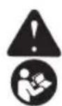
- Bevel scale
- Bevel pointer
- Depth adjusting lever
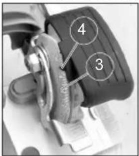
- Trigger
- Depth setting gauge (not shown)
- Spindle lock button
- Bevel adjusting lever
- Tilt-Lok ^TM handle
- Upper guard
- Lower guard lever
- Blade
- Shoe
- Lower guard
- Blade bolt
- Outer blade flange
- Inner flange (not shown)
- Sight line
- Rip fence slot
- Front handle

SYMBOLOGY


Alternating Current/Direct Current

n_0 KIXKoxid ^1 Revolutions per Minute (RPM)
cULus UL Listing for Canada and U.S.
SPECIFICATIONS
Cat. No....6391
Volts 120 AC/DC
Amps 15
No Load RPM 6300
Blade Size. 7-1/4"
Arbor 5/8"
Depth of Cut at 90°....0 to 2-15/32"
Depth of Cut at 45°....0 to 1-13/16"
EXTENSION CORDS
Grounded tools require a three wire extension cord. Double insulated tools can use either a two or three wire extension cord. As the distance from the supply outlet increases, you must use a heavier gauge extension cord. Using extension cords with inadequately sized wire causes a serious drop in voltage, resulting in loss of power and possible tool damage. Refer to the table shown to determine the required minimum wire size.
The smaller the gauge number of the wire, the greater the capacity of the cord. For example, a 14 gauge cord can carry a higher current than a 16 gauge cord. When using more than one extension cord to make up the total length, be sure each cord contains at least the minimum wire size required. If you are using one extension cord for more than one tool, add the nameplate amperes and use the sum to determine the required minimum wire size.
Guidelines for Using Extension Cords
- If you are using an extension cord outdoors, be sure it is marked with the suffix "W-A" ("W" in Canada) to indicate that it is acceptable for outdoor use.
- Be sure your extension cord is properly wired and in good electrical condition. Always replace a damaged extension cord or have it repaired by a qualified person before using it.
- Protect your extension cords from sharp objects, excessive heat and damp or wet areas.
| Recommended Minimum Wire Gauge For Extension Cords* | |||||
| Nameplate Amps | Extension Cord Length | ||||
| 25' 50' 75' | 100' | 150' | |||
| 0 - 2.0 | 18 | 18 | 18 | 18 | 16 |
| 2.1 - 3.4 | 18 | 18 | 18 | 16 | 14 |
| 3.5 - 5.0 | 18 | 18 | 16 | 14 | 12 |
| 5.1 - 7.0 | 18 | 16 | 14 | 12 | 12 |
| 7.1 - 12.0 | 16 | 14 | 12 | 10 | -- |
| 12.1 - 16.0 | 14 | 12 | 10 | -- | -- |
| 16.1 - 20.0 | 12 | 10 | -- | -- | -- |
* Based on limiting the line voltage drop to five volts at 150% of the rated amperes.
READ AND SAVE ALL INSTRUCTIONS FOR FUTURE USE.
GROUNDING
WARNING
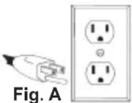
Improperly connecting the ground- ing wire can result in the risk of electric shock. Check with a qualified electrician if you are in doubt as to whether the outlet properly grounded. Do not modify the plug provided with the tool. Never remove the grounding prong from the plug. Do not use the tool if the cord or plug is damaged. If damaged, have it repaired by a MILWAUKEE service facility before use. If the plug will not fit the outlet, have proper outlet installed by a qualified electrician.
Grounded Tools (Three-Prong Plugs)
Tools marked “Grounding Required” have a three wire cord and three prong grounding plug. The plug must be connected to a properly grounded outlet (See Figure A). If the tool should electrically malfunction or break down, grounding provides a low resistance path to carry electricity away from the user, reducing the risk of electric shock.
The grounding prong in the plug is connected through the green wire inside the cord to the grounding system in the tool. The green wire in the cord must be the only wire connected to the tool's grounding system and must never be attached to an electrically "live" terminal.
Your tool must be plugged into an appropriate outlet, properly installed and grounded in accordance with all codes and ordinances. The plug and outlet should look like those in Figure A.
Double Insulated Tools (Two-Prong Plugs)
Tools marked "Double Insulated" do not require grounding. They have a special double insulation system which satisfies OSHA requirements and complies with the applicable standards of Underwriters Laboratories, Inc., the Canadian Standard Association and the National Electrical Code. Double Insulated tools may be used in either of the 120 volt outlets shown in Figures B and C.
ASSEMBLY
WARNING
To reduce the risk of injury, always unplug tool before changing or removing accessories. Only use accessories specifically recommended for this tool. Others may be hazardous.
Only use accessories with maximum speed rating at least as high as nameplate RPM of tool.
Selecting Blade
Select a blade appropriate for your application. Refer to the "Accessories" section for a list of blades to be used for the proper applications of this tool. Always use sharp blades. Dull blades tend to overload the tool and increase the chance of KICKBACK. Only use thin kerf blades with a maximum safe operating speed greater than the no load RPM marked on the tool's nameplate. Read the blade manufacturer's instructions before use. Do not use any type of abrasive cut-off wheel or dry diamond cutting blades. Use the correct blade type for your application. Using the wrong blade may result in reduced performance or damage to the blade. Do not use blades that are cracked or have broken teeth. Do not sharpen ferrous metal cutting blades; see the blade manufacturer's recommendations regarding sharpening.

Rip & Crosscut
A multi-purpose blade for ripping, cross cutting and mitering in hardwoods, softwoods, plywood and composition materials.
is

Framing-Rip
Designed for fast and accurate ripping along the grain in hard-or softwoods where a smooth cross cut is not necessary.

Plywood-Veneer
Recommended for cutting plywood, composition materials and all types of wood where a slightly smoother finish is needed.

Finish & Trim
Especially designed for cross cutting and mitering in materials where a very smooth cut is necessary. Also cuts aluminum.
Checking the Operation of the Lower Guard
Check the operation and condition of the lower guard lever. If the guard and the lever are not operating properly, they must be serviced before use. Lower guard may operate sluggishly due to damaged parts, gummy deposits, or a buildup of debris.
- Unplug tool before checking the lower guard.
- Place the tool on its side.
NOTE: This procedure will not show proper lower guard operation if the tool is not on its side.
- Grasp the lower guard by the sides and push it all the way back into the blade housing.
- Release the lower guard.
- If the guard immediately springs back into place, it is working correctly and you may continue with use.
- If the guard does not immediate spring back into place, clean the upper and lower guards to remove all chips and debris. Then, check the operation again by starting with step 1.
- If the guard still does not immediately spring back into place, contact a MILWAUKEE service facility for repairs.
Installing and Removing Blades
- Unplug tool before installing or removing blades.
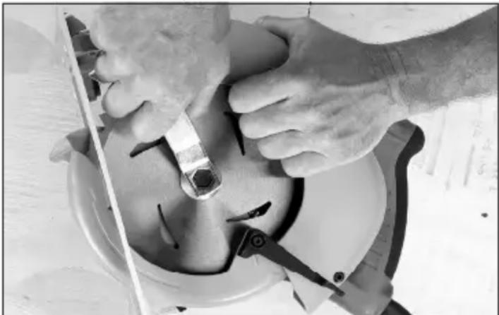
- Place the saw on a flat surface with the blade facing upwards. To remove the bolt from the spindle, push in the spindle lock button. While holding the spindle lock button in, use the wrench provided with the tool to turn the bolt clockwise. Remove the bolt and outer blade flange. Do not remove inner blade flange.
natural_image
Close-up of hands using a tool to adjust or install a mechanical component, no visible text or symbols-
Slide the lower guard lever up to raise the lower guard. Remove the blade from the spindle. Always clean the spindle, upper guard and lower guard to remove any dirt and sawdust.
-
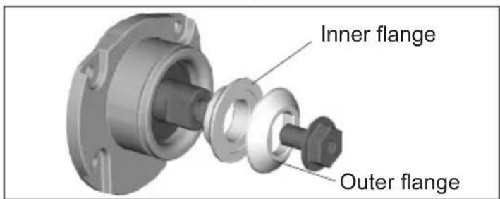
To install a blade, place the blade on the spindle with the teeth pointing in the same direction as the arrow on the lower guard. Larger diameter of inner flange should rest on blade. Release the lower guard lever.
-
Place the outer blade flange on the spindle and hand tighten the bolt. Larger diameter of outer flange should rest on blade.
-
While holding the spindle lock button in, use the wrench to turn the bolt counterclockwise and tighten.
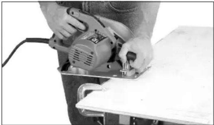
Adjusting Depth
- Unplug tool.
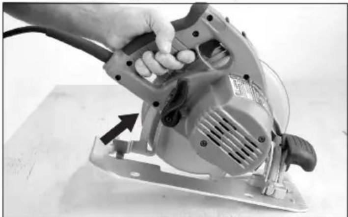
- To adjust the depth of the cut, hold the saw by the Tilt-Lok™ handle and loosen the depth adjusting lever by lifting it up and away from the shoe.
natural_image
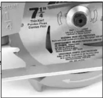
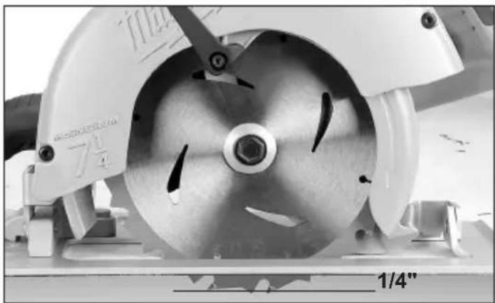
Close-up of a hand using a power tool on a cutting board, with an arrow indicating the blade direction (no visible text or symbols)- Raise or lower the shoe to the desired position. Markings in 1/4" increments are located on the inner side of the upper guard for depth setting. For the proper depth setting, the blade should extend no more than 1/4" below the material being cut.
natural_image
Close-up of a mechanical cutting tool with a 7¼" flange and a 1/4" scale indicator (no text or symbols on the tool itself)- Move the depth adjusting lever towards the shoe and push down to secure the position.
Adjusting Bevel Angle
- Unplug tool.
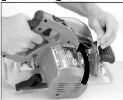
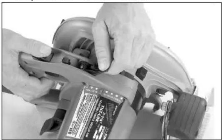
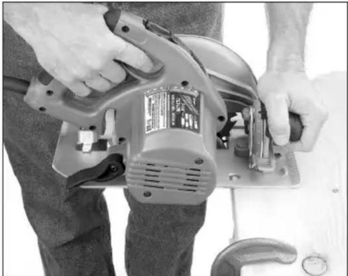
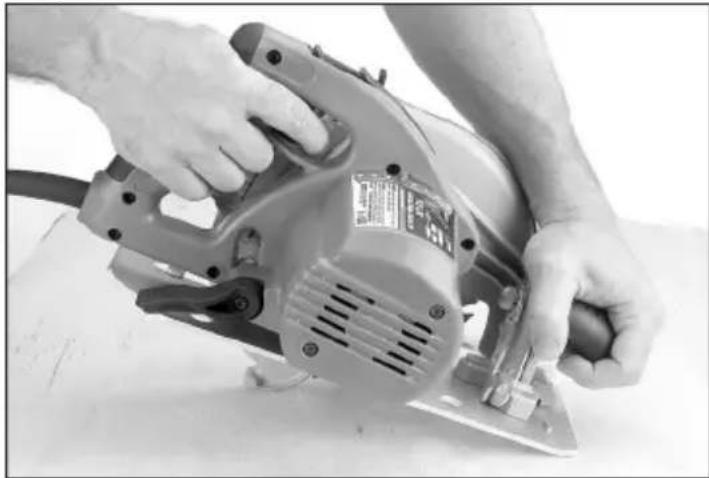
- To adjust the angle of the cut, hold the saw by the Tilt-Lok™ handle and loosen the bevel adjusting lever by lifting it up towards the blade.
- Hold the front handle and rotate the saw by the Tilt-Lok handle to the desired angle as indicated by the markings on the bevel scale.
- Move the bevel adjusting lever away from the blade and push down to secure the position.
natural_image
Close-up of hands operating a sewing machine with a black plastic sleeve (no visible text or symbols)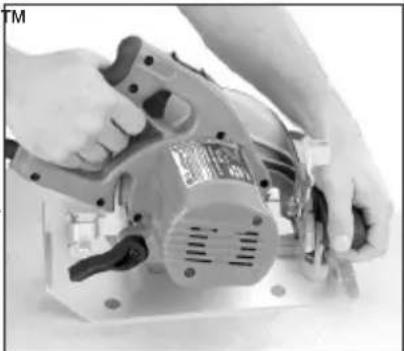
natural_image
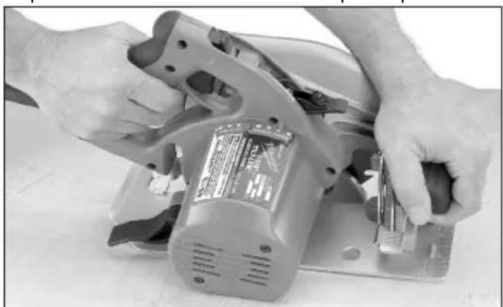
Close-up of hands operating a mechanical power supply or motor with no visible text or symbolsAdjusting Tilt-Lok™ Handle Angle
This circular saw is equipped with an adjustable handle. The Tilt-Lok™ feature allows the user to adjust the angle of the handle for optimum cutting positions.
- Unplug tool.
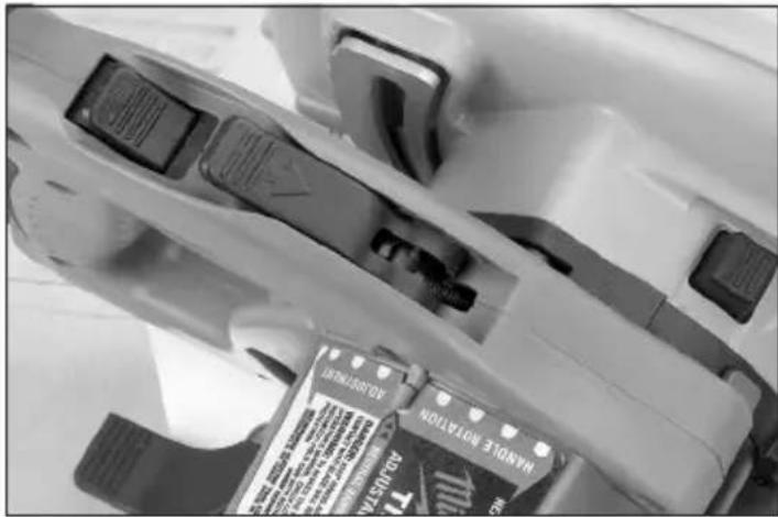
- Press in and hold the handle lever release button.
- Loosen the handle release lever by lifting it up and away from the Tilt-Lok™ handle.
natural_image
Close-up of hands operating a power tool with a label on the blade (no visible text or symbols)- To adjust the handle position, hold the front handle and rotate the Tilt-Lok™ handle to the desired angle as indicated by the handle rotation adjustment markings. The Tilt-Lok™ feature has eight (8) detents which allow the handle to snap into position. Allow the detent to snap into place.
natural_image
Close-up of hands operating a power tool on a cutting board (no visible text or symbols)NOTE: The blade depth setting will determine the range of Tilt-Lok™ positions available for the application. See “Adjusting Depth” for instructions on adjusting the blade depth.
- Push the handle release lever back into the handle until it snaps into place.
NOTE: The saw will not operate if the handle release lever is not properly secured.
AWARNING Do not operate saw with handle lever release button pressed in or with handle not locked into position.
If the Tilt-Lok™ handle moves with the handle release lever in the locked position, do not operate saw. Return the circular saw to a MILWAUKEE service facility for repair immediately.
Adjusting the Blade to Shoe
The shoe has been adjusted at the factory to a 90^ setting. Inspect the saw regularly to make sure the blade is 90^ to the shoe.
- Unplug tool.
- Set the bevel pointer to zero.
- To make sure the blade is 90^ to the shoe, place saw on the blade side and retract lower guard. Place a square against the blade and shoe to inspect the degree setting.
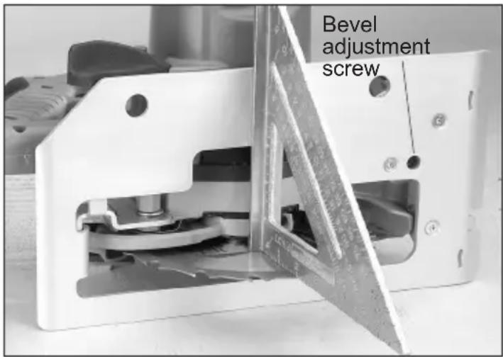
- To adjust the degree setting, loosen the bevel adjusting lever up by lifting it up towards the blade. Turn the bevel adjustment screw in or out until the blade is at a 90° angle with the shoe.
- Check that the bevel pointer is at 0^ . To adjust the bevel pointer, loosen the two screws in the front handle and reposition the bevel pointer to 0^ .
OPERATION
AWARNING To reduce the risk of injury, always wear proper eye protection marked to comply with ANSI Z87.1.
When working in dusty situations, wear appropriate respiratory protection or use an OSHA compliant dust extraction solution.
Always unplug tool before attaching or removing accessories or making adjustments. Use only specifically recommended accessories. Others may be hazardous.
Further safety instructions for all saws Kickback causes and related warnings
- Kickback is a sudden reaction to a pinched, bound or misaligned saw blade, causing an uncontrolled saw to lift up and out of the workpiece toward the operator;
- When the blade is pinched or bound tightly by the kerf closing down, the blade stalls and the motor reaction drives the unit rapidly back toward the operator;
If the blade becomes twisted or misaligned in the cut, the teeth at the back edge of the blade can dig into the top surface of the wood causing the blade to climb out of the kerf and jump back toward the operator.
Kickback is the result of saw misuse and/or incorrect operating procedures or conditions and can be avoided by taking proper precautions as given below:
- Maintain a firm grip with both hands on the saw and position your arms to resist kickback forces. Position your body to either side of the blade, but not in line with the blade. Kickback could cause the saw to jump backwards, but kickback forces can be controlled by the operator, if proper precautions are taken.
- When blade is binding, or when interrupting a cut for any reason, release the trigger and hold the saw motionless in the material until the blade comes to a complete stop. Never attempt to remove the saw from the work or pull the saw backward while the blade is in motion or kick-back may occur. Investigate and take corrective actions to eliminate the cause of blade binding.
- When restarting a saw in the workpiece, centre the saw blade in the kerf and check that saw teeth are not engaged into the material. If saw blade is binding, it may walk up or kickback from the workpiece as the saw is restarted.
- Support large panels to minimise the risk of blade pinching and kickback. Large panels tend to sag under their own weight. Supports must be placed under the panel on both sides, near the line of cut and near the edge of the panel.
- Do not use dull or damaged blades. Unsharpened or improperly set blades produce narrow kerf causing excessive friction, blade binding and kickback.
- Blade depth and bevel adjusting locking levers must be tight and secure before making cut. If blade adjustment shifts while cutting, it may cause binding and kickback.
- Use extra caution when sawing into existing walls or other blind areas. The protruding blade may cut objects that can cause kickback.
General Operation
Always clamp the workpiece securely on a saw horse or bench. See "APPLICATIONS" for the correct way to support your work in different situations.
natural_image
Person using a power tool on a cutting board (no visible text or symbols)- Draw a cutting line. Place the front of the shoe on the edge of the workpiece without making blade contact. Hold the Tilt-Lok™ handle with one hand and the front handle with the other.
natural_image
Person using a power tool on a workbench, no visible text or symbols- Line up the sight line with your cutting line. Position your arms and body to resist KICKBACK. Pull the trigger, allowing the motor to reach full speed before beginning to cut.
- While cutting, keep the shoe flat against the workpiece and maintain a firm grip. Do not force the saw through the workpiece. Forcing a saw can cause KICKBACK.
- If making a partial cut, restarting in mid-cut or correcting direction, allow the blade to come to a complete stop. To resume cutting, center the blade in the kerf, back the saw away from cutting edge a few inches, pull the trigger and re-enter the cut slowly.
- If the saw binds and stalls, maintain a firm grip and release the trigger immediately. Hold the saw motionless in the workpiece until the blade comes to a complete stop.
- After finishing a cut, be sure the lower guard closes and the blade comes to a complete stop before setting the saw down.
Troubleshooting
If the blade does not follow a straight line:
- Teeth are dull. This is caused by hitting a hard object such as a nail or stone, dulling teeth on one side. The blade tends to cut to the side with the sharpest teeth.
- Shoe is out of line or bent
- Blade is bent
- Rip fence or guide is not being used If the blade binds, smokes or turns blue from friction:
- Blade is dull
- Blade is on backwards
- Blade is bent
- Blade is dirty
• Workpiece is not properly supported - Incorrect blade is being used
APPLICATIONS
AWARNING To reduce the risk of injury, always unplug tool before attaching or removing accessories or making adjustments. Use only specifically recommended accessories. Others may be hazardous.
Always wear proper eye protection marked to comply with ANSI Z87.1.
Selecting Tilt-Lok™ Handle Positions
The Tilt-Lok™ handle is a feature which allows the user to adjust the angle of the handle for optimum cutting positions. The Tilt-Lok™ handle has eight (8) detents which allow the handle to snap into position. See “Adjusting Tilt-Lok™ Handle” for instructions on adjusting the handle. Refer to the chart below for suggested handle positions.
* These are only suggested positions; the actual optimum cutting position may vary depending on the actual application and user preference.
| APPLICATION | SUGGESTED TILT-LOKTM POSITIONS* |
| For cuts made at or near waist level | Handle in lower positions allows for more leverage when pushing the saw through the workpiece. |
| For shallow cuts made at or near waist level | Handle in lower positions allows the user to apply increased downward force during shallow cuts. |
| For cuts made below the waist, as in flooring applications | Handle in higher positions reduce the amount of “bending over” by the user. Higher handle positions allow the user to apply an increased downward force on the saw. |
| For cuts made overhead, as in ceiling applications | Handle in higher positions reduce the amount of extended reach by the user for overhead cuts. Higher handle positions allow the user to apply an increased upward force on the saw. |
natural_image
Close-up of a mechanical component with attached adhesive tape (no visible text or symbols)
natural_image
Close-up of hands operating a power tool on a flatbed surface (no visible text or symbols)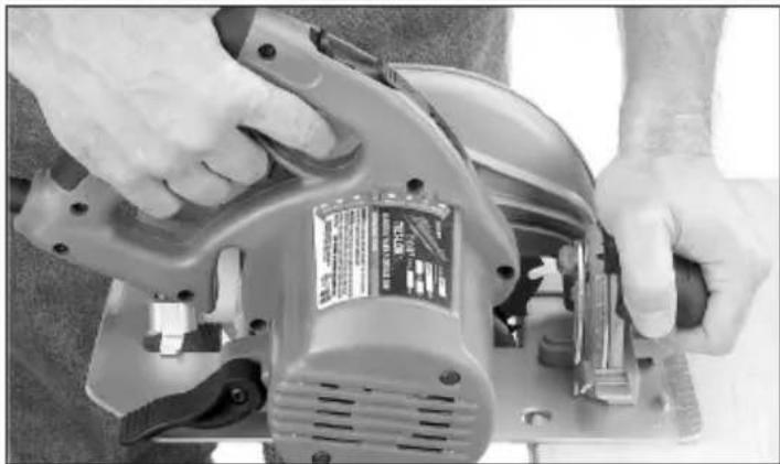
natural_image
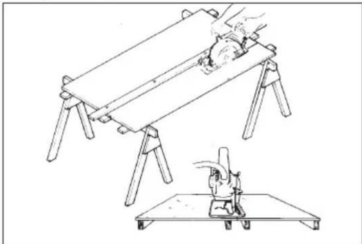
Close-up of hands operating a power tool on a cutting board (no visible text or symbols)Cutting Large Panels
Large panels and long boards sag or bend if they are not correctly supported. If you attempt to cut without leveling and properly supporting the workpiece, the blade will tend to bind, causing KICKBACK. Support large panels. Be sure to set the depth of the cut so that you only cut through the workpiece, not through the supports.
natural_image
Line drawing of a mechanical setup with a hand operating a workbench and a cutting tool on a flat base (no text or symbols)Ripping Wood
Ripping is cutting lengthwise with the grain. Select the proper blade for your job. Use a rip fence for rips 4" wide or less. To install the rip fence, slide the bar through the rip fence slot in either side of the shoe. The width of the cut is the distance from the inside of the blade to the inside edge of the rip fence. Adjust the rip fence for the desired width, and lock the setting by tightening the rip fence screws. When ripping widths greater than 4", clamp or tack 1" lumber to workpiece and use the inside edge of the shoe as a guide.
Cross-Cutting Wood
Cross-cutting is cutting across the grain. Select the proper blade for your job. Advance the saw slowly to avoid splintering the wood.
⚠ WARNING To reduce the risk of electric shock, check work area for hidden pipes and wires before making pocket cuts.
Pocket Cutting
Pocket cuts are made in the middle of the workpiece when it can not be cut from an edge. We recommend using a Sawzall® reciprocating saw or jig saw for this type of cut. However, if you must use a circular saw to make a pocket cut, USE EXTREME CAUTION. To maintain control of the saw during pocket cutting, keep both hands on the saw.
natural_image
Person using a power tool on a workbench, no visible text or symbols- Beginning at a corner, line up the sight line with your cutting line. Tilt the saw forward, firmly fixing the front of the shoe on the workpiece. The blade should be just above cutting line, but not touching it. Raise the lower guard using the lower guard lever.
- Pull the trigger, allowing the blade to come up to full speed. Using the front of the shoe as a hinge point, gradually lower the back end of the saw into the workpiece.
- When the shoe rests flat against workpiece, release the lower guard lever. Advance the saw to the far corner. Release the trigger and allow the blade to come to a complete stop before removing it from workpiece. Repeat the above steps for each side of the opening. Use a Sawzal® reciprocating saw, jig saw or small hand saw to finish the corners if they are not completely cut through.
Cutting Masonry and Metal
MILWAUKEE circular saws are not intended for continuous use in cutting metal or masonry. When cutting these materials, use the correct blade. MILWAUKEE does not recommend using bonded abrasive wheels on circular saws for any application.
AWARNING Dust, chips, and grit can cause guard to hang up at any time. If saw is used to cut masonry or metal, reserve and mark it for that purpose only and return it to a MILWAUKEE service facility for cleaning and testing before using it for wood cutting.
Only use accessories with maximum speed rating at least as high as nameplate RPM of tool.
When cutting masonry, use a diamond blade. Make successive passes at depths of less than 1/4" to achieve the desired depth. Cutting at a depth of more than 1/4" will damage wheel. Unplug the tool and frequently clean dust from air vents and guards.
AWARNING Do not use tool for cutting metal near flammable material. Sparks may cause fire.
When cutting metal, use a metal cutting blade. Set depth of cut to full depth. Protect everyone in the area from sparks
MAINTENANCE
AWARNING To reduce the risk of injury, always unplug the tool before performing any maintenance. Never disassemble the tool. Contact a MILWAUKEE service facility for ALL repairs.
Maintaining Tools
Keep your tool in good repair by adopting a regular maintenance program. Inspect your tool for issues such as undue noise, misalignment or binding of moving parts, breakage of parts, or any other condition that may affect the tool operation. Return the tool to a MILWAUKEE service facility for repair. After six months to one year, depending on use, return the tool to a MILWAUKEE service facility for inspection.
⚠ WARNING To reduce the risk of personal in-jury, electric shock and damage, never immerse your tool in liquid or allow a liquid to flow inside it.
Cleaning
Clean dust and debris from vents. Keep handles clean, dry and free of oil or grease. Use only mild soap and a damp cloth to clean, since certain cleaning agents and solvents are harmful to plastics and other insulated parts. Some of these include gasoline, turpentine, lacquer thinner, paint thinner, chlorinated cleaning solvents, ammonia and household detergents containing ammonia. Never use flammable or combustible solvents around tools.
Repairs
For repairs, return the tool to the nearest service center
ACCESSORIES
WARNING Use only recommended accessories. Others may be hazardous.
For a complete listing of accessories, go online to www.milwaukeeetool.com or contact a distributor.
SERVICE - UNITED STATES
1-800-SAWDUST (1.800.729.3878)
Monday-Friday, 7:00 AM - 6:30 PM CST or visit www.milwaukeetool.com
Contact Corporate After Sales Service Technical Support with technical, service/repair, or warranty questions.
Email: metproductsupport@milwaukeeetool.com
Become a Heavy Duty Club Member at www.milwaukeeetool.com to receive important notifications regarding your tool purchases.
SERVICE - CANADA
Milwaukee Tool (Canada) Ltd 1.800.268.4015
Monday-Friday, 7:00 AM - 4:30 PM CST or visit www.milwaukeeetool.ca
LIMITED WARRANTY USA & CANADA
Every MILWAUKEE power tool* (see exceptions below) is warranted to the original purchaser only to be free from defects in material and workmanship. Subject to certain exceptions, MILWAUKEE will repair or replace any part on an electric power tool which, after examination, is determined by MILWAUKEE to be defective in material or workmanship for a period of five (5) years** after the date of purchase unless otherwise noted. Return of the power tool to a MILWAUKEE factory Service Center location or MILWAUKEE Authorized Service Station, freight prepaid and insured, is required. A copy of the proof of purchase should be included with the return product. This warranty does not apply to damage that MILWAUKEE determines to be from repairs made or attempted by anyone other than MILWAUKEE authorized personnel, misuse, alterations, abuse, normal wear and tear, lack of maintenance, or accidents. Normal Wear: Many power tools need periodic parts replacement and service to achieve best performance. This warranty does not cover repair when normal use has exhausted the life of a part including, but not limited to, chucks, brushes, cords, saw shoes, blade clamps, o-rings, seals, bumpers, driver blades, pistons, strikers, lifters, and bumper cover washers. *This warranty does not cover Air Nailers & Staplers; Airless Paint Sprayer; Cordless Battery Packs; Gasoline Driven Portable Power Generators; Hand Tools; Hoist – Electric, Lever & Hand Chain; M12™ Heated Gear; Reconditioned Product; and Test & Measurement Products. There are separate and distinct warranties available for these products. **The warranty period for Job Site Radios, M12™ Power Port, M18™ Power Source, Jobsite Fan and Trade Titan™ Industrial Work Carts is one (1) year from the date of purchase. The warranty period for the Drain Cleaning Cables is two (2) years from the date of purchase. The warranty period for the M18™ Compact Heat Gun and the 8 Gallon Dust Extractor is three (3) years from the date of purchase. The warranty period for the LED in the LED Work Light and the LED Upgrade Bulb for the Work Light is the lifetime of the product subject to the limitations above. If during normal use the LED or LED Bulb fails, the part will be replaced free of charge.
Warranty Registration is not necessary to obtain the applicable warranty Son a MILWAUKEE power tool product. The manufacturing date of the product will be used to determine the warranty period if no proof of purchase is provided at the time warranty service is requested. ACCEPTANCE OF THE EXCLUSIVE REPAIR AND REPLACEMENT REMEDIES DESCRIBED HEREIN IS A CONDITION OF THE CONTRACT FOR THE PURCHASE OF EVERY MILWAUKEE PRODUCT. IF YOU DO NOT AGREE TO THIS CONDITION, YOU SHOULD NOT PURCHASE THE PRODUCT. IN NO EVENT SHALL MILWAUKEE BE LIABLE FOR ANY INCIDENTAL, SPECIAL, CONSEQUENTIAL OR PUNITIVE DAMAGES, OR FOR ANY COSTS, ATTORNEY FEES, EXPENSES, LOSSES OR DELAYS ALLEGED TO BE AS A CONSEQUENCE OF ANY DAMAGE TO, FAILURE OF, OR DEFECT IN ANY PRODUCT INCLUDING, BUT NOT LIMITED TO, ANY CLAIMS FOR LOSS OF PROFITS. SOME STATES DO NOT ALLOW THE EXCLUSION OR LIMITATION OF INCIDENTAL OR CONSEQUENTIAL DAMAGES, SO THE ABOVE LIMITATION OR EXCLUSION MAY NOT APPLY TO YOU. THIS WARRANTY IS EXCLUSIVE AND IN LIEU OF ALL OTHER EXPRESS WARRANTIES, WRITTEN OR ORAL. TO THE EXTENT PERMITTED BY LAW, MILWAUKEE DISCLAIMS ANY IMPLIED WARRANTIES, INCLUDING WITHOUT LIMITATION ANY IMPLIED WARRANTY OF MERCHANTABILITY OR FITNESS FOR A PARTICULAR USE OR PURPOSE; TO THE EXTENT SUCH DISCLAIMER IS NOT PERMITTED BY LAW, SUCH IMPLIED WARRANTIES ARE LIMITED TO THE DURATION OF THE APPLICABLE EXPRESS WARRANTY AS DESCRIBED ABOVE. SOME STATES DO NOT ALLOW LIMITATIONS ON HOW LONG AN IMPLIED WARRANTY LASTS, SO THE ABOVE LIMITATION MAY NOT APPLY TO YOU, THIS WARRANTY GIVES YOU SPECIFIC LEGAL RIGHTS, AND YOU MAY ALSO HAVE OTHER RIGHTS WHICH VARY FROM STATE TO STATE.
This warranty applies to product sold in the U.S.A. and Canada only. Please consult the 'Service Center Search' in the Parts & Service section of MILWAUKEE's website www.milwaukeeetool.com or call 1.800.SAWDUST (1.800.729.3878) to locate your nearest service facility for warranty and non-warranty service on a Milwaukee electric power tool.
LIMITED WARRANTY - MEXICO, CENTRAL AMERICA & CARIBBEAN
TECHTRONIC INDUSTRIES' warranty is for 5 years since the original purchase date.
This warranty card covers any defect in material and workmanship on this Product.
To make this warranty valid, present this warranty card, sealed/stamped by the distributor or store where you purchased the product, to the Authorized Service Center (ASC). Or, if this card has not been sealed/stamped, present the original proof of purchase to the ASC. Call 55 4160-3547 to find the nearest ASC, for service, parts, accessories or components.
Procedure to make this warranty valid
Take the product to the ASC, along with the warranty card sealed/ stamped by the distributor or store where you purchased the product, and any faulty piece or component will be replaced without cost for you. We will cover all freight costs relative with this warranty process.
Exceptions
This warranty is not valid in the following situations
a) When the product is used in a different manner from the end-user guide or instruction manual.
b) When the conditions of use are not normal.
c) When the product was modified or repaired by people not authorized by TECHTRONIC INDUSTRIES.
Note: If cord set is damaged, it should be replaced by an Authorized Service Center to avoid electric risks.
SERVICE AND ATTENTION CENTER
Call to 55 4160-3547
IMPORTED AND COMMERCIALIZED BY
TECHTRONIC INDUSTRIES MEXICO, S.A. DE C.V.
Miguel de Cervantes Saavedra No.301 Piso 5, Torre Norte
natural_image
Close-up of hands using a tool to adjust or install a mechanical component (no visible text or symbols)natural_image
Close-up of a mechanical cutting tool with a 7¼/4 ratio and a 6 mm (1/4") scale indicator (no text or symbols on the tool itself)natural_image
Close-up of hands using a power tool to adjust or install a mechanical component (no visible text or symbols)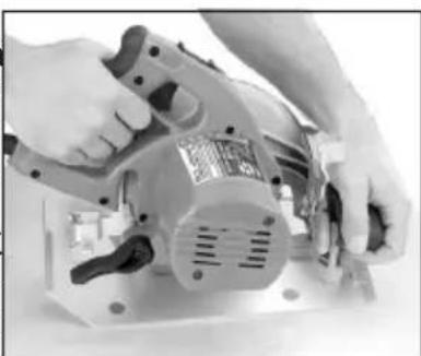
natural_image
Close-up of hands operating a power tool on an electrical machine (no visible text or symbols)natural_image
Close-up of hands operating a mechanical tool with a label (no visible text or symbols on the tool itself)natural_image
Close-up of hands operating a power tool on a cutting board (no visible text or symbols)natural_image
Person operating a power tool on a workbench (no visible text or symbols)natural_image
Person using a power tool on a cutting board (no visible text or symbols)natural_image
Close-up of a mechanical device with visible internal components and a label on the base (no readable text or symbols)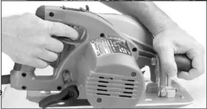
natural_image
Close-up of hands operating a power tool on a flatbed surface (no visible text or symbols)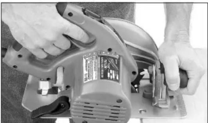
natural_image
Close-up of hands operating a power saw machine with visible brand label (no text or symbols on the device itself)natural_image
Technical line drawing of a mechanical setup with a flatboard and a cutting tool on a base (no text or symbols)Refente du bois
natural_image
Close-up of hands operating a power tool on a workbench (no visible text or symbols)Milwaukee Tool (Canada) Ltd 1.800.268.4015
Monday-Friday, 7:00 AM - 4:30 PM CST
www.milwaukeetool.ca
GARANTIE LIMITÉE- AUX ÉTATS-UNIS ET AU CANADA

natural_image
Close-up of hands using a tool to adjust or install a small mechanical component (no visible text or symbols)natural_image
Close-up of a hand using a power tool on a flat surface, with an arrow pointing to the blade (no visible text or symbols)natural_image
Close-up of a mechanical cutting tool with visible blades and a 6 mm scale indicator (no text or symbols on the tool itself)natural_image
Close-up of hands operating a mechanical device with a black clip, no visible text or symbols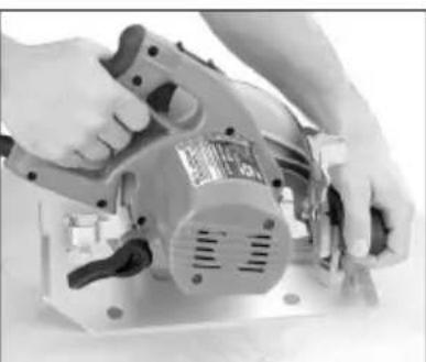
natural_image
Close-up of hands operating a power shaver on an industrial machine (no visible text or symbols)natural_image
Close-up of hands operating a power tool with a label on the blade (no visible text or symbols)natural_image
Close-up of hands operating a power shaver on a metal workbench (no visible text or symbols)natural_image
Person operating a power tool on a workbench (no visible text or symbols)natural_image
Person using a power tool on a workbench, no visible text or symbolsnatural_image
Close-up of mechanical components with visible internal structures and a partially visible card labeled 'HAMD NO.0140V' (no readable text beyond label)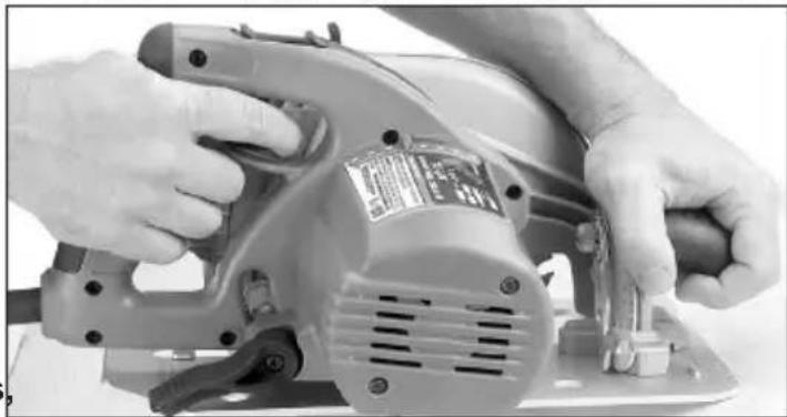
natural_image
Close-up of hands operating a power tool on a flatbed surface (no visible text or symbols)
natural_image
Close-up of hands operating a power tool on a cutting board (no visible text or symbols)Cortando paneles grandes
natural_image
Technical line drawing of a mechanical setup with a tool and base plate (no text or symbols)Cortando a lo largo
natural_image
Close-up of hands operating a power tool on a workbench (no visible text or symbols)Lunes a Viernes (9am a 6pm)
13135 West Lisbon Road
Brookfield, WI 53005 USA
58146391d12 961012830-01(A)
10/18 Printed in China


- ⚠ WARNING Read all safety warnings, instructions, illustrations and specifica-
- WORK AREA SAFETY
- ELECTRICAL SAFETY
- PERSONAL SAFETY
- POWER TOOL USE AND CARE
- SERVICE
- SPECIFIC SAFETY RULES FOR LEFT BLADE CIRCULAR SAWS
- Cutting procedures
- DANGER
- Further safety instructions for all saws Kickback causes and related warnings
- Lower guard function
- SYMBOLOGY
- SPECIFICATIONS
- EXTENSION CORDS
- READ AND SAVE ALL INSTRUCTIONS FOR FUTURE USE.
- GROUNDING
- WARNING
- Grounded Tools (Three-Prong Plugs)
- Double Insulated Tools (Two-Prong Plugs)
- ASSEMBLY
- Selecting Blade
- Rip & Crosscut
- Framing-Rip
- Plywood-Veneer
- Finish & Trim
- Checking the Operation of the Lower Guard
- Installing and Removing Blades
- Adjusting Depth
- Adjusting Tilt-Lok™ Handle Angle
- AWARNING Do not operate saw with handle lever release button pressed in or with handle not locked into position.
- Adjusting the Blade to Shoe
- OPERATION
- AWARNING To reduce the risk of injury, always wear proper eye protection marked to comply with ANSI Z87.1.
- General Operation
- Troubleshooting
- APPLICATIONS
- Selecting Tilt-Lok™ Handle Positions
- Cutting Large Panels
- Ripping Wood
- Cross-Cutting Wood
- ⚠ WARNING To reduce the risk of electric shock, check work area for hidden pipes and wires before making pocket cuts.
- Pocket Cutting
- Cutting Masonry and Metal
- MAINTENANCE
- Maintaining Tools
- Cleaning
- Repairs
- ACCESSORIES
- SERVICE - UNITED STATES
- 1-800-SAWDUST (1.800.729.3878)
- SERVICE - CANADA
- Milwaukee Tool (Canada) Ltd 1.800.268.4015
- LIMITED WARRANTY USA & CANADA
- LIMITED WARRANTY - MEXICO, CENTRAL AMERICA & CARIBBEAN
- Procedure to make this warranty valid
- Exceptions
- Refente du bois
- GARANTIE LIMITÉE- AUX ÉTATS-UNIS ET AU CANADA
- Cortando paneles grandes
- Cortando a lo largo
Brand : MILWAUKEE
Model : 639121
Category : Electric saw