FBCD 762 TNF EDBL - Fridge Fulgor Milano - Free user manual and instructions
Find the device manual for free FBCD 762 TNF EDBL Fulgor Milano in PDF.

User questions about FBCD 762 TNF EDBL Fulgor Milano
0 question about this device. Answer the ones you know or ask your own.
Ask a new question about this device
Download the instructions for your Fridge in PDF format for free! Find your manual FBCD 762 TNF EDBL - Fulgor Milano and take your electronic device back in hand. On this page are published all the documents necessary for the use of your device. FBCD 762 TNF EDBL by Fulgor Milano.
USER MANUAL FBCD 762 TNF EDBL Fulgor Milano
natural_image
Simple geometric diagram with two vertical lines inside a larger rectangle (no text or symbols)FBCD 761 TNF EDBL
FBCD 762 TNF EDBL
FRIGORIFERO
FRIDGE
RÉFRIGÉRATEUR
KÜHLSCHRANK
REFRIGERADOR
FRIGORÍFICO
∅8,0 Punta per trapano
Taglierino

Guanti protettivi

Metro a nastro

Punta a stella
Chiava a bussola da 7 mm (1/4")

Livella a bolla
Carrello

Nastro


AVVERTENZA
natural_image
3D line drawing of a two-door cabinet with door labels and internal compartments (no text or symbols)natural_image
Technical line drawing of an open refrigerator with labeled door and side panel (no text or symbols)FBCD 761 TNF EDBL FBCD 762 TNF EDBL
A 824mm (32 7/16")
B 756mm (29 3/4")
C 1398mm (55 1/32")
FBCD 761 TNF EDBL FBCD 762 TNF EDBL
A 1127mm (443/8")
B 756mm (29 3/4")
C 371mm (14 5/8")
D 1338mm (52 11/16")
FBCD 761 TNF EDBL
FBCD 762 TNF EDBL
natural_image
Three icons: a manual push cart, two hard hats with overalls, and one person in a hard hat (no text or symbols)natural_image
3D line drawing of a rectangular cabinet or enclosure with three vertical panels stacked vertically (no text or symbols)natural_image
Exploded view diagram of a server rack unit with internal components and mounting brackets (no text or labels)
ATTENZIONE
natural_image
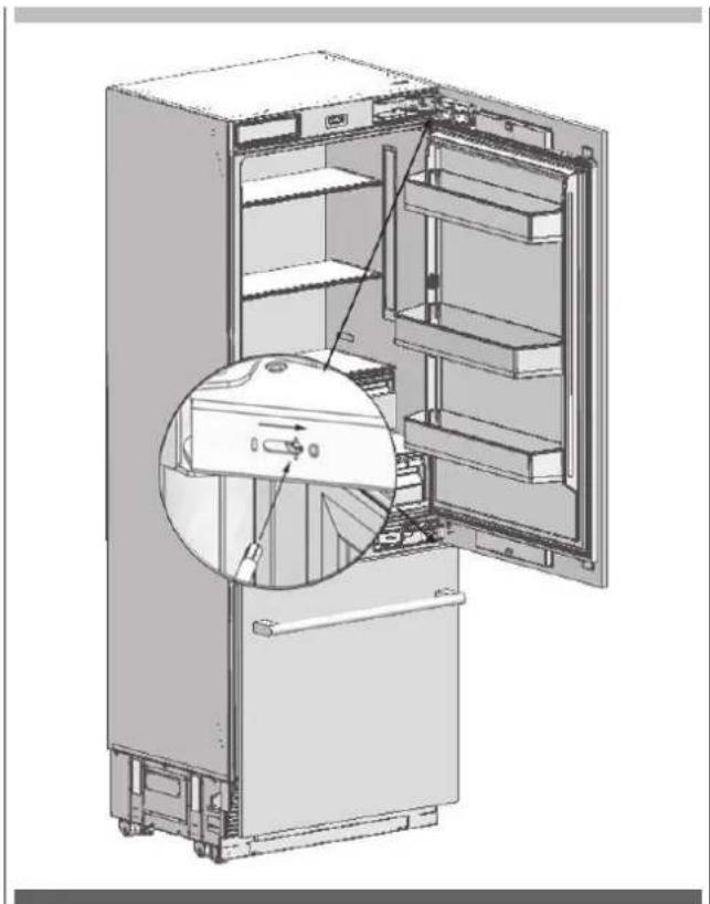
Technical illustration of an internal storage or rack system with a magnified inset showing a component detail (no text or symbols present)natural_image
3D technical illustration of a mechanical device with internal components and mounting base (no visible text or symbols)natural_image
Technical illustration of a mechanical assembly with an inset close-up showing a component detail (no text or symbols present)natural_image
Diagram of a refrigerator interior showing door, drawer, and shelf with an inset close-up of the tray (no text or symbols)natural_image
Technical line drawing of a mechanical assembly with mounting base and internal components (no text or symbols)natural_image
Technical line drawing of a mechanical assembly with mounting base and structural components (no text or symbols)
AVVERTENZA
natural_image
Technical illustration of a mechanical assembly with a circular component and mounting base (no text or symbols)natural_image
Technical illustration of a mechanical device with a handrail and a vertical panel, showing a directional arrow (no text or symbols present)
ATTENZIONE
natural_image
Technical illustration of a server rack with cable routing and a close-up inset showing internal components (no text or symbols)
natural_image
Two black-and-white icons: a stylized tool and a screwdriver, both without any text or symbols.
AVVERTENZA
natural_image
Technical line drawing of an industrial machine interior with no visible text or symbolsnatural_image
Technical line drawing of a cabinet with an inset showing a cross-section detail (no text or symbols)natural_image
Technical illustration of an open refrigerator with internal compartments and a close-up inset showing the front panel (no text or symbols present)
natural_image
Interior view of a refrigerator showing open doors, shelves, and internal compartments with arrows indicating flow direction (no text or symbols)natural_image
Line drawing of a refrigerator interior showing front and rear compartments with no text or symbolsIT INSTALLAZIONE PARTE INFERIORE CABINET FRIGORIFERO
Collegamento idrico
natural_image
Technical illustration of an industrial machine with two wrench icons and a close-up view of internal components (no text or symbols)natural_image
Technical line drawing of a mechanical assembly with no visible text or symbolsnatural_image
Technical illustration of a server rack unit with ventilation grilles and a tool icon (no text or symbols)
natural_image
Technical line drawing of a refrigerator interior showing front and side views (no text or symbols)natural_image
Line drawing of a front view of a computer oven with ventilation slots and a door (no text or symbols)
AVVERTENZA
natural_image
Technical diagram showing a bracket assembly with mounting holes and a tool icon (no text or symbols)natural_image
Technical illustration of an open refrigerator with internal compartments and mounting hardware (no text or symbols)natural_image
Technical illustration of a mechanical assembly with cutouts and mounting brackets (no text or symbols)IT
natural_image
Pure technical diagram of a mechanical assembly with no text, numbers, or symbols
AVVERTENZA
natural_image
Diagram showing a mechanical assembly with a bracket and force arrows, no text or symbols presentnatural_image
Simple 3D diagram of a rectangular block with three small protrusions and an upward arrow, no text or symbols present.natural_image
Pure technical diagram of a mechanical assembly with no text, numbers, or symbolsnatural_image
Diagram of a mechanical lever system with motion arrows indicating rotational motion (no text or symbols)
natural_image
Technical diagram of a mechanical assembly with two vertical supports and directional arrows indicating movement (no text or symbols present)natural_image
Simple line drawing of a triangular structure with an arrow indicating rotation, no text or symbols present.natural_image
Technical line drawing of a multi-level rack cabinet with mounting feet and top panel (no text or symbols)IT
natural_image
Technical diagram of an electrical enclosure with internal components and a magnified inset showing a component detail (no text or symbols present)natural_image
Technical line drawing of a refrigerator with an inset close-up showing internal components (no text or symbols)
natural_image
Technical diagram of a mechanical assembly with a magnified inset showing internal components (no text or symbols)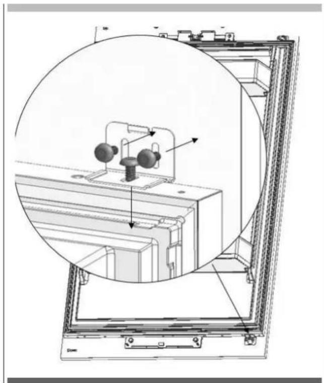
natural_image
Technical diagram of an electrical enclosure with internal components and a circular inset view (no text or symbols)natural_image
Interior view of a refrigerator showing open doors and internal compartments, with an inset close-up highlighting the exterior panel (no text or symbols visible)natural_image
Interior view of a refrigerator showing open doors, shelves, and storage compartments (no text or labels)
AVVERTENZA
natural_image
Diagram showing a mechanical assembly inside a room with an inset close-up of a tool interacting with a component (no text or symbols visible)natural_image
Technical line drawing of a mechanical assembly with no visible text or symbolsnatural_image
3D technical illustration of an open refrigerator with internal compartments and mounting hardware (no text or symbols)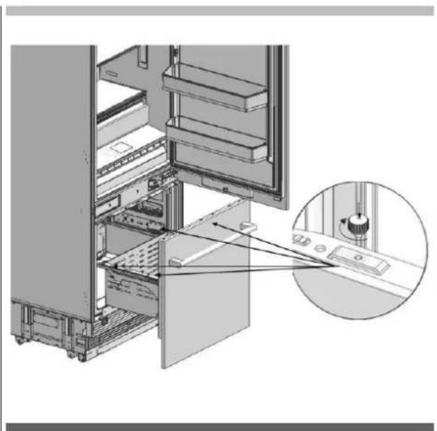
natural_image
Technical diagram of an internal server rack with a close-up inset showing the component (no text or symbols present)natural_image
Technical line drawing of a door frame with horizontal bars and arrows indicating assembly or measurement (no text or symbols)natural_image
Technical line drawing of a refrigerator panel with door, vent, and side panels (no text or symbols)IT REGOLAZIONE DELLE CERNIERE
natural_image
Interior view of a refrigerator showing open doors and internal shelves, with a magnified inset highlighting the interior portion (no text or symbols visible)
AVVERTENZA
natural_image
Diagram of an open refrigerator showing internal shelves and door, with a magnified inset highlighting the interior structure (no text or symbols present)
ATTENZIONE
natural_image
Technical line drawing of a door frame with three horizontal bars and vertical supports (no text or symbols)natural_image
Technical diagram of a door frame assembly with mounting bracket and control panel (no text or symbols)natural_image
Technical diagram showing a device mounted on a bracket with arrows indicating assembly or adjustment (no text or symbols present)natural_image
Diagram showing a server rack with two car doors and a close-up of the door, no text or symbols present.natural_image
Technical illustration of an open refrigerator with a magnified inset showing internal components (no text or symbols)natural_image
Technical line drawing of an open refrigerator with visible door, shelves, and internal components (no text or symbols)
natural_image
Technical illustration of an open refrigerator with a close-up inset showing internal components (no text or symbols)natural_image
Technical line drawing of a structural frame with internal components and directional arrows (no text or symbols)TABLE OF CONTENTS PAGE
Symbols and Their Meanings 2
Installation Place 3
Tool list 5
ALTERNATIVES FOR INSTALLATION 6
PREPARATION FOR INSTALLATION 7
Cabin Dimensions 7
Location of the Electrical Wiring 7
Location of the Water System 8
Product Dimension 9
Unpacking 12
Removing connectors on the rear wall 13
Removing mounting Parts in the Freezer Compartment 14
Removing the FRZ Crisper 15
Removing the FRZ Door 15
Removing the Lower Vent Hole Assembly 16
Removing the Upper Vent Hole Part 16
PRE-INSTALLATION 17
Mounting the Anti-Tip Brackets 17
Alternative anti-tip method 18
Preparing the Water Hose and the Power Plug 18
INSTALLATION TO THE CABIN 19
Taking the Refrigerator from the Wooden Pallet 19
Placing the refrigerator into the cabin 19
Adjusting the height of the refrigerator in the cabin 21
Adjusting the refrigerator according to the cabin flange 21
Screwing the side brackets 22
Screwing the upper bracket 23
TABLE OF CONTENTS PAGE
INSTALLING THE CABIN BOTTOM 24
Water connection 24
Attaching the upper vent hole part 24
Attaching the lower vent hole assembly 25
Attaching the decorative parts 25
FURNITURE DOOR PREPARATION 26
Choosing the Door Thickness 26
Removing the Mechanism Covers 28
Removing the Panel-Adjustment Mechanisms on the Refrigerator 28
Preparing Furniture Door 29
Preparing the Fridge Furniture Door 29
Preparing the Freezer Furniture Door 30
Installing the Fridge Furniture Door 31
Installing the Freezer Furniture Door 33
HINGE ADJUSTMENT 36
Adjusting the hardness of the hinges 36
CHANGING THE DIRECTION OF THE FF DOOR 37
Removing the FF clad door 37
Removing and preparing the Fridge Inner Door 39
Replacing the hinges 40
Installing the FF PU Door 42
Symbols and Their Meanings
Symbols used in the installation manual are as follows.
 | Important information or useful usage tips |
 | WARNING: Conditions that may damage the product or its operating functions |
 | ATTENTION: Conditions containing serious injury risk |
 | Conditions containing electric shock risk |
 | Packaging materials of the product have been manufactured from recyclable materials in accordance with our National Environment Regulations. |
Disposing the packaging materials
The package has been designed to protect the product during transport.
The packaging materials used for the product do not harm the nature during disposal and they need to be recycled.
All plastic packaging materials, bags etc. must be disposed safely and kept out of the reach of children.
Please return the packaging to your dealer.

WARNING
This installation manual has been prepared to help installation teams. The User Manual provided with the product must also be taken into consideration.
You may get seriously injured and your product may get damaged if you ignore the warnings given in this manual. Please read the following carefully.

WARNING
R600a Refrigerant
This product contains R600a isobutane refrigerant, which is a very eco-friendly natural gas. However, it is also flammable. Please follow the warnings given below:
- If the product has been transported horizontally, you must wait for 4 hours minimum before plugging it in.
- The following instructions must be followed during installation:
- Dimensions of the installation area must be suitable.
- Dimensions, features and position of the object used to support and fix the product to this area must be suitable.
- Minimum clearances between product parts and surrounding structures must be suitable.
- Minimum dimensions and proper organisation of ventilation holes must be observed.
- The product must be connected to the mains power, and corresponding connections of other components must be suitable.
- The product must be disconnectable from the power supply after installation.
- The socket or fuse must be accessible to de-energise the product.
- Extension cables or ungrounded (two-terminal) adapters must not be used.

ATTENTION
You must wear gloves and eye protectors when installing the product.
You must also take measures against high noise levels when drilling the floor or using a drill.
Make sure that your product is suitable for your local mains.
The product must be installed by a qualified technician according to the installation instructions.

WARNING
The product may tip over since it is quite heavy. For this reason, precautions must be taken against tipping over.
The doors of the product must be kept closed until it reaches the destination and it must be transported in accordance with the installation instructions.
Climate class
| Climate range | Ambient temperature of the room | |
| SN | Between +10°C (50°F) and +32°C (90°F) | This appliance has been designed to be used in certain climate ranges (ambient temperatures). It must not be used out of this range. |
| N | Between +16°C (60°F) and +32°C (90°F) | |
| ST | Between +16°C (60°F) and +38°C (110°F) | |
| T | Between +16°C (60°F) and +43°C (120°F) | |
Product weight:
FBCD 761 TNF EDBL
FBCD 762 TNF EDBL
Product weight 164kg (361lbs)
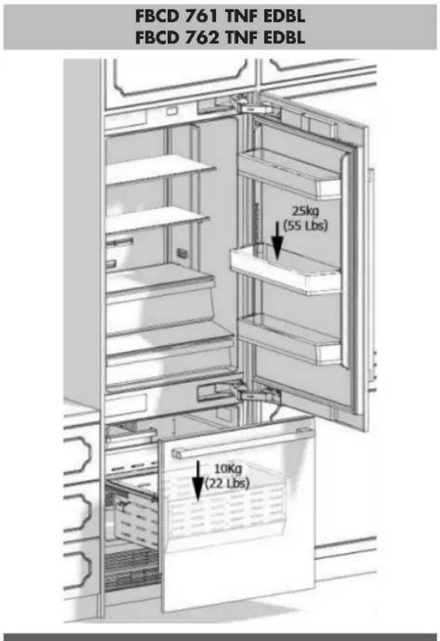
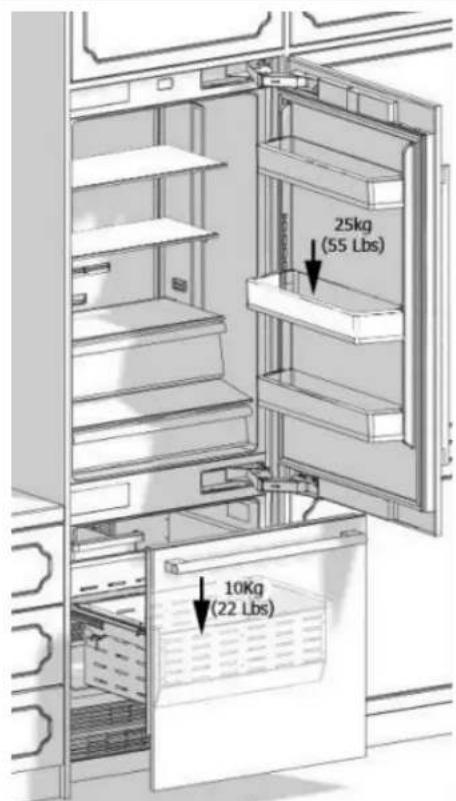
Load bearing capacity of the doors
| Max load | FBCD 761 TNF EDBL |
| FBCD 762 TNF EDBL | |
| Fridge door 25kg (55lbs) | |
| Freezer door 10kg (22lbs) | |
Installation Place
You must follow the instructions below:
- The floor on which the product will be installed must be capable of bearing 544 kg (1,200 pounds) minimum.
- Kitchen floor and the bottom of the product must be at the same level. Otherwise, problems may occur with the air suction of the product.
- There must be no objects preventing the installation of the product at the back and on the side walls of the product's installation place.
• The power socket must be at the correct place. - Dimensions of the furniture where the product will be installed must be in strict conformity with the dimensions given in the manual.
- Do not install the product with the fridge and the freezer are adherent next to each other. Otherwise, condensation and damage may occur in the product. (Please see "Dual Cabin Installation" for detailed information)
- Flatness of the floor where the product will be installed must be checked with a Bubble Level Tool.
• Installation area must not be subjected to direct sunlight and it must be away from heat sources, ovens, radiators etc. - The ambient temperature must be between 13°C (55°F) and 43°C (110°F). Otherwise,
• function errors may arise when the product is running. - If it is not possible to avoid installing the product near a heat source, the minimum clearances given below must be maintained between the product and the said source:
• 3 cm (1 1/4") from electric hobs or ovens.
• 30 cm (12") from gas or fuel operated hobs or ovens.
Please observe the following rules:
- The power socket or fuse must be easily accessible in case of an emergency; it must not be hidden behind the product.
- Plug or cable must not touch the back surface of the product. Otherwise, it may get damaged due to the vibration of the product.
- Do not connect the plugs of other appliances behind this product. If the humidity level is high where the product is used, corrosion may be seen on the outer surface of the product. Keep the installation room dry and well-cleaned to avoid corrosion.
To avoid the risk of electric shock: - Connect the plug to a grounded 3-pin socket.
- Do not remove the ground terminal of the plug.
- Do not use adapters.
• Do not use extension cables.

ATTENTION
Failure to follow these instructions may result in death, fire or electric shock. Connecting the grounding conductor of the equipment to an improper place may lead to electric shock. Please have the grounding checked by a qualified electrician or service technician if you have any doubt about the proper grounding of the product.
Installation, repair and other procedures performed by unqualified persons may cause danger. Before installing the appliance, make sure that the voltage, load and circuit current parameters on the data plate are in compliance with the power mains in your house.
The appliance is provided with a plug and power cable which is ready to be connected to a 220-240V 50/60HZ power supply. The appliance must be connected to a 3-pin socket. The plug must be installed only by a licensed electrician.
If the electrical wiring or the electric power supply of the house needs alteration, the necessary procedures must be performed by a qualified electrician.

ATTENTION
Do not install your refrigerator:
- In open areas
• In environments where water is dripping - In environments where temperature is lower than (55°F)
Furniture:
Make sure that the furniture where you will install the appliance has been safely mounted in your kitchen.
Your furniture must be connected to the floor and the wall properly and with suitable connections.
For the best installation, clearances between the furniture and the product must be in compliance with the values specified in the installation instructions.
Side walls must be free of clearances and their surfaces must be flat.
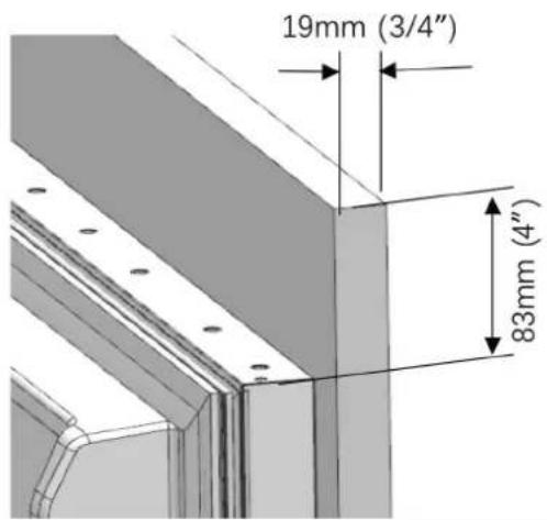
Minimum thickness of the side walls must be 16 mm (5/8"). Minimum thickness of the doors to be attached to the product must be 19 mm (3/4").

ATTENTION
It is possible to purchase a stainless steel door panel kit.
Ventilation:
Vent holes where the air enters and exits the unit must not be blocked or obstructed. In addition, you must periodically clean the dust and dirt that accumulate on these holes in time.
Electrical Connection:
- Never use an extension cable.
- The power socket must definitely be grounded and checked by an authorised person.
- Location of the electrical wiring must comply with the dimensions specified in the manual.

ATTENTION
RISK OF ELECTRIC SHOCK
Electrical grounding is necessary. This appliance is equipped with a three-pin plug to protect you against possible electric shocks.
- Do not remove the round grounding terminal from the plug.
- Do not use two-pin grounding adapters.
- Do not use extension cables to energise the product.

ATTENTION
Do not connect the grounding cable to the gas pipe. Please have the grounding checked by a qualified electrician if you are not sure about the grounding of the product. Do not install a fuse on the neutral line or grounding circuit.
0°C

WARNING
Please wait for 3-6 hour before energising the product to protect it against possible damages. This way, the refrigerant and the lubricants in the system get balanced.
Water Connection
- Pressure of the mains water must be in compliance with the values specified in the manual.
- Location of the water system must comply with the dimensions specified in the manual.

IMPORTANT INFORMATION
Bypass is recommended for the water filtering system if a reverse osmosis system is used.
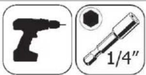
Tool list
Tools to be used when installing the product are as follows:
Cordless Drill
Safety Goggles
1/2" Wrench

Hammer
Ladder
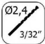
∅2.4 Drill bit

∅8.0 Drill bit
Box Cutter

Safety Gloves

Tape measure
Star bit
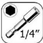
1/4" Wrench Flat
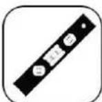
Bubble Level Tool

Wheelbarrow

Tape
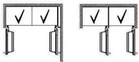
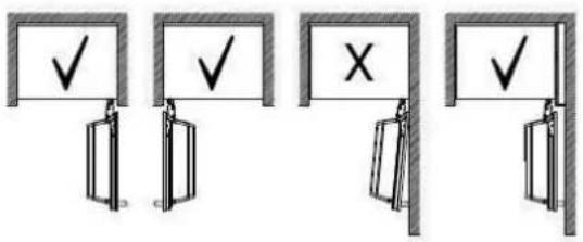
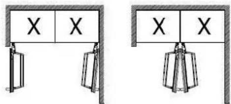
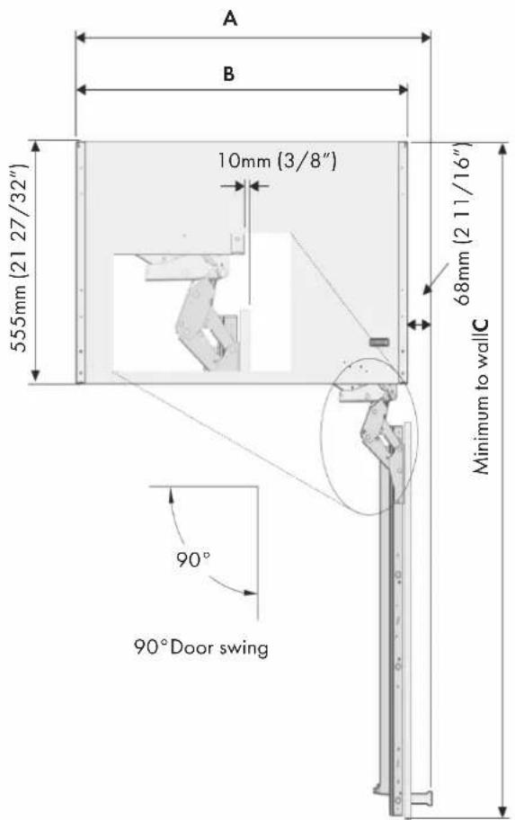
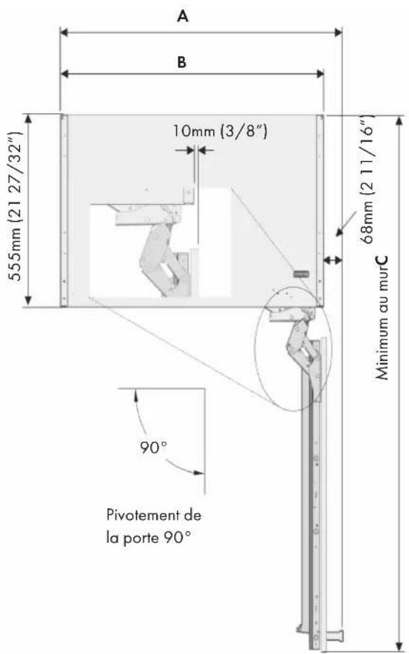
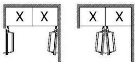
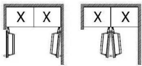
The product can be placed in various ways based on the kitchen design. It must be installed at a place where it is ensured that the door can be opened and closed properly. If the doors cannot be opened 90 degrees at least, you cannot completely open the drawers inside the product.
Single cabin placement methods
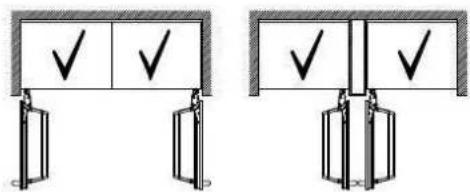
Dual cabin placement methods
The instructions below have been prepared according to Built-in type.
Built-in: The Appliance and Panels fully seat into the gap, and a material that can be their own box is jammed between the two kitchen cabinets or decorative columns.
This is the most common installation scenario.
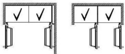
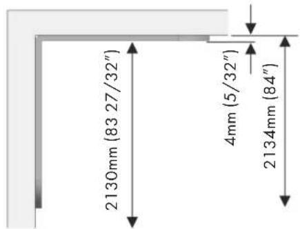
Cabin Dimensions
- Cabin dimensions below must be checked before starting the installation.
FBCD 761 TNF EDBL FBCD 762 TNF EDBL
| A width 762mm (30") |
| B depth 635mm (25") |
| C height 2134mm (84") |
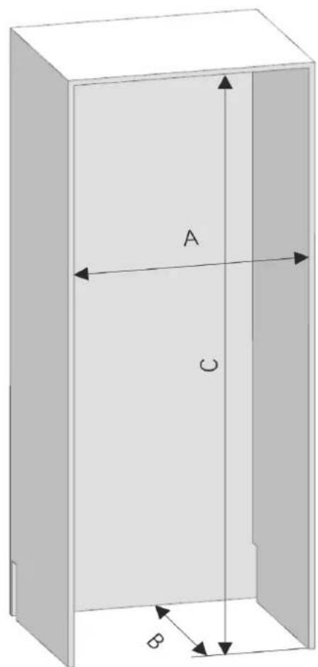
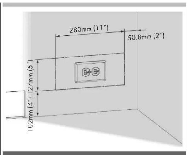
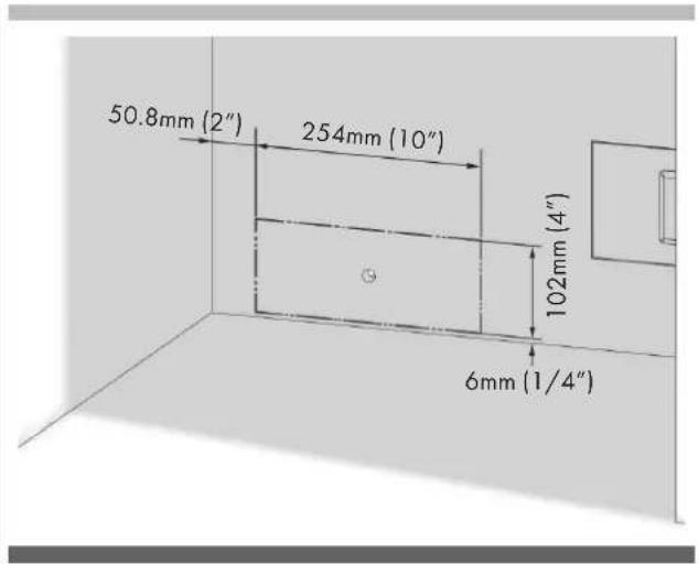
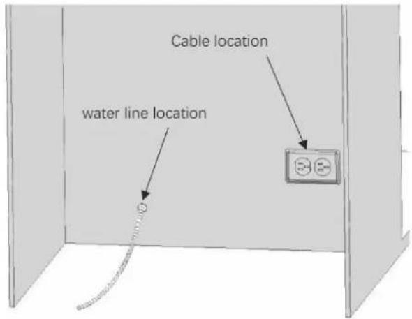
Location of the Electrical Wiring
Location of the electrical wiring must be within the range given below.

ATTENTION
Do not use extension cables or two-pin adaptors and do not remove the ground terminal of the grounding cable.

ATTENTION
A qualified electrician must ensure that the poles of the socket are connected correctly. Verify that the grounding of the socket is correct.
Location of the Water System (only for model FBCD 762 TNF EDBL)
The water connected to the water mains must be potable.
Location of the water system must be within the range given below.
Water system of the refrigerator must be connected to the water mains system in the house.
The user must be able to switch it on/off with the valve when necessary.
Objects that might pierce the water hoses or cause them to twist must not be present where the water line is installed.
Pressure of the water system must be between 25-80 psi (1.7-5.5 Bar).
If the water pressure exceeds 80 psi, install a pressure limiting device or water impact protector to the inlet valve.
Never install the product or operate the appliance if it is possible for the water pressure to exceed 120 psi.

WARNING
Make sure that there is no water leakage when making the water connections. Otherwise,
there will be water on the floor and the furniture will get damaged.
You will need a hose with a minimum length of 1.5 meters (60") and a diameter of 1/4" for water connections of the product during installation.
A connector that has a thread with an external diameter of must be used to connect the hose end to the product.
Before completing the installation, make sure that water flows and there is no water leakage.

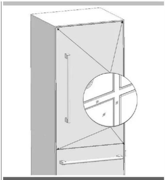
WARNING
- Flatness of the floor where the product will be installed must be checked with a Bubble Level Tool.
- Uprightness of the furniture flanges must be checked with a Bubble Level Tool.
- If the flatness and uprightness of the product is not proper, problems may arise with the installation.
natural_image
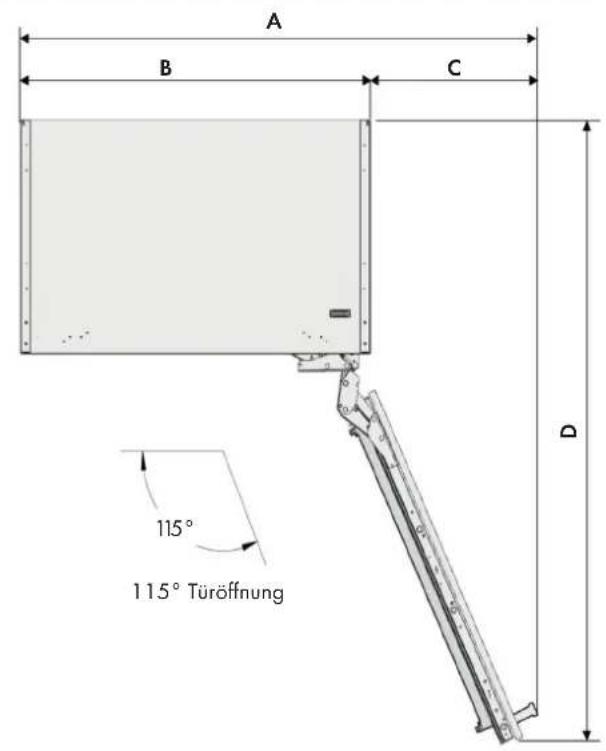
3D line drawing of a two-door cabinet with doors open and one door closed, showing internal structure (no text or symbols)Product Dimension
FBCD 761 TNF EDBL FBCD 762 TNF EDBL
A 756mm (29 3/4")
without panel: 592mm (23 5/16")
with panel 19 mm (3/4"):616mm (24 1/4)
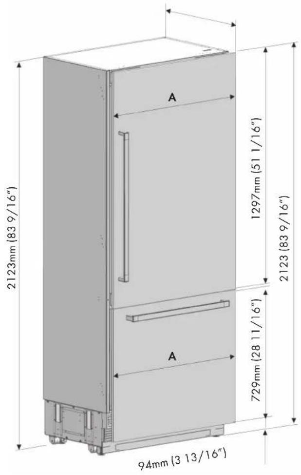
FBCD 761 TNF EDBL FBCD 762 TNF EDBL
A 388mm (15 9/32")

natural_image
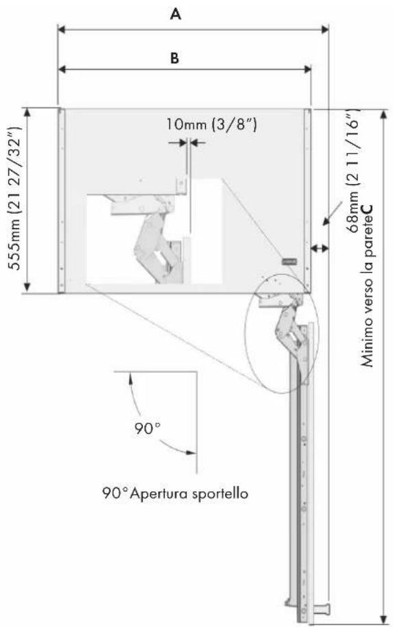
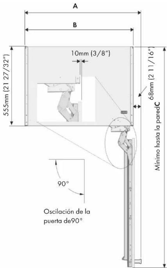
Technical line drawing of an open refrigerator with labeled door and side panel (no text or symbols)FBCD 761 TNF EDBL FBCD 762 TNF EDBL
A 824mm (32 7/16")
B 756mm (29 3/4")
C 1398mm (55 1/32")
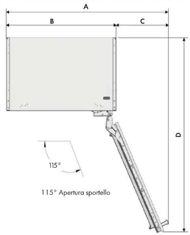
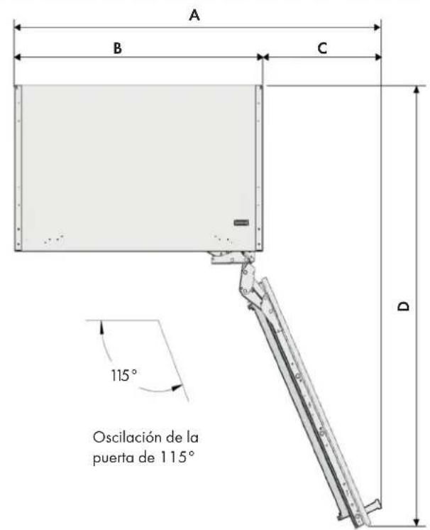
FBCD 761 TNF EDBL FBCD 762 TNF EDBL
A 1127mm (443/8")
B 756mm (29 3/4")
C 371mm (14 5/8")
D 1338mm (52 11/16")

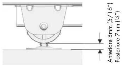
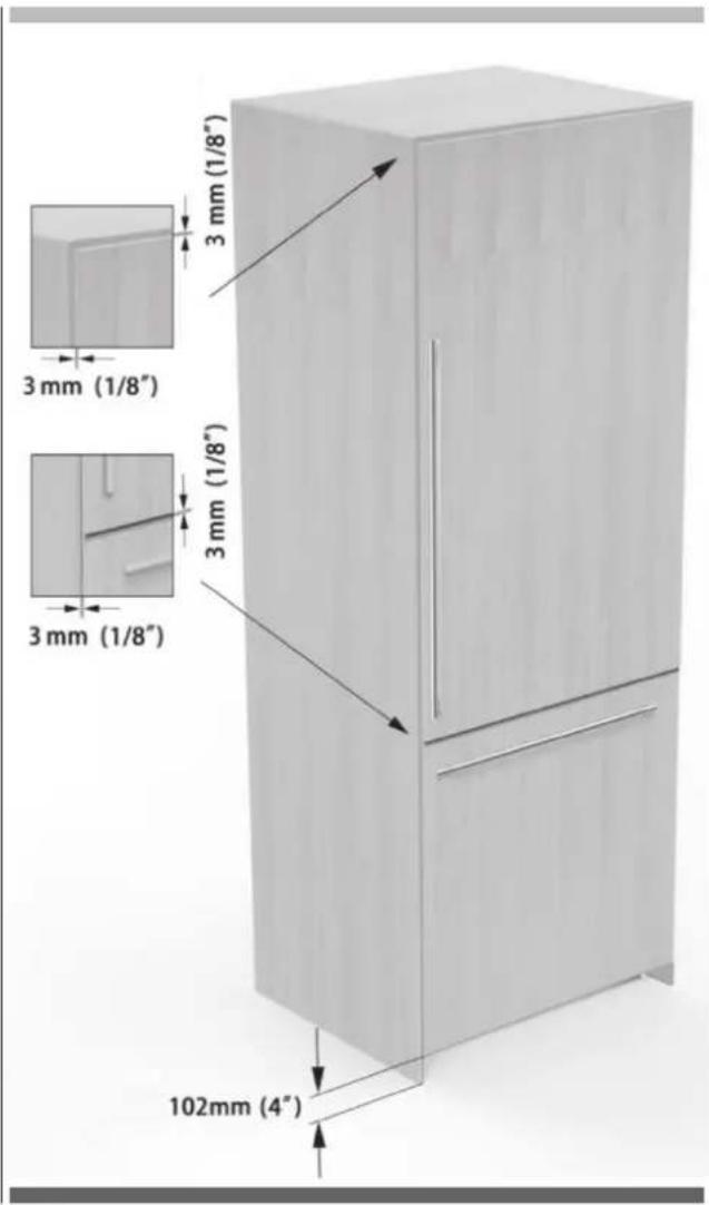
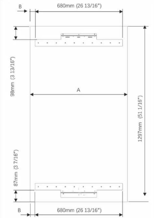
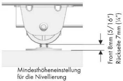
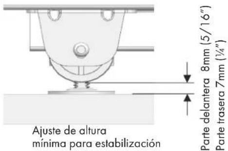
Anti tip bracket location

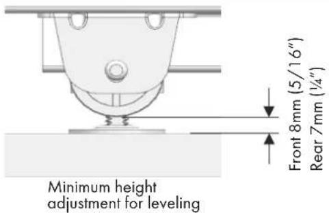
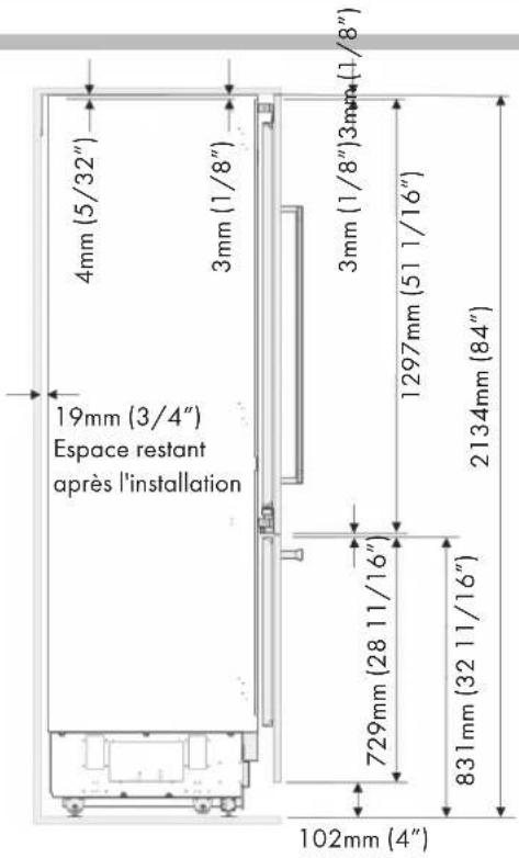
Minimum height adjustment for leveling
FBCD 761 TNF EDBL
FBCD 762 TNF EDBL
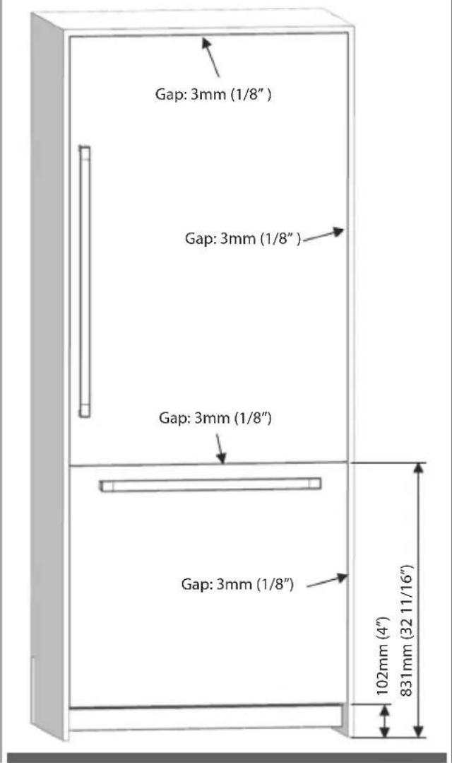
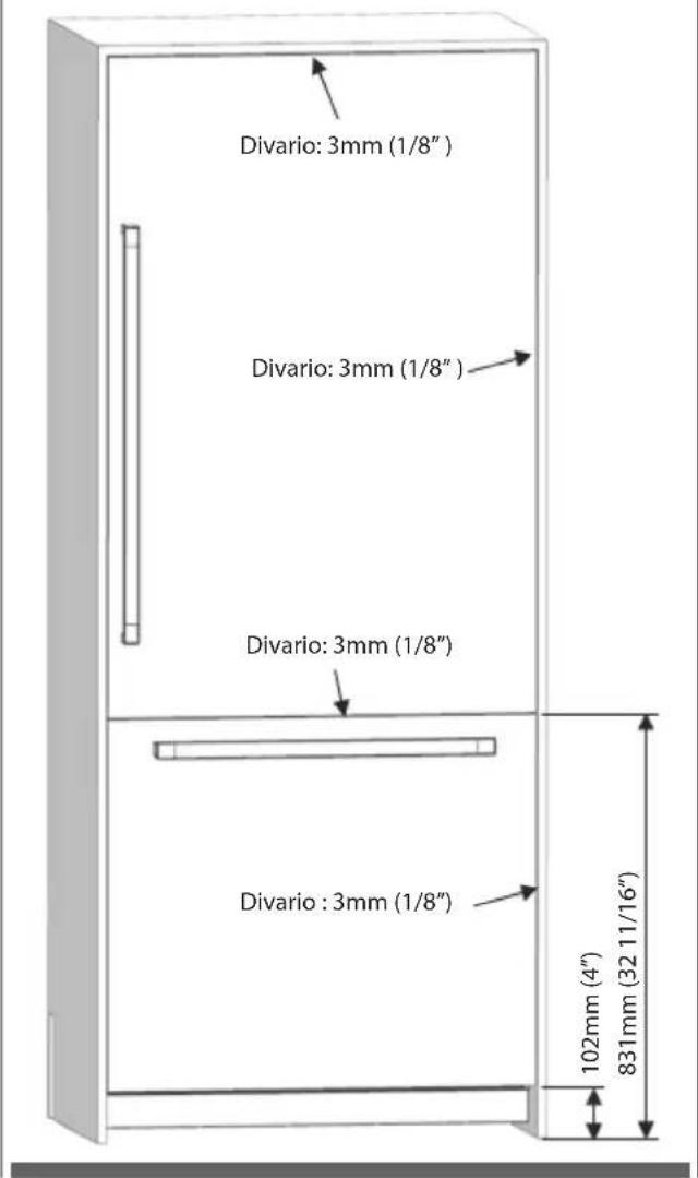
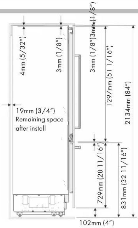
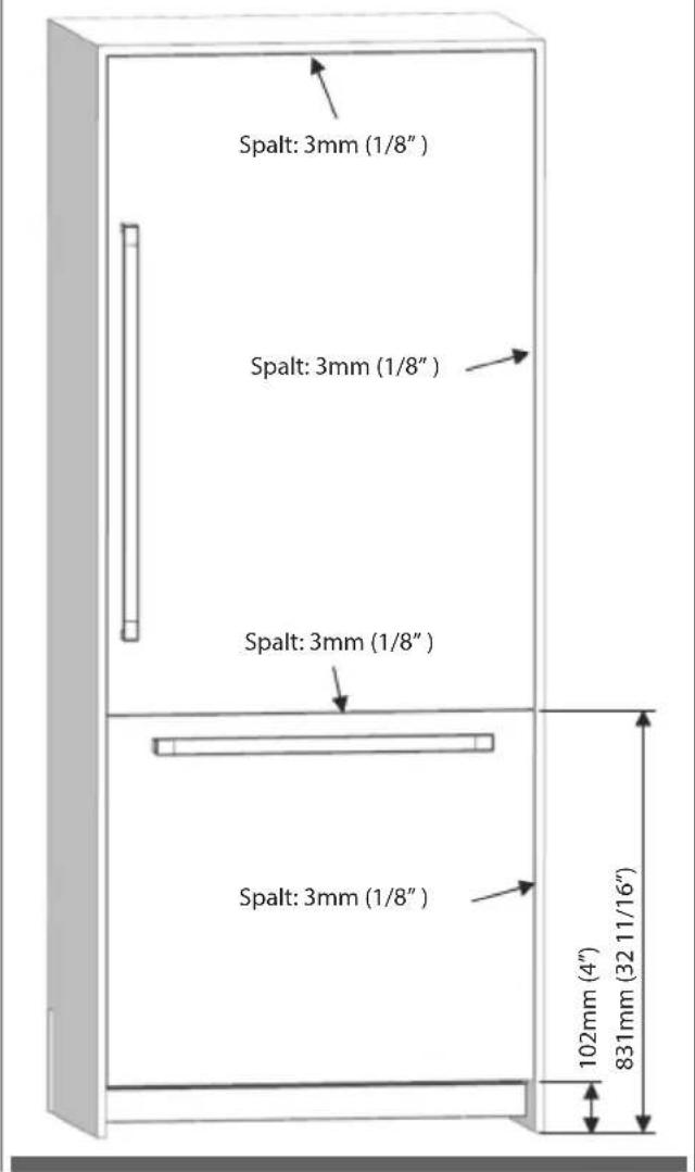
Height of the kitchen countertop based on the min/max. height of the cabin;
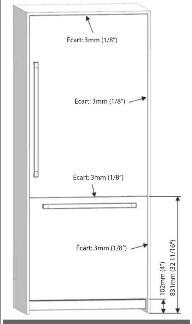
| A B C | |||
| standard | 102mm(4") | 831mm(32 11/16") | 2134mm(84") |
| minimum | 97 mm(3 13/16") | 826mm(32 1/2") | 2129mm(83 13/16") |
| maximum | 137 mm(5 3/8") | 866mm(34 1/8") | 2169mm(85 3/8") |
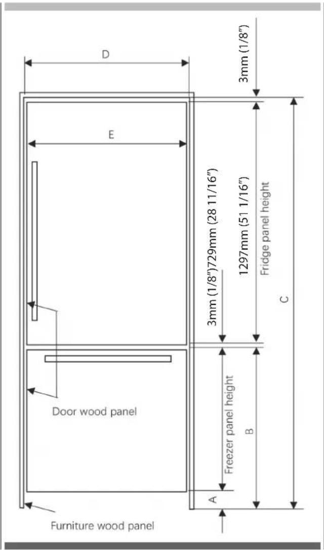
| FBCD 761 TNF EDBL |
| FBCD 762 TNF EDBL |
| D 762mm (30") |
| E 756mm (29 3/4") |
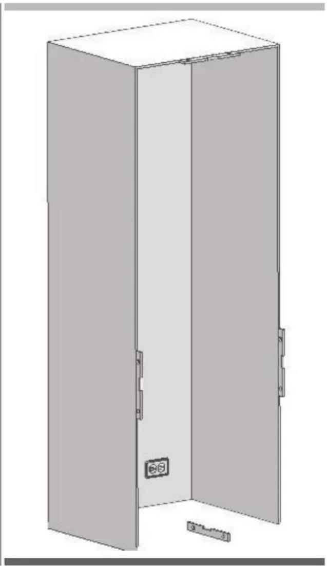
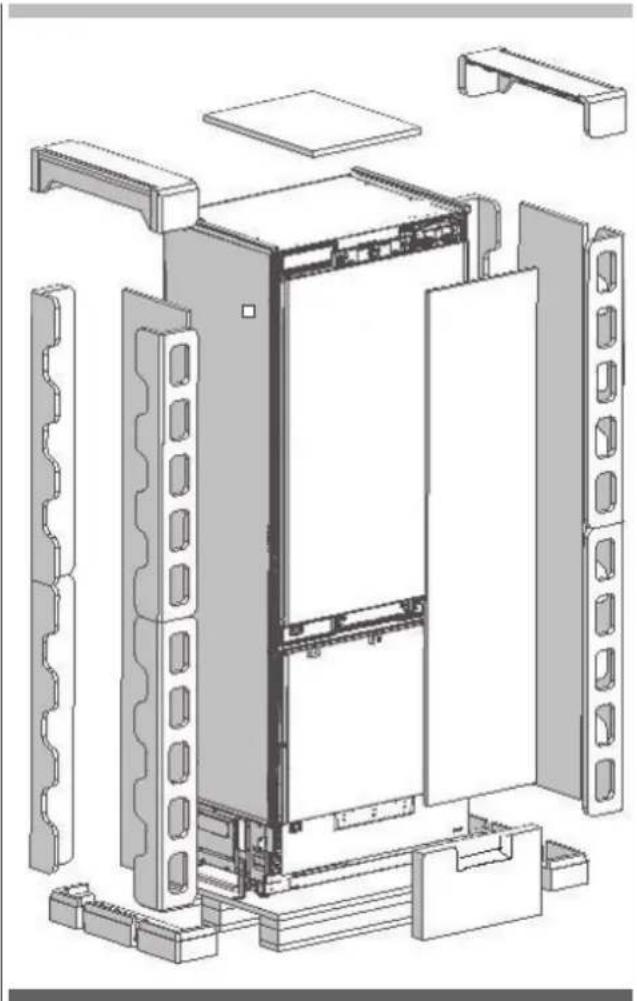
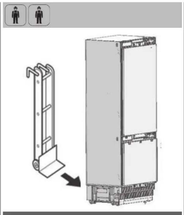
Unpacking

WARNING
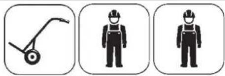
At least two persons must carry the refrigerator.
natural_image
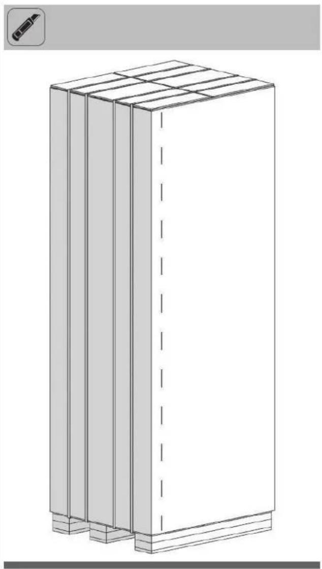
Three icons: a manual push cart, two hard hats with overalls, and one person in a hard hat (no text or symbols)• Use a box cutter to remove the tapes.
- Cut the Packaging Board with a Box Cutter through the section illustrated in dotted lines and remove it.
natural_image
3D line drawing of a rectangular cabinet or enclosure with three vertical panels and a horizontal base, no text or symbols present.- Remove the Packaging Polystyrene material
natural_image
Exploded view diagram of a server rack unit with internal components and mounting brackets (no text or labels)
WARNING
Do not remove the tape of the upper door on the product until the refrigerator is placed into the cabin. Risk of tipping over.
Removing connectors on the rear wall
flowchart
graph TD
    A["Step 1"] --> B["Step 2"]
    B --> C["Step 3"]
    C --> D["Step 4"]
    D --> E["Step 5"]
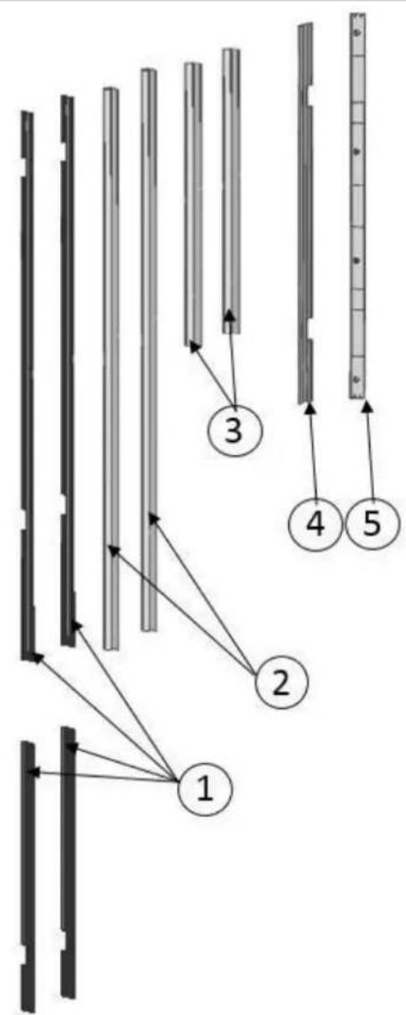
| No Part name spec 76 91 92 | |||||
| 1 Trim fridge furniture side | PVC extrusion L=617mm (24 1/4"),L=1259 mm (49 5/8") | 4 4 4 | |||
| 2 | Trim fridge door side | PVC extrusion L=1136mm (44 3/4") | 2 | 2 | 4 |
| 3 | Trim freezer door side | PVC extrusion L=556 mm (21 7/8") | 2 | 2 | 2 |
| 4 Trim fridge furniture top | PVC extrusion L=762 mm (30"),L=914 mm (36") | 1 1 1 | |||
| 5 | Cover freezer door top | abs | 1 | 1 | 1 |
Removing mounting Parts in the Freezer Compartment
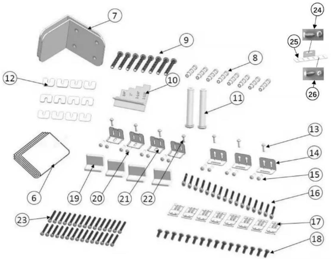
| No Part name spec 76 91 92 | |||||
| 6 Template Furniture door paper 1 1 1 | |||||
| 7 Anti tip bracket T4.0, Zn-coating 2 2 2 | |||||
| 8 Dowel - 8 8 8 | |||||
| 9 | Screw anti tip bracket screws | M8*60 | 8 | 8 | 8 |
| 10 | Position adjustment jig | ps | 1 | 1 | 1 |
| 11 | 90° limiting pins | sus | 2 | 2 | - |
| 12 | Spacer freezer furniture door | abs | 9 | 9 | 9 |
| 13 | Screw freezer furniture door top | ST M4.8x16 | 3 | - | - |
| 14 | Bracket freezer furniture door top | T1.0, sus | 3 | - | - |
| 15 | Screw freezer furniture door top | M4*12 | 6 | - | - |
| 16 | Screw furniture bracket | M4*12 | 16 | 16 | 16 |
| 17 | Bracket furniture | T1.0, Zn-coating | 8 | 8 | 8 |
| 18 | Screw furniture bracket | ST M4x14 | 16 | 16 | 16 |
| 19 | Cover furniture door bracket | abs | 4 | 4 | 2 |
| 20 | Screw furniture door bracket | M4*12 | 8 | 8 | 4 |
| 21 | Bracket furniture door | T1.0, sus | 4 | 4 | 2 |
| 22 | Screw furniture door bracket | ST M4x14 | 8 | 8 | 4 |
| 23 | Screw furniture door hanger bracket | ST M4x14 | 30 | 30 | 34 |
| 24 | Screw freezer furniture door top | ST M4.8x16 | - | 3 | 3 |
| 25 | Bracket freezer furniture door top | T1.0, sus | - | 3 | 3 |
| 26 | Screw freezer furniture door top | M4*12 | - | 18 | 18 |
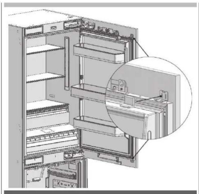
Removing the FRZ Crisper
- Remove it manually with 4 knurled screws
natural_image
Technical illustration of a server rack with an open door and internal compartments, showing a close-up inset (no text or symbols)- Remove the Lower Crisper.

natural_image
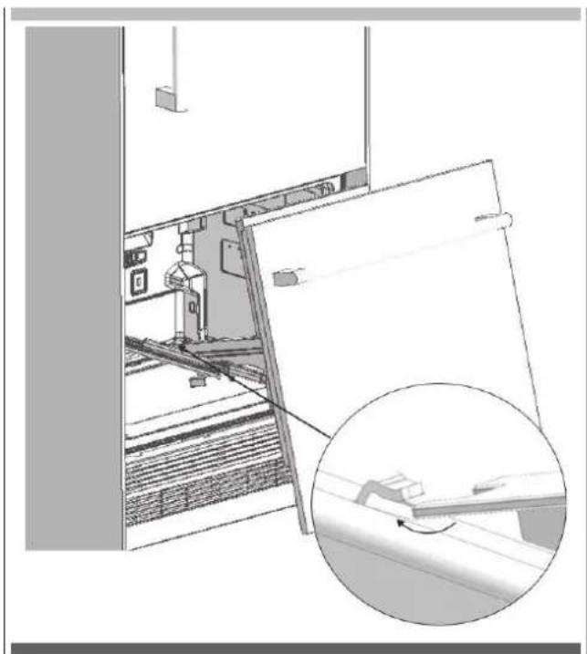
3D technical illustration of a mechanical device with internal components and mounting base (no visible text or symbols)Removing the FRZ Door
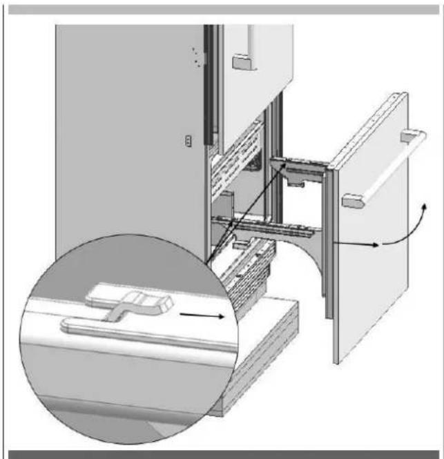
- Remove 2 screws which are near the front section and connect the FRZ Door and the rail.
natural_image
Technical illustration of a mechanical assembly with an inset close-up showing a component detail (no text or symbols present)- Pull the door frontward to free it from the tabs at the back and remove it
natural_image
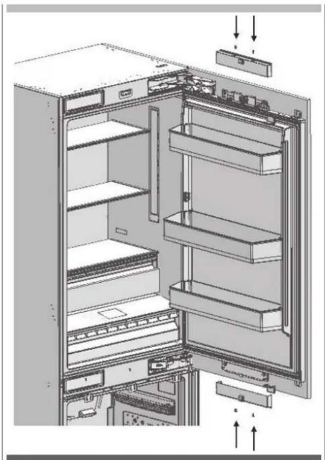
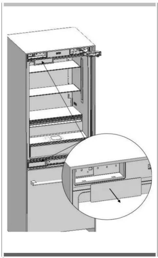
3D diagram of a refrigerator interior showing door, drawer, and shelf with internal components and directional arrows (no text or symbols)Removing the Lower Vent Hole Assembly
- Remove the 2 screws to take out the Lower Vent Hole Assembly.
natural_image
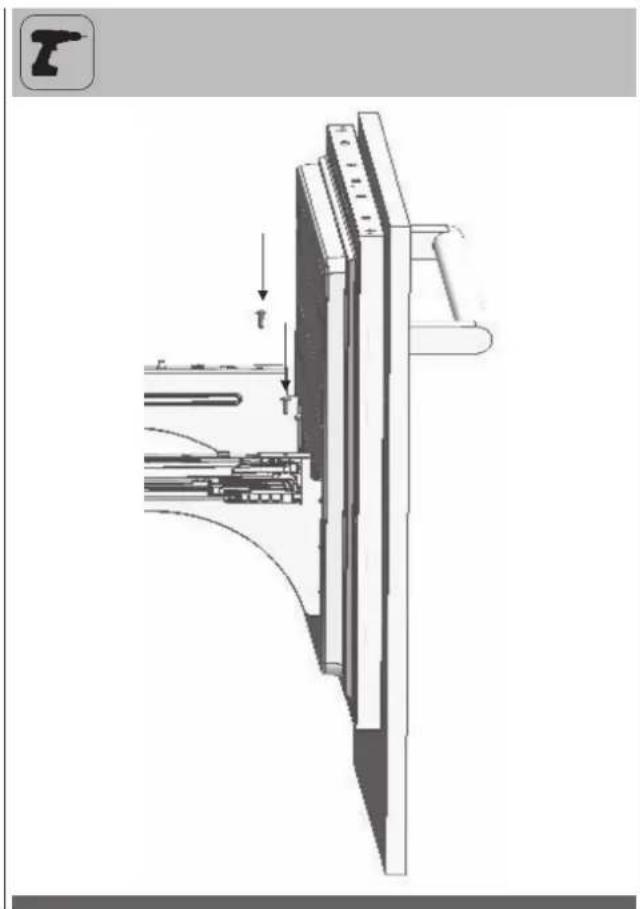
Technical line drawing of a mechanical assembly with mounting base and internal components (no text or symbols)Removing the Upper Vent Hole Part
- Remove the 2 screws to take out the Upper Vent Hole Part.
natural_image
Technical line drawing of a mechanical assembly with mounting base and structural components (no text or symbols)Continue to install the product according to the instructions below. Additionally, consider national and local instructions regarding installation.
Mounting the Anti-Tip Brackets

WARNING
You must definitely use Anti-Tip Brackets to prevent the appliance from tipping over.
Make sure that there is no electrical or water connection where the screws will be tighten and connections will be established.
Please remember to use the necessary protective equipment when drilling holes on the wall and performing installation.
• Mark the wall for Anti-Tip Brackets (7).
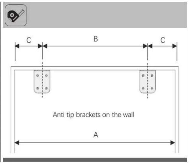
FBCD 761 TNF EDBL FBCD 762 TNF EDBL
A 762mm (30")
B 600mm (23 5/8")
C 81mm (3 3/16")
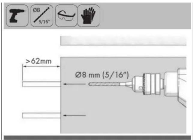
- Use a drill to creat holes for dowels 8) at the marked points. (∅8 mm - 5/16").
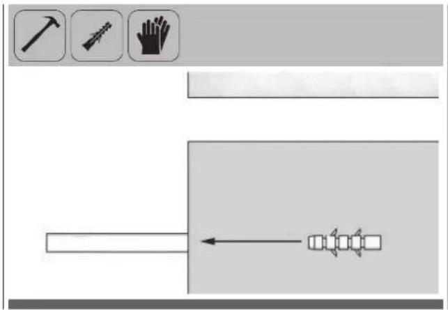
• Use the hammer to fit the dowels (8).
- Fit the brackets (7) into their places, using 4 screws for each. You must use all of the 2 brackets to ensure safety of the product.

WARNING
If you are not sure whether the existing connection parts are fit to the wall as securely as they should be, you can use alternative anti-tip methods.
If there is furniture at the back wall of the refrigerator, please make sure that the furniture is fixed to the wall. For this, you need to be sure that the back wall of the furniture is fixed to the concrete back wall with suitable connection parts.
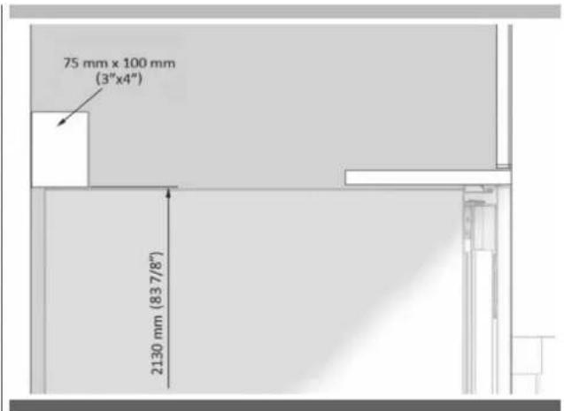
Alternative anti-tip method
If the anti-tip brackets cannot be connected securely, you must use the alternative method below.
In this method, you can use wooden girders to avoid the risk of tipping over.
It must be installed as illustrated in the figure below.
There must be no clearance between the product and the wooden girder.
Minimum section dimensions of the wooden girder must be 75mm x 100mm (3"x4"). Width of the girder must be equal to the clearance where it will be installed.
An additional girder must be used if the niche depth is more than anticipated. The wooden girder must contact the product with a maximum size of 50.8 mm (2").
To determine the location for the wooden girder, mark it on the rear wall, select suitable screws and connect safely.

WARNING
Number and features of the screws to be used for the wooden girder must be determined so that there is no safe connection.
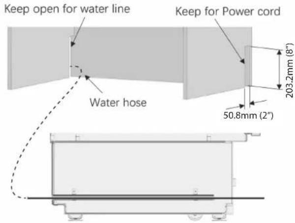
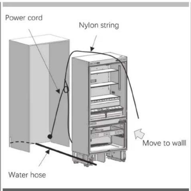
Preparing the Water Hose and the Power Plug
You will need a hose with a minimum length of 1.5 meters (60") and a diameter of 1/4" for water connections of the product during installation.
A connector that has a thread with an external diameter of 1/4 must be used to connect the hose end to the product. You can choose the method A or method B below to prevent the cable from getting jammed.
Method A: Locate the water hose and power supply on the back
Method B: Locate the water hose and power supply on the side
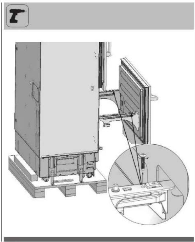
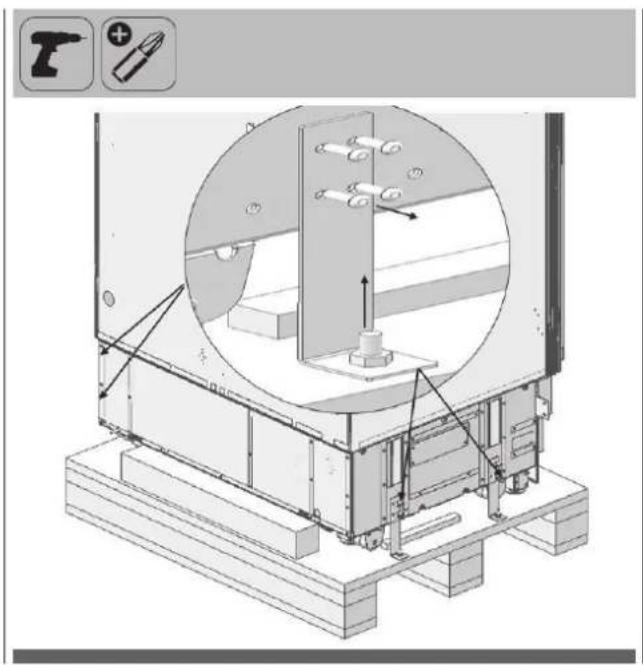
Taking the Refrigerator from the Wooden Pallet
- Remove the brackets that connect the refrigerator to the Wooden Pallet.
natural_image
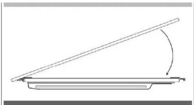
Technical illustration of a mechanical assembly with labeled components and directional arrows (no readable text or symbols)- Recline the refrigerator slowly and pull back with the help of the cart, and then land it.
natural_image
Technical illustration of a mechanical device with a handrail and a vertical panel, showing a directional arrow (no text or symbols present)
ATTENTION
The risk of tipping over is high as of this point. You should not open the doors until the product is placed into the cabin.
Placing the refrigerator into the cabin
- Insert the mains water hose into the duct at the back and take it out from the front.

natural_image
Technical illustration of a server rack with cable routing and a close-up inset showing internal components (no text or symbols)
IMPORTANT INFORMATION
- Apply the below method to prevent the cable from getting jammed.
- Start the refrigerator and make sure it is energised. (You can check if the lamps of the freezer compartment are on or off to see if the product is operating).

IMPORTANT INFORMATION
You can use tape and similar protectors on parts you think this is necessary to protect the edges of the furniture when placing the product.

WARNING
The plug of the product must be accessible after installation. If the plug is not accessible after installation, the power must be cut off from the main switch.
Make sure that the mains cable is not jammed when placing the product.
- Push the product carefully towards the cabin to place it. If there is strain during the placement of the product into the cabin:
- The floor might be rough or uneven
- Adjustable feet might be loose (please see the relevant section to learn how to adjust the adjustable feet)
- You must attach the Freezer Door temporarily to align the product before placing it.
You must use the upper edges of the Freezer Door when aligning the product with the furniture. Adjustment of other edges are explained in the following pages.

IMPORTANT INFORMATION
You must use the upper edges of the Freezer Door when aligning the product with the furniture.
Adjustment of other edges are explained in the following pages.
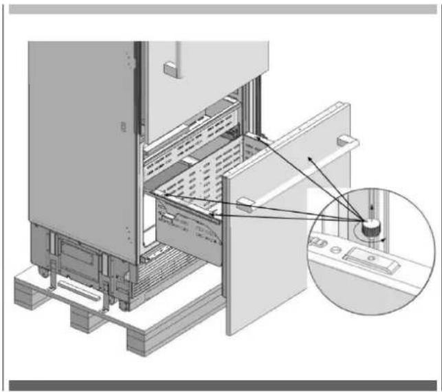
Adjusting the height of the refrigerator in the cabin
- Adjust the refrigerator height using the adjustable feet.
natural_image
Two black-and-white icons: a pencil and a screwdriver, both without any text or symbols.
WARNING
First of all, raise the front feet to reduce the risk of the cabin falling frontward.
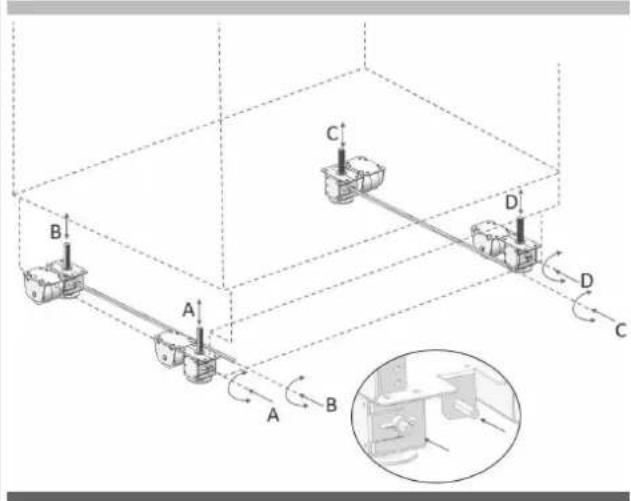
A/D -Turn the key clockwise to lift the front B/C -Turn the key clockwise to lift the rear
- After adjusting the adjustable feet, check the flatness in both width and depth directions.
natural_image
Interior view of a refrigerated industrial machine with visible internal components and no text or symbolsThe maximum height that the adjustable feet can reach is 40 mm (1 9/16") and the product height is 2169 mm (85 3/8").

IMPORTANT INFORMATION
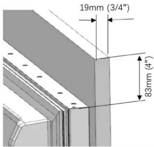
Adjusting the refrigerator according to the cabin flange
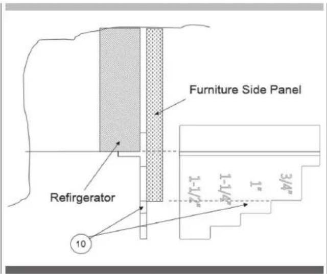
- For products with clad doors, the position of the Refrigerator is adjusted so that the door and the furniture surface are flush. You can also use gage (Item No10) if necessary.
natural_image
Technical line drawing of a cabinet with internal components and an inset magnified view showing internal structure (no text or symbols)- For products without clad doors, the product is placed using the Adjustment part (Item No10) as shown in the figure below.

IMPORTANT INFORMATION
It is very important to align the upper edge of the Freezer door when aligning. All the other edges can be adjusted with the adjustment mechanisms.
- Position of the level adjustment part (10) must be adjusted according to the thickness of the door. It can adjust the level for 4 different door thickness levels.
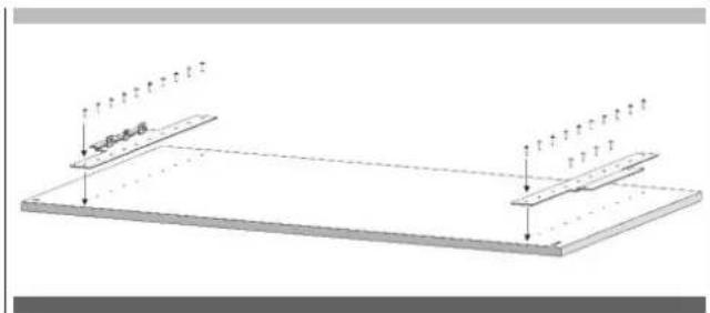
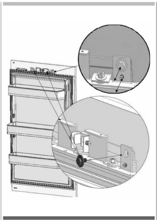
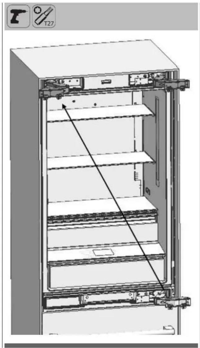
Screwing the side brackets
- Attach the Side Brackets to the furniture with 12 screws (Item No11) for each bracket.
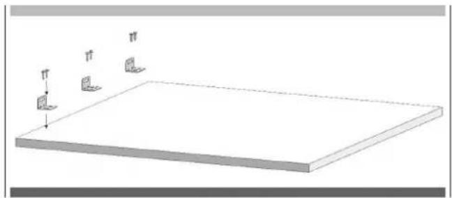
- Fix the brackets (Item No17) to the unit, where 2 on the top, and 3 on every side. Use the screws (Item No18) to tighten.
- Use the 12 long screws(Item No16) to join the product and the cabinet.

WARNING
Before starting to screw the Side and Upper brackets, please make sure that water is supplied to the product and there is no water leakage (only for model FBCD 762 TNF EDBL).
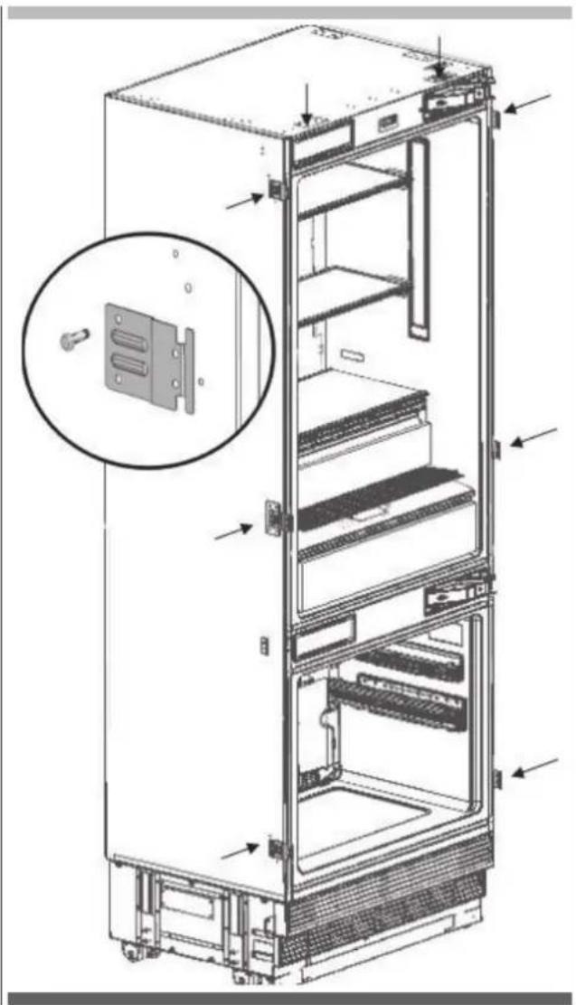
natural_image
Technical line drawing of an open refrigerator with internal compartments and a close-up inset showing the door panel (no text or symbols present)
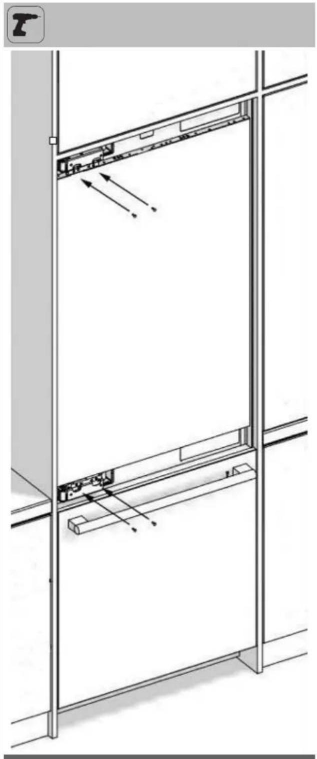
IMPORTANT INFORMATION
If you have difficulty tightening the screws, opening a reference hole with the drill will make this procedure easier.

natural_image
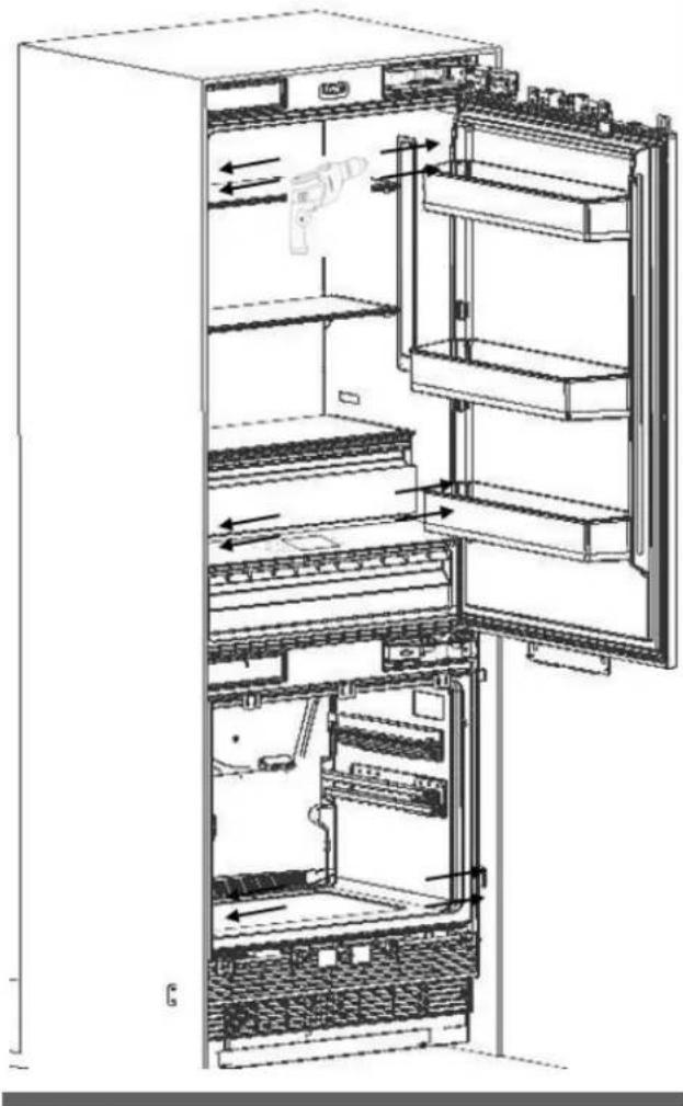
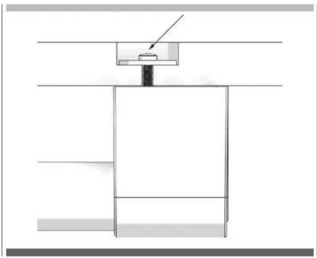
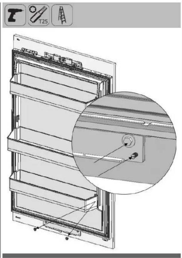
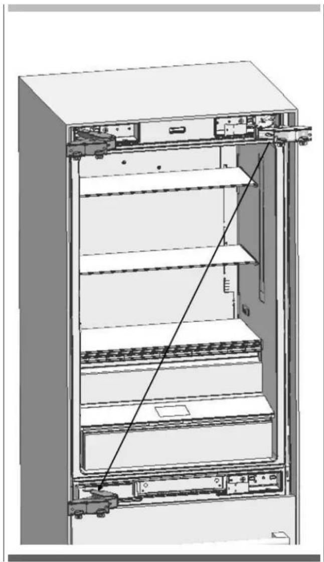
Interior view of a refrigerator showing open doors, shelves, and internal compartments with arrows indicating flow direction (no text or symbols)Screwing the upper bracket
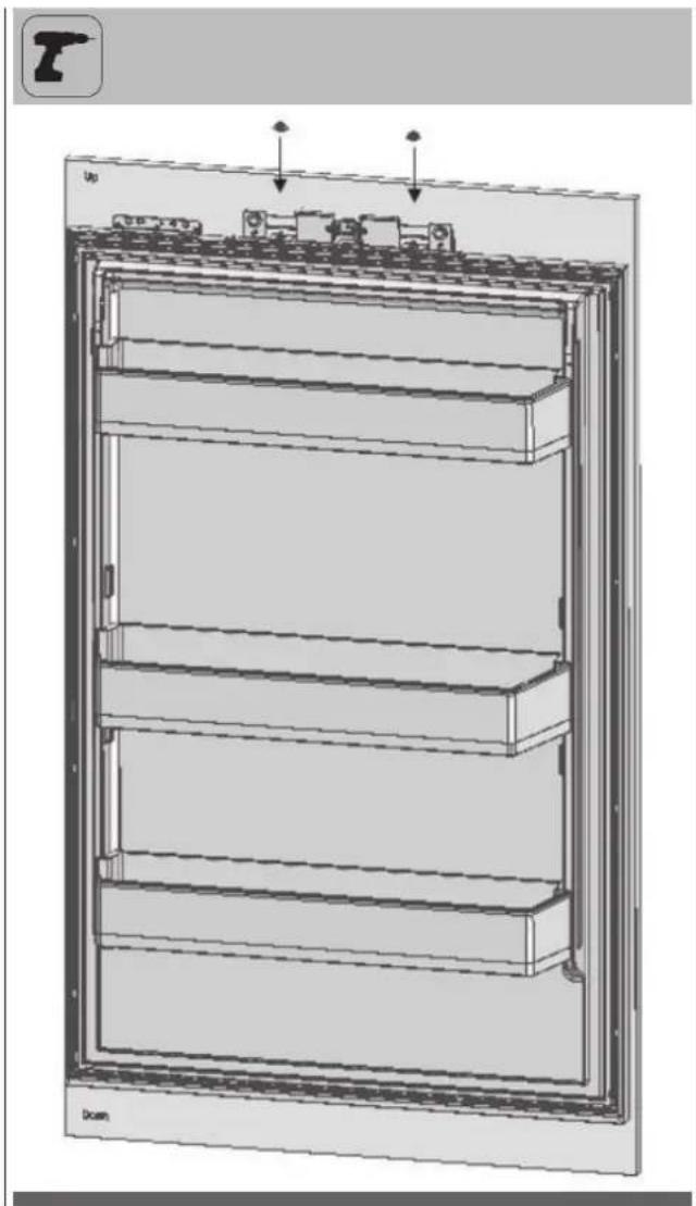
- Attach the upper bracket to the furniture with 4 screws (Item No16).

IMPORTANT INFORMATION
If you have difficulty tightening the screws, opening a reference hole with the drill will make this procedure easier
natural_image
Line drawing of a refrigerator interior showing front and rear compartments with no text or symbolsWater connection
- Use the box cutter to cut the water hose from the end of the pipe it comes out, leaving a section of 10".
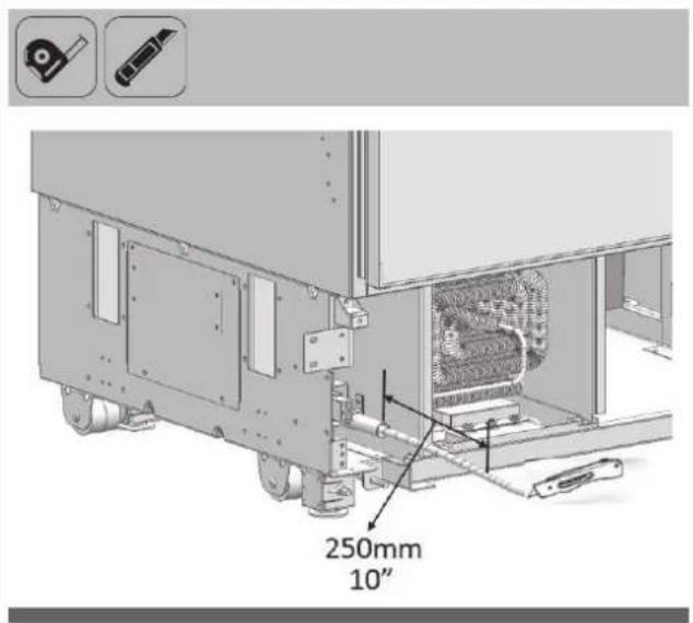
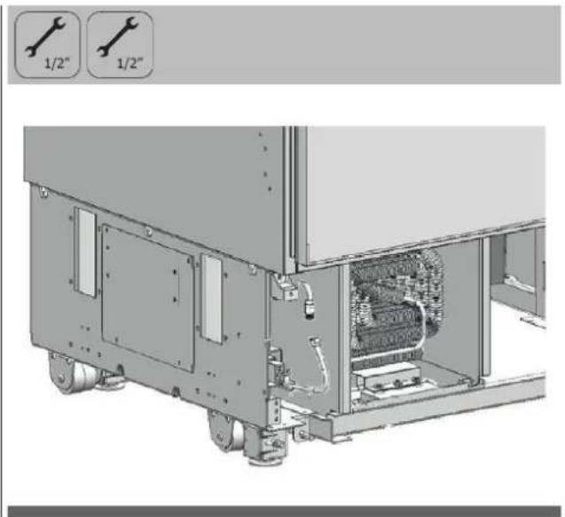
- Use the 2 wrenches to firmly connect the hose coming from the mains and the hose coming from the valve.

WARNING
The hose coming from the mains must be one piece. Do not use extension hoses.
Make sure that the power is cut off when making the water connection of the product.
The water valve must be off when connecting the water hose.
It is recommended that the water on/off valve remains accessible after installing the product.
This product is suitable for use with cold water mains only.
Pressure of the water system must be between 25-80 psi (1.7-5.5 Bar).

IMPORTANT INFORMATION
Once the connection is complete, you must turn on the mains valve and make sure that there is no leakage at that point.
natural_image
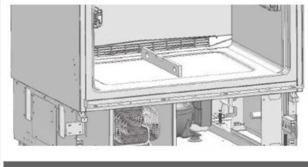
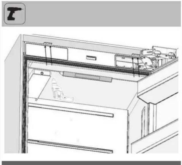
Technical illustration of an industrial machine with two wrench icons labeled '1/2" (no text or symbols on the diagram itself)Attaching the upper vent hole part
• Use 2 screws to attach the upper vent hole part.
natural_image
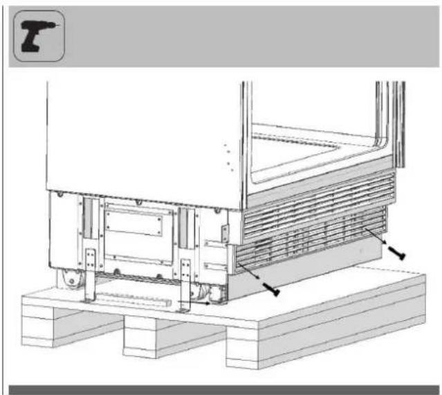
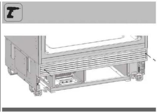
Technical line drawing of a mechanical assembly with no visible text or symbolsAttaching the lower vent hole assembly
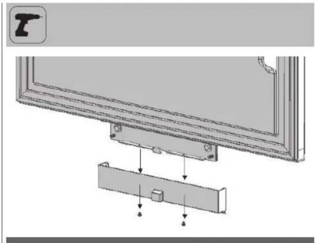
• Use 2 screws to attach the lower vent hole part.
natural_image
Technical illustration of a refrigerated kitchen unit with ventilation grilles and a door (no text or symbols)
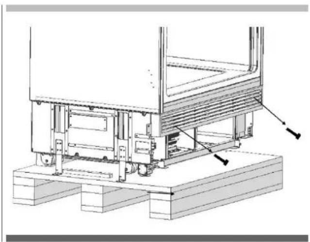
IMPORTANT INFORMATION
You can move the lower vent hole forward-backward to adjust it to the kick plate in the kitchen.

WARNING
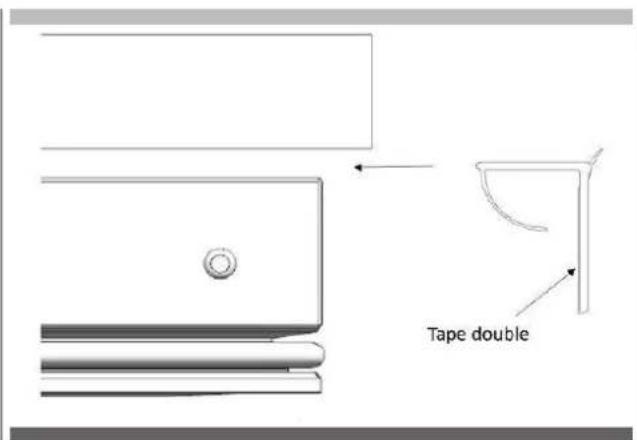
Forward-backward travel distance of the lower kick plate must be 23 mm (15/16"). As you can see in the figure, the decorative kick plate must not be in front of the upper vent hole level.
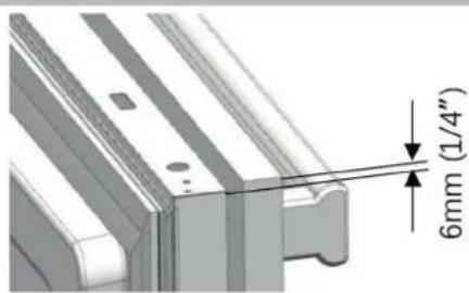
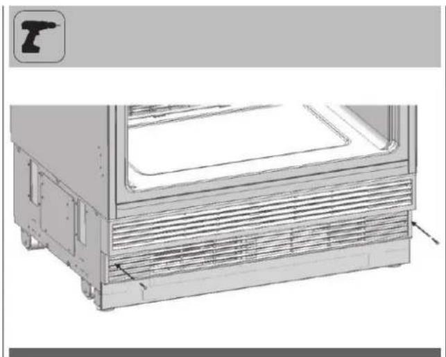
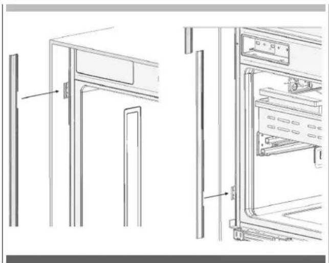
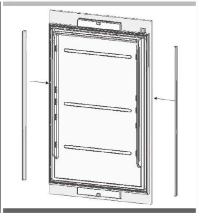
Attaching the decorative parts
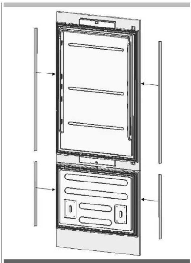
- Attach the side closing parts (1) onto the right/left connection brackets.
natural_image
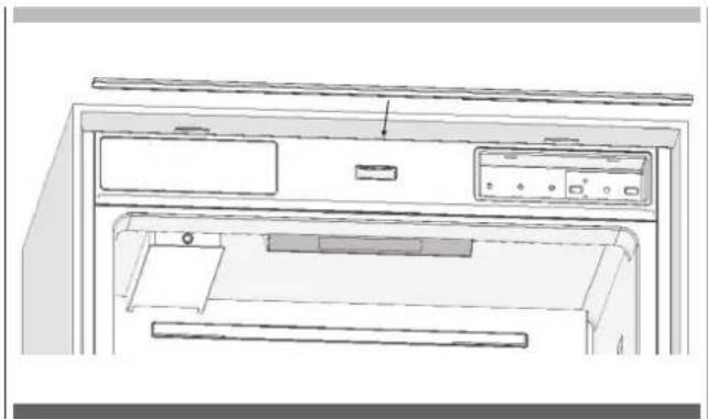
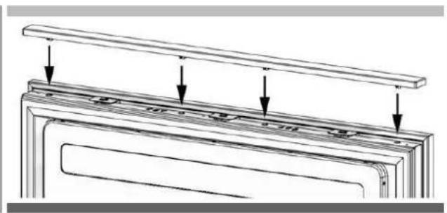
Technical line drawing of a refrigerator interior showing front and side views (no text or symbols)- Attach the upper closing part (4) onto the upper connection bracket.
natural_image
Line drawing of a front view of a computer oven with ventilation slots and control panel (no text or symbols)EN FURNITURE DOOR PREPARATION
This section contains information about preparing the furniture doors and mounting them to the product.

WARNING
Maximum weights of the furniture to be mounted to the product are as follows.
Fridge Door: 16.2 kg (35.7 lbs.)
Freezer Door: 9 kg (19.8 lbs.)
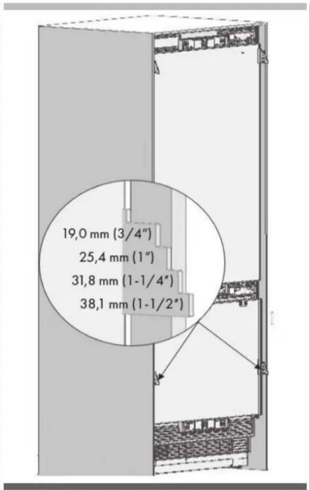
Choosing the Door Thickness
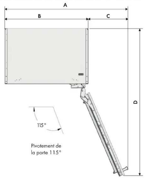
- The door of your refrigerator can open by 115° maximum. If the door is going to open to this degree, you can choose the following thickness levels.

WARNING
If the door thickness is more than 38 mm (1 ½"), the door should not open more than 90°. You must use a limiting pin on the hinge.
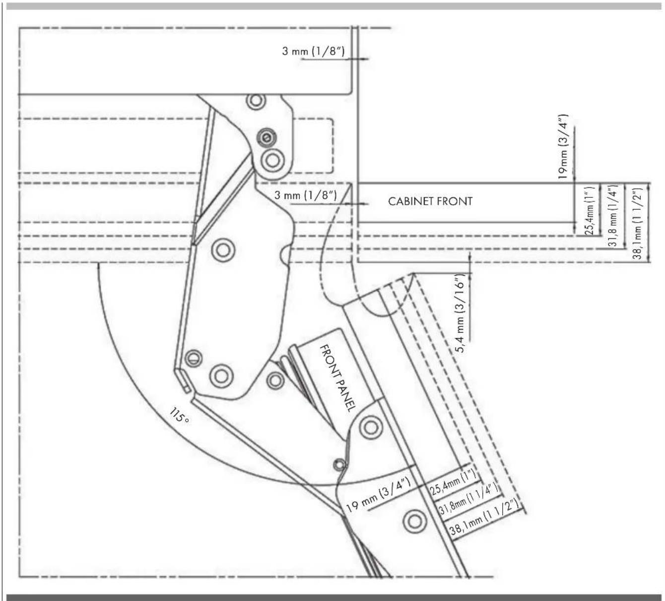
- You can limit the opening degree of your door to 90° if you want.
In this case, the door thickness levels can be like the following (you can look at the relevant section to learn how to attach the 90° limiting pin.
![3mm (1/8") 19mm 83/4" 25,4mm [1"] 31,8mm [1 1/4"] 38,1mm [1 1/2"] CABINET FRONT FRONT PANEL 19mm (3/4") 25,4mm [1"] 31,8mm [1 1/4"] 38,1mm [1 1/2"]](/content/2026/04/598949/images/20f0b36c20b174d4d2ad679583b91e073b166d3ece7dba14649620903420c0df.jpg)
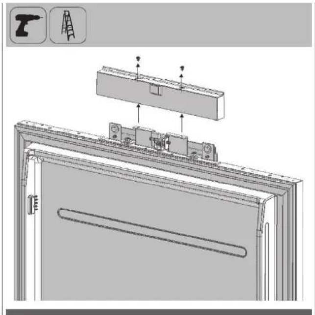
Removing the Mechanism Covers
- Remove one screw to take out the FF Upper Cover.
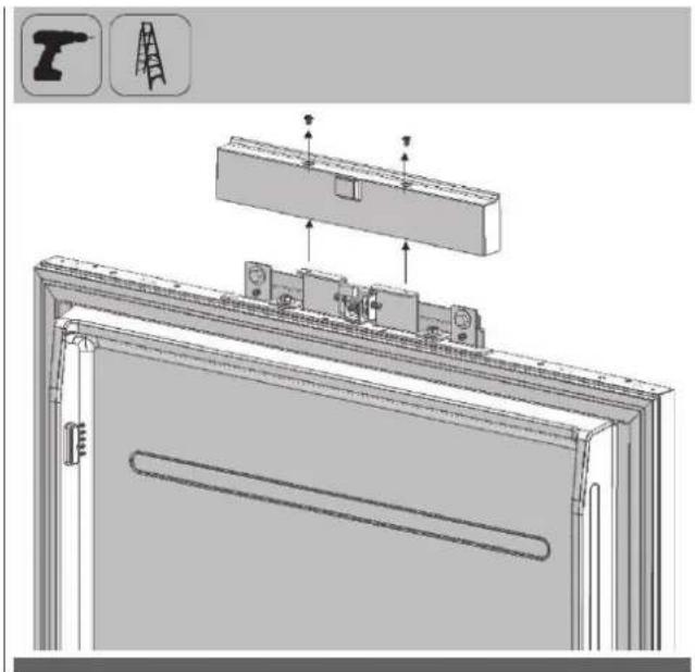

WARNING
There is a magnet on the cover door hanger bracket. This is a functional part for the operation of the product. It should not be confused with the lower cover.
- Remove two screws to take out the cover door hanger bracket.
natural_image
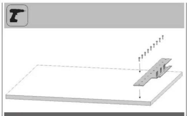
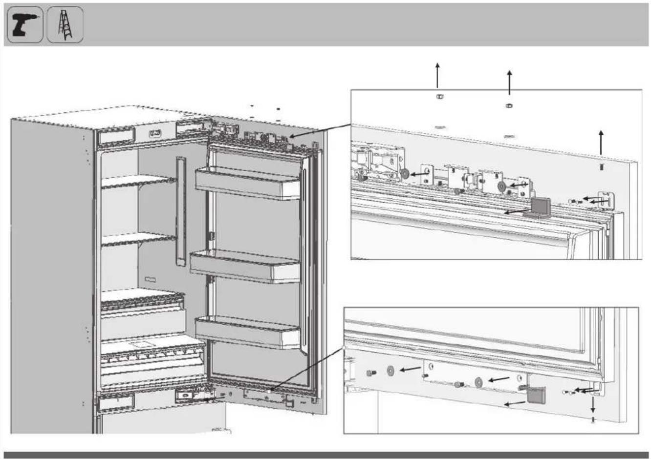
Technical diagram showing a bracket assembly with mounting holes and a tool icon (no text or symbols)Removing the Panel-Adjustment Mechanisms on the Refrigerator
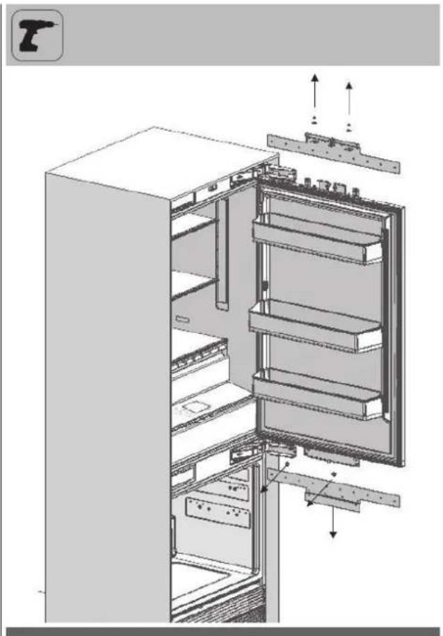
- Remove the Upper and Lower Adjusting Mechanism Assemblies from the FF Door.
natural_image
Technical illustration of an open refrigerator with internal compartments and mounting hardware (no text or symbols)- Remove the Panel-Adjustment Mechanisms from the lower part of the freezer Door.
natural_image
Technical illustration of a mechanical assembly with cutouts and mounting brackets (no text or symbols)Preparing Furniture Door

IMPORTANT INFORMATION
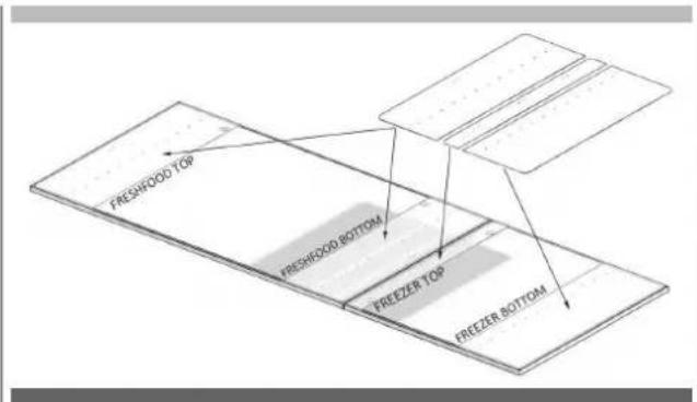
You must take the dimensions into account when grouping the cradle parts on the furniture door. When marking, you can use the "Furniture door preparation template" (Item No 6) provided with the product.

WARNING
Handle connection holes must be adjusted according to the handles to be used in kitchen design.
Minimum thickness of the door must be 19mm (3/4").
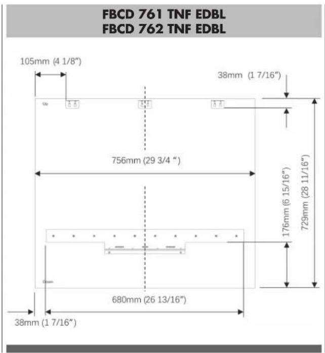
Preparing the Fridge Furniture Door
FBCD 761 TNF EDBL FBCD 762 TNF EDBL
A 756mm (29 3/4")
B 38mm (17/16")

WARNING
You must use screws suitable for the door thickness.
- Install 2 cradles using the chipboard screws (Item No23). You can also use the template (Item No 6) provided with the product to align these parts. It is recommended to keep this template for future reference.
natural_image
Pure technical diagram of a rectangular plate with two horizontal supports and directional arrows, no text or symbols present.- Attach the FRZ door handle. Screws holding the door handle must not protrude
natural_image
Pure technical diagram of a mechanical assembly with no text, numbers, or symbolsPreparing the Freezer Furniture Door

WARNING
Handle connection holes must be adjusted according to the handles to be used in kitchen design.
Minimum thickness of the door must be 19 mm (3/4").
You must use screws suitable for the door thickness.
- Install 1 cradle using the chipboard screws (Item No23). You can also use the template (Item No 6) provided with the product to align these parts. It is recommended to keep this template for future reference.
natural_image
Diagram showing a mechanical assembly with a tool and a bracket, no text or symbols present- Attach 3 sheet metal brackets (Item No14) using 6 screws (Item No15) for each.
natural_image
Simple 3D diagram of a rectangular plate with three small L-shaped cutouts and a downward arrow, no text or symbols present.- Attach the FRZ door handle. Screws holding the door handle must not protrude
natural_image
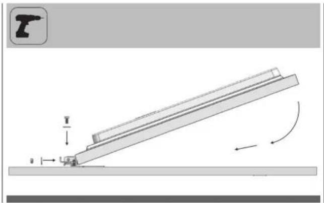
Pure technical diagram of a mechanical assembly with no text, numbers, or symbols- Lay down the furniture door, and place the freezer door onto it
- Put the screws back but do not tighten
natural_image
Diagram of a lever system with a fulcrum and rotating motion arrows (no text or symbols)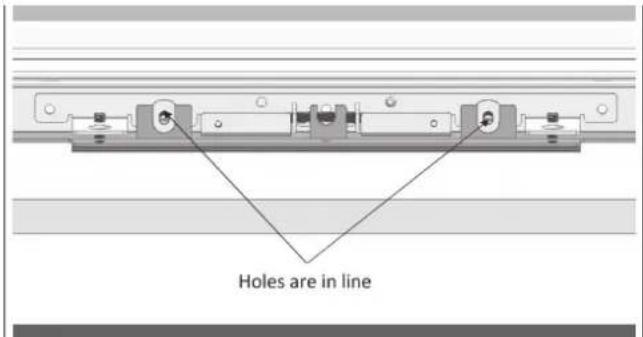
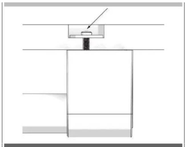
- Use the 3 screws (Item No13) to fix the bracket. the washers(Item No12) are provided in case of need.
- Tighen the screws once the furniture door and the freezer door is perfectly attached.
natural_image
Technical diagram of a mechanical assembly with two vertical supports and directional arrows indicating movement (no text or symbols present)A total of 3 mm washers must be placed on the FRZ Door on the condition that all furniture dimensions are suitable.
Washers to be used are determined based on the kitchen design.

WARNING
You will find more Crescent Washers than you need in the mounting box. You can use them if your kitchen design requires so.
Installing the Fridge Furniture Door
Attach the furniture door to the fridge door.
natural_image
Simple line drawing of a triangular ruler with an arrow indicating rotation (no text or symbols)- Use the two screws removed from here to fix onto the adjusting bolts
natural_image
Technical line drawing of a multi-level rack cabinet or enclosure with mounting brackets and top panel (no text or symbols)EN
- Adjust from lower part of the door with 2 screws removed from here together with 2 slotted screws.
- Use the bracket (Item No21) to join the furniture door and fridge door, use 2 screws (Item No20) and 1 screw (Item No22) to fix.
natural_image
Technical diagram of an electrical enclosure with internal components and a magnified inset showing a component detail (no text or symbols present)- Adjust from lower part of the door with 2 screws removed from here together with 2 slotted screws.
- Use the bracket (Item No21) to join the furniture door and fridge door, use 2 screws (Item No20) and 1 screw (Item No22) to fix.
natural_image
Technical line drawing of a refrigerator with an inset close-up showing internal components (no text or symbols)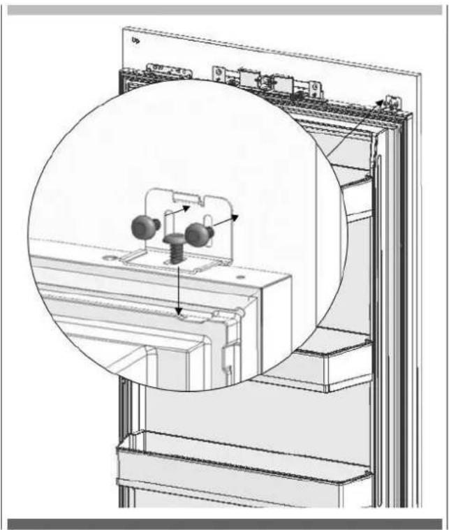
natural_image
Technical diagram of a mechanical assembly with a magnified inset showing internal components (no text or symbols)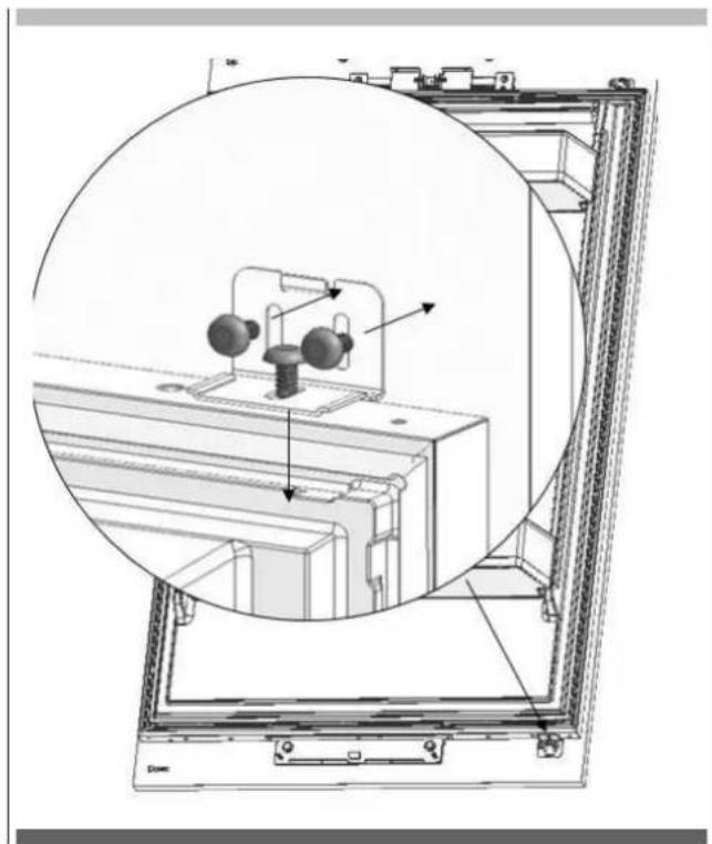
natural_image
Technical diagram of a mechanical assembly with a circular cross-section view showing internal components (no text or labels)- Clip the decoration cover (Item No19)
natural_image
Interior view of a refrigerator showing open doors and internal compartments, with an inset close-up highlighting the exterior panel (no text or symbols visible)- Use the 4 screws removed from here to fix the upper/lower decoration cover.
natural_image
Interior view of a refrigerator showing open doors, shelves, and doorways (no text or labels)
WARNING
You must keep these parts for future use. You will need them if you want to change the door directions.
Installing the Freezer Furniture Door
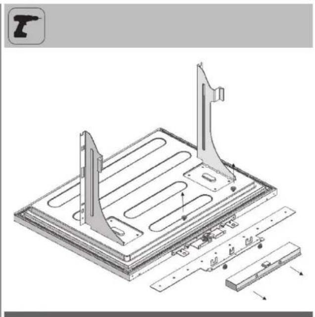
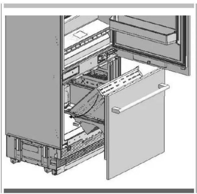
• Install the Freezer Furniture door assembly onto the rails.
natural_image
Technical diagram showing a mechanical assembly with an inset close-up of a tool interacting with a component (no text or symbols present)- Fix the Freezer Furniture door assembly onto the rails with 2 screws.
natural_image
Technical diagram of a mechanical assembly with a bracket and mounting base, showing structural components and motion direction (no text or symbols)- Locate the drawer onto the rail and tigthen the screws.
natural_image
3D technical illustration of an internal storage or processing unit with labeled compartments and internal components (no text or symbols)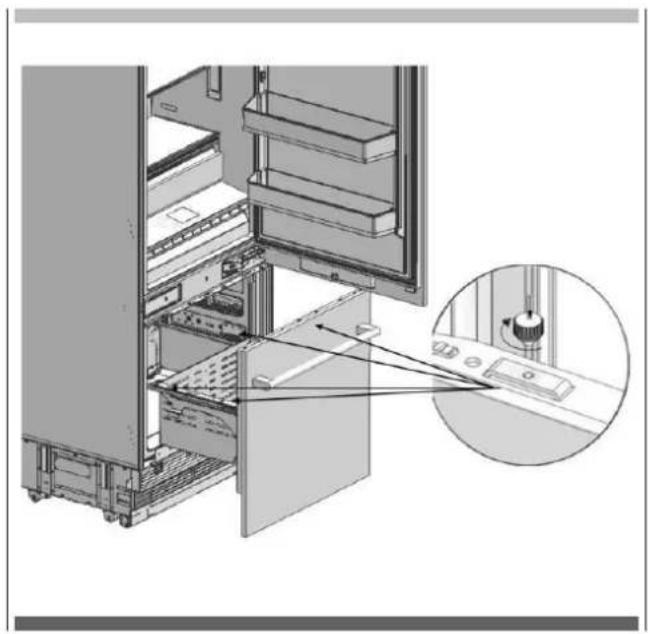
natural_image
Technical diagram of a server rack with an inset close-up showing internal components (no text or symbols)If need to adjust the Furniture Doors, and the operating principle of the mechanisms are shown below.
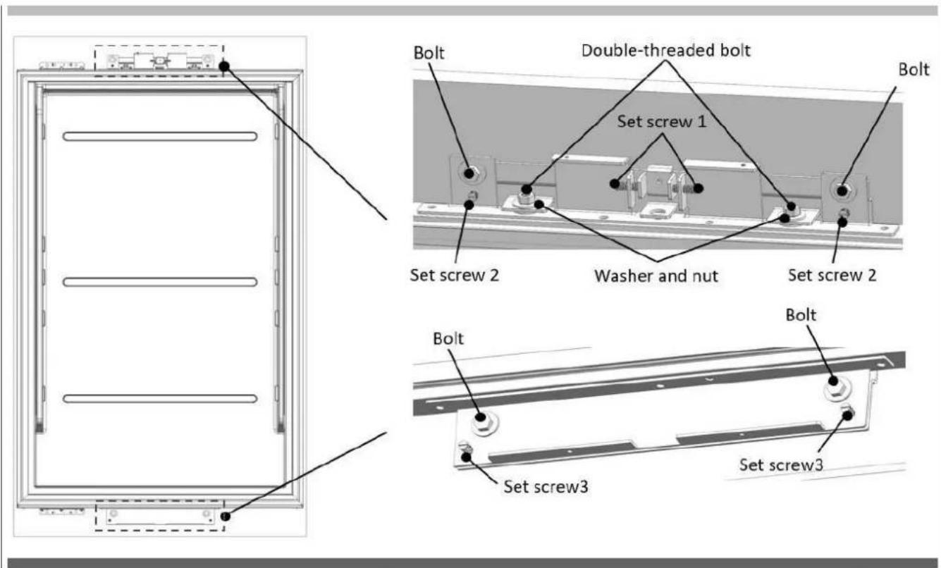
Panel-adjustment for fridge door
- Use the double-threaded bolts to align the door panel
- Engage set screw1 (see the graphic) to shift the panel side to side.
- Engage set screw2 (see the graphic) to shift the panel forward/backward; engage bolt to set the panel top part in place.
- Engage set screw3 (see the graphic) to shift the panel forward/backward; engage bolt to set the panel lower part in place.
- Engage fixing washer and nut to set the panel in place.
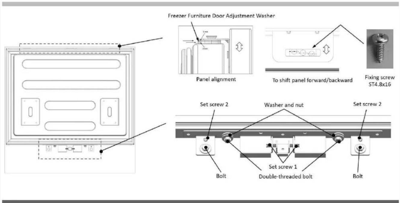
Panel-adjustment for fridge door
- Use the freezer furniture door adjustment washer to align the door panel top part.
- Engage set screw1 (see the graphic) to shift the panel side to side.
- Select fixing hole (see the graphic) to shift the panel forward/backward; engage fixing screw to set the panel in place.
- Engage set screw2 (see the graphic) to shift the panel forward/backward; engage bolt to set the panel in place.
- Engage the double-threaded bolts fixing the door panel lower part.
- Engage washer and nut fixing the panel lower part in place.
- Attach the FRZ Cover (5) using the tabs.
- Attach the side closing seals (2) (3).
natural_image
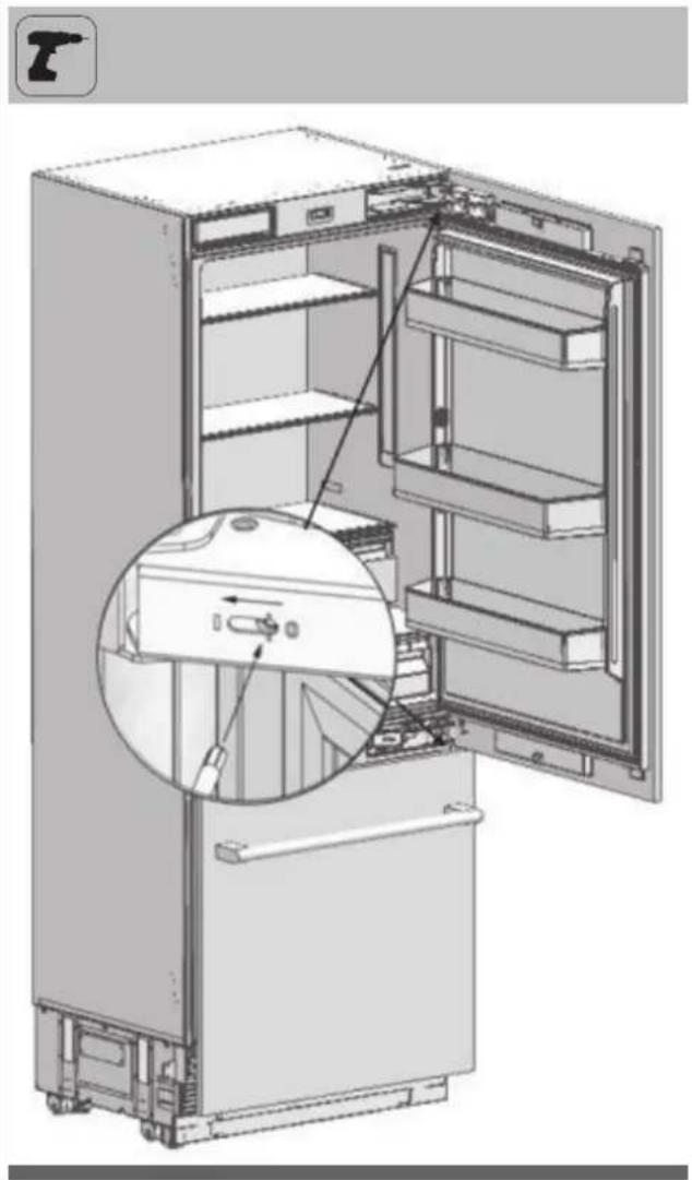
Technical line drawing of a refrigerator panel with door, vent, and side panels (no text or symbols)Adjusting the hardness of the hinges
- Use a drill to adjust the hardness of the upper and lower hinges f the FF Door. Set the hinge adjustment screw to position "I" from position "O".
natural_image
Interior view of a refrigerator showing open doors and internal shelves, with a magnified inset highlighting the interior portion (no text or symbols visible)
WARNING
The door must be fully open during this adjustment.
This adjustment must definitely be performed after the door has been adjusted.
Removing the FF clad door
- Set the hardness level of the hinge to "0".
natural_image
Diagram of an open refrigerator showing internal shelves and door, with a magnified inset highlighting the interior structure (no text or symbols present)
WARNING
Failure to set the hinge to "0" and continuing the installation like that may cause injury.
- Remove the side closing seals.
natural_image
Technical line drawing of a door frame with two vertical supports and horizontal bars, no text or symbols present- Loosen 2 screws of the Upper Cover of the Fridge Door and remove it.
- Remove the upper adjustment kits
natural_image
Technical diagram of a door frame assembly with mounting bracket and control panel (no text or symbols)- Loosen 2 screws of the Lower Cover of the Fridge Door and remove it.
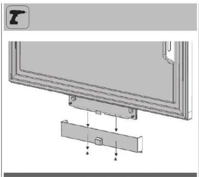
natural_image
Diagram of a device mounting bracket with arrows indicating assembly or adjustment (no text or symbols present)- Remove FF Lower and Upper Bracket screws.
- Remove the screw of FF Upper and Lower mechanisms.

WARNING
The clad door will be released when these screws are removed.
You must take measures to prevent the door from falling.
You can tape the Furniture Door to the Inner Door or ask for help from another person.
• Take the Fridge Furniture Door and lay it down on a table upside down.
- You must attach the Furniture Door by rotating it 180° based on its current position.
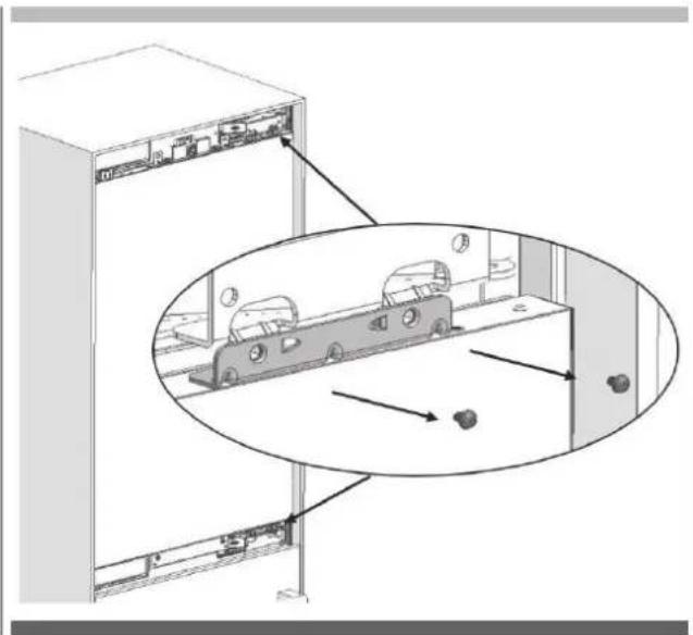
Removing and preparing the Fridge Inner Door
- Remove the hinge connection screws of the Hinge Brackets.

WARNING
The clad door will be released when these screws are removed.
You must take measures to prevent the door from falling. You can tape the Furniture Door to the Inner Door or ask for help from another person.
natural_image
Diagram showing a server rack with a close-up of a mechanical component, no text or symbols present- Take out the FF Door and lay it down on a table remove the fixing parts and screw them to the opposite side of the door.
• Take out fridge door and lay it down on a table. - Remove the hinge brackets on the fridge door and screw them as shown figure.

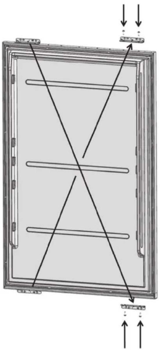
Replacing the hinges
- Remove the Hinge Caps located at the other side where you will fix the hinges.
natural_image
Diagram of an open refrigerator showing internal compartments and a close-up view of the interior (no text or labels)- Remove the lower right hinge by loosening its 2 screws and fix it to its slot at the upper Leftside.
- Remove the upper right hinge by loosening its 2 screws and fix it to its slot at the lower Left side
- Attach the Hinge Slot Caps removed from the left side to the Hinge Caps at the right side.
natural_image
Technical line drawing of an open refrigerator with visible door, shelves, and internal components (no text or symbols)
natural_image
Technical illustration of an open refrigerator with a close-up inset showing internal components (no text or symbols)Installing the FF PU Door
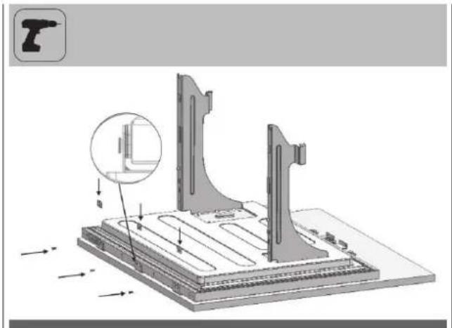
- Place the Fridge Inner Door to the refrigerator and fix it with 4 screws.
natural_image
Technical line drawing of a structural frame with internal components and directional arrows (no text or symbols)INDICE
PAGE
Lieu d'installation


AVERTISSEMENT
natural_image
3D line drawing of a cabinet with open door and side door, no text or symbols presentnatural_image
Technical line drawing of a refrigerator interior showing front and side views with dimension label A (no text or symbols present)FBCD 761 TNF EDBL FBCD 762 TNF EDBL
A 824mm (32 7/16")
B 756mm (29 3/4")
C 1398mm (55 1/32")
FBCD 761 TNF EDBL FBCD 762 TNF EDBL
A 1127mm (443/8")
B 756mm (29 3/4")
C 371mm (14 5/8")
D 1338mm (52 11/16")
Installation du support anti-basculement
FBCD 761 TNF EDBL
FBCD 762 TNF EDBL
natural_image
Three black-and-white icons showing a push truck, a worker in hard hat, and an overalls (no text or symbols)natural_image
3D line drawing of a rectangular cabinet or enclosure with three vertical panels and horizontal supports (no text or symbols)natural_image
Exploded view diagram of a server rack unit with internal components and mounting brackets (no text or labels)
ATTENTION
natural_image
Technical illustration of a server rack with an open door and internal compartments, showing a close-up inset (no text or symbols)natural_image
3D technical illustration of a mechanical device with internal components and mounting base (no visible text or symbols)natural_image
Technical illustration of a mechanical assembly with an inset close-up showing a component detail (no text or symbols present)natural_image
Diagram of a refrigerator interior showing door, drawer, and shelf with an inset close-up of the tray (no text or symbols)natural_image
Technical diagram of a mechanical assembly with mounting base and internal components (no text or symbols)natural_image
Technical line drawing of a mechanical assembly with mounting base and structural components (no text or symbols)natural_image
Technical illustration of a mechanical assembly with circular components and mounting base (no text or symbols)natural_image
Technical illustration of a mechanical device with a handrail and a vertical panel, showing a directional arrow (no text or symbols present)
ATTENTION
natural_image
Technical illustration of a server rack with cable routing and a close-up inset showing internal components (no text or symbols)
INFORMATIONS IMPORTANTES
natural_image
Two black-and-white icons: a pair of a drill pen and a screwdriver with hexagonal nut, both enclosed in rounded square frames (no text or symbols)
AVERTISSEMENT
natural_image
Technical line drawing of an internal machine or enclosure with no visible text or symbolsnatural_image
Technical line drawing of a cabinet with an inset showing internal components (no text or symbols)natural_image
Technical line drawing of an internal refrigerator with a close-up inset showing the door panel (no text or symbols present)
INFORMATIONS IMPORTANTES
natural_image
Interior view of a refrigerator showing open doors, shelves, and internal compartments with arrows indicating flow direction (no text or symbols)natural_image
Line drawing of a refrigerator interior showing front and rear compartments with no text or symbolsFR INSTALLATION DU FOND DE LA CABINE
Raccordement d'eau
natural_image
Technical illustration of an industrial machine with two wrench icons and a close-up view of internal components (no text or symbols)natural_image
Technical line drawing of a mechanical device with internal components and mounting base (no text or symbols)natural_image
Technical line drawing of a refrigerated kitchen unit with ventilation grilles and a door (no text or symbols)
INFORMATIONS IMPORTANTES
natural_image
Technical line drawing of a refrigerator interior showing front and side views (no text or symbols)natural_image
Line drawing of a front view of a computer oven with control panel and door (no text or symbols)FR PRÉPARATION DES PORTES DU MEUBLE

AVERTISSEMENT
natural_image
Technical diagram showing a mechanical assembly with a bracket and mounting holes, no text or symbols present.natural_image
Technical illustration of an open refrigerator with internal compartments and mounting hardware (no text or symbols)natural_image
Technical illustration of a mechanical assembly with cutouts and mounting brackets (no text or symbols)natural_image
Pure technical diagram of a mechanical assembly with no text, numbers, or symbolsnatural_image
Diagram showing a mechanical assembly with a tool and a bracket, no text or symbols presentnatural_image
Simple 3D diagram of a rectangular plate with three small labeled components on its surface (no text or symbols)natural_image
Pure technical diagram of a mechanical assembly with no text, numbers, or symbolsnatural_image
Diagram of a mechanical lever system with motion arrows indicating rotational motion (no text or symbols)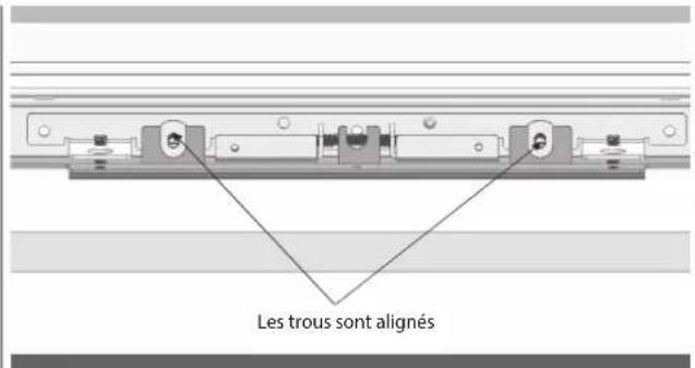
natural_image
Technical diagram of a mechanical assembly with directional arrows and a magnified inset showing internal components (no text or symbols)natural_image
Simple line drawing of a triangular structure with an arrow indicating rotation, no text or symbols present.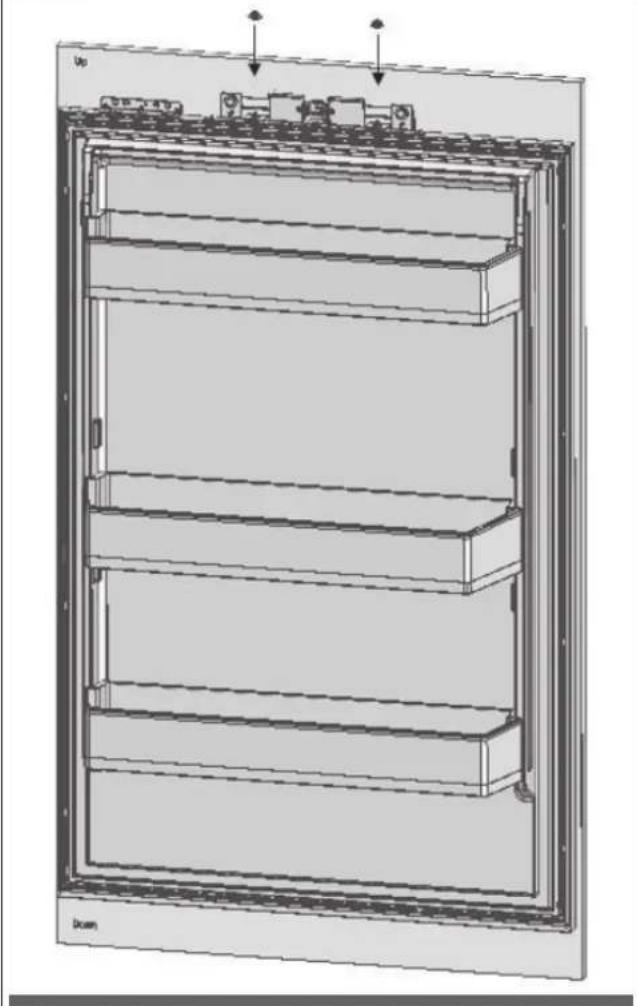
natural_image
Technical line drawing of a multi-tiered storage cabinet or rack unit with mounting brackets and ventilation slots (no text or symbols)FR
natural_image
Technical illustration of an electrical enclosure with internal components and a close-up inset showing a mechanical assembly (no text or symbols present)natural_image
Technical line drawing of a multi-tiered refrigerator with an inset close-up showing internal components (no text or symbols)
natural_image
Technical diagram of a mechanical assembly with an inset showing internal components (no text or symbols present)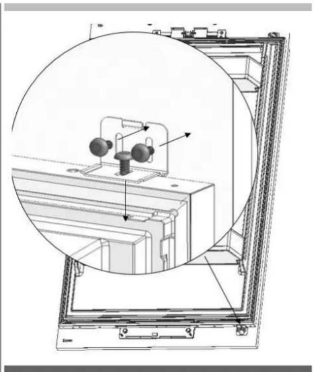
natural_image
Technical diagram of an electrical enclosure with internal components and a circular inset view (no text or symbols)natural_image
Interior view of a refrigerator showing open doors and internal compartments (no text or labels visible)natural_image
Interior view of a refrigerator showing open doors, shelves, and doorways (no text or labels)
AVERTISSEMENT
natural_image
Technical diagram showing a mechanical assembly with an inset close-up of a rotating component (no text or symbols present)natural_image
Technical diagram of a mechanical assembly with a tool and component, showing no text or symbols.natural_image
Interior view of a refrigerator with open door, showing internal compartments and storage racks (no text or symbols visible)
natural_image
Technical diagram of a server rack with an inset close-up showing internal components (no text or symbols)natural_image
Technical line drawing of a door frame with horizontal bars and arrows indicating assembly or measurement (no text or symbols)natural_image
Technical line drawing of a refrigerator interior with door, vent, and door panel (no text or symbols)FR RÉGLAGE DE LA CHARNIÈRE
natural_image
Interior view of a refrigerator showing open doors and internal shelves, with a magnified inset highlighting the interior portion (no text or symbols visible)
AVERTISSEMENT
natural_image
Diagram of an open refrigerator showing internal shelves and door, with a magnified inset highlighting the interior structure (no text or symbols present)
ATTENTION
natural_image
Technical line drawing of a door frame with two vertical supports and horizontal bars, no text or symbols presentnatural_image
Technical diagram of a door frame assembly with mounting bracket and control panel (no text or symbols)natural_image
Diagram of a device mounting bracket with arrows indicating assembly or adjustment (no text or symbols present)natural_image
Diagram showing a server rack with internal components and a magnified view of the rack structure (no text or symbols)natural_image
Diagram of an open refrigerator showing internal compartments and a close-up view of the interior (no text or labels)natural_image
Technical line drawing of an open refrigerator with visible internal compartments and mounting brackets (no text or symbols)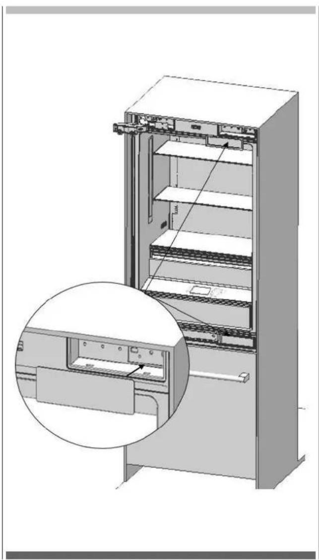
natural_image
Technical illustration of an open refrigerator with internal shelves and a close-up inset showing internal components (no text or symbols)natural_image
Technical line drawing of a cabinet or shelf assembly with internal components and directional arrows (no text or symbols)Alternative Kippschutzmethode: 18
Aufstellungsort


WARNUNG
natural_image
3D line drawing of a two-door cabinet with door, door, and door clamps (no text or symbols)Produktabmessungen
FBCD 761 TNF EDBL FBCD 762 TNF EDBL
A 756mm (29 3/4")
natural_image
Technical line drawing of an open refrigerator with labeled door and side panel (no text or symbols)FBCD 761 TNF EDBL FBCD 762 TNF EDBL
A 824mm (32 7/16")
B 756mm (29 3/4")
C 1398mm (55 1/32")

FBCD 761 TNF EDBL FBCD 762 TNF EDBL
A 1127mm (443/8")
B 756mm (29 3/4")
C 371mm (14 5/8")
D 1338mm (52 11/16")

FBCD 761 TNF EDBL
FBCD 762 TNF EDBL
natural_image
Three icons: a push truck, an overalls, and a person in hard hat (no text or symbols)natural_image
3D line drawing of a rectangular cabinet or enclosure with three vertical panels stacked vertically (no text or symbols)natural_image
Exploded view diagram of a server rack unit with internal components and mounting brackets (no text or labels)
ACHTUNG
natural_image
Technical illustration of an internal storage or rack system with a magnified inset showing a component detail (no text or symbols present)natural_image
3D technical illustration of a mechanical device with internal components and mounting base (no visible text or symbols)natural_image
Technical illustration of a mechanical assembly with an inset close-up showing a component detail (no text or symbols present)natural_image
Diagram of a refrigerator interior showing door, drawer, and shelf with an inset close-up of the tray (no text or symbols)natural_image
Technical line drawing of a mechanical assembly with mounting base and internal components (no text or symbols)natural_image
Technical diagram of a mechanical assembly with mounting base and structural components (no text or symbols)Alternative Kippschutzmethode:
natural_image
Technical illustration of a mechanical assembly with a circular component and supporting frame (no text or symbols)natural_image
Technical illustration of a mechanical device with a handrail and a vertical panel, showing a directional arrow (no text or symbols present)
ACHTUNG
natural_image
Technical illustration of a server rack with zoomed-in views showing internal components (no text or symbols)
WICHTIGE INFORMATIONEN
natural_image
Two black-and-white icons: a pair of a drill pen and a screwdriver with hexagonal nut, both enclosed in rounded square frames (no text or symbols)
WARNUNG
natural_image
Technical line drawing of an internal machine or enclosure with no visible text or symbolsnatural_image
Technical line drawing of a cabinet with an inset showing internal components (no text or symbols)natural_image
Technical line drawing of an internal refrigerator with a close-up inset showing the door panel (no text or symbols present)
WICHTIGE INFORMATIONEN
natural_image
Interior view of a refrigerator showing open doors, shelves, and internal compartments (no text or labels)natural_image
Line drawing of a refrigerator interior showing front and rear compartments with no text or symbolsnatural_image
Technical illustration of an industrial machine with two wrench icons and a close-up view of internal components (no text or symbols)natural_image
Technical line drawing of a mechanical device with internal components and mounting base (no text or symbols)natural_image
Technical illustration of a refrigerated appliance with ventilation grilles and a handle (no text or symbols)
WICHTIGE INFORMATIONEN
natural_image
Technical line drawing of a refrigerator interior showing front and side views (no text or symbols)natural_image
Line drawing of a front view of a computer oven with labeled compartments and door (no text or symbols)
WARNUNG
natural_image
Technical diagram showing a bracket assembly with mounting holes and a sliding mechanism (no text or symbols)natural_image
Technical illustration of an open refrigerator with internal compartments and mounting hardware (no text or symbols)natural_image
Technical illustration of a mechanical assembly with cutouts and mounting brackets (no text or symbols)natural_image
Pure technical diagram of a mechanical assembly with no text, numbers, or symbols
WARNUNG
natural_image
Diagram showing a mechanical assembly with a bracket and force arrows, no text or symbols presentnatural_image
Simple 3D diagram of a rectangular block with three small protrusions and a downward arrow, no text or symbols present.natural_image
Pure technical diagram of a mechanical assembly with no text, numbers, or symbolsnatural_image
Diagram of a lever system with motion arrows indicating acceleration and displacement (no text or symbols)
natural_image
3D mechanical assembly diagram showing two vertical components mounted on a base plate with directional arrows indicating movement (no text or symbols)natural_image
Simple line drawing of a triangular ruler with an arrow indicating rotation (no text or symbols)natural_image
Technical line drawing of a multi-level refrigerator with labeled door and top (no text or symbols beyond labels)DE
natural_image
Technical illustration of an electrical enclosure with internal components and a close-up inset showing a switch mechanism (no text or symbols present)natural_image
Technical line drawing of a refrigerator panel with an inset close-up showing internal components (no text or symbols)
natural_image
Technical diagram of a mechanical assembly with an inset close-up showing internal components (no text or symbols)
natural_image
Technical diagram of a mechanical assembly with a circular inset view showing internal components (no text or labels)natural_image
Interior view of a refrigerator showing open doors and shelves, with an inset close-up highlighting the interior portion (no text or symbols visible)natural_image
Interior view of a refrigerator showing open doors, shelves, and doorways (no text or labels)
WARNUNG
natural_image
Technical diagram showing a mechanical assembly with an inset close-up of a component being processed (no text or symbols visible)natural_image
Technical diagram of a mechanical assembly with arrows indicating force or movement (no text or symbols present)natural_image
3D technical illustration of an open refrigerator with internal compartments and storage racks (no text or symbols)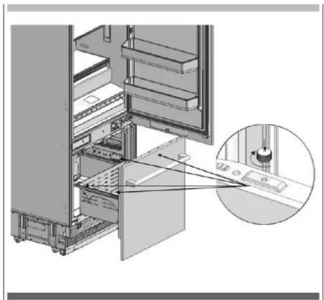
natural_image
Technical diagram of an internal server rack with a magnified inset showing a component detail (no text or symbols present)natural_image
Technical line drawing of a mechanical component with three parallel plates and downward arrows indicating assembly or alignment (no text or symbols)natural_image
Technical line drawing of a refrigerator with internal compartments and ventilation slots (no text or symbols)natural_image
Interior view of a refrigerator showing open doors and internal shelves, with a magnified inset highlighting the interior portion (no text or symbols visible)
WARNUNG
natural_image
Diagram of an open refrigerator showing internal shelves and door, with a magnified inset highlighting the interior structure (no text or symbols present)
ACHTUNG
natural_image
Technical line drawing of a door frame with three horizontal bars and vertical supports (no text or symbols)natural_image
Technical diagram of a door frame assembly with mounting bracket and control panel (no text or symbols)natural_image
Diagram of a device mounting bracket with arrows indicating assembly or adjustment (no text or symbols present)natural_image
Diagram showing a server rack with internal components and a magnified view of a vehicle on a conveyor belt (no text or symbols present)natural_image
Technical illustration of an open refrigerator with a magnified inset showing internal components (no text or symbols)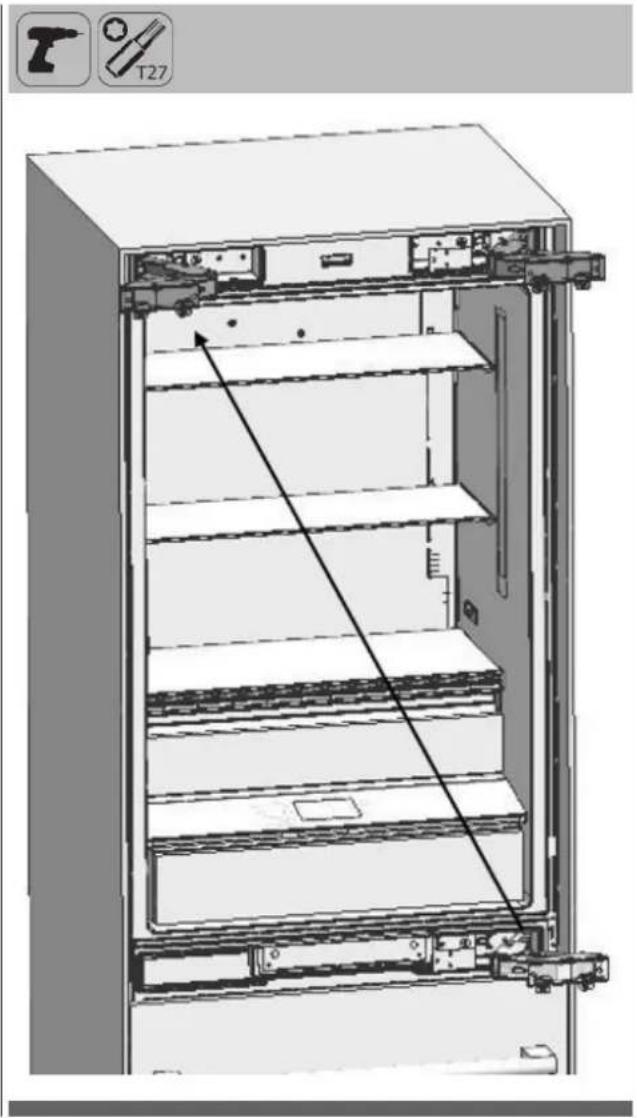
natural_image
Technical line drawing of an open refrigerator with visible door, shelves, and mounting brackets (no text or symbols)
natural_image
Technical illustration of an open refrigerator with a close-up inset showing internal components (no text or symbols)natural_image
Technical line drawing of a mechanical assembly with no visible text or symbolsTABLA DE CONTENIDOS PÁGINA


ADVERTENCIA
natural_image
3D line drawing of a two-door cabinet with doors open and one door closed, showing internal structure (no text or symbols)con panel 19 mm (3/4"):616mm (24 1/4)

FBCD 761 TNF EDBL FBCD 762 TNF EDBL
A 388mm (15 9/32")

natural_image
Technical line drawing of an open refrigerator with labeled door and side panel (no text or symbols)FBCD 761 TNF EDBL FBCD 762 TNF EDBL
A 824mm (32 7/16")
B 756mm (29 3/4")
C 1398mm (55 1/32")
FBCD 761 TNF EDBL FBCD 762 TNF EDBL
A 1127mm (443/8")
B 756mm (29 3/4")
C 371mm (14 5/8")
D 1338mm (52 11/16")

FBCD 761 TNF EDBL
FBCD 762 TNF EDBL

natural_image
Three black-and-white icons showing a push truck, a worker in hard hat, and an overalls (no text or symbols)natural_image
3D line drawing of a rectangular cabinet or shelf unit with three vertical panels and a horizontal panel, no text or symbols present.natural_image
Exploded view diagram of a server rack unit with internal components and mounting brackets (no text or labels)
ATENCIÓN
natural_image
Technical illustration of an internal storage or rack system with a magnified inset showing a component detail (no text or symbols present)natural_image
3D technical illustration of a mechanical device with internal components and mounting base (no visible text or symbols)natural_image
Technical illustration of a mechanical assembly with an inset close-up showing a tool interacting with a component (no text or symbols present)natural_image
Diagram of a refrigerator interior showing door, drawer, and shelf with an inset close-up of the tray (no text or symbols)natural_image
Technical line drawing of a mechanical assembly with mounting base and structural components (no text or symbols)natural_image
Technical line drawing of a mechanical assembly with mounting base and structural components (no text or symbols)
ADVERTENCIA
natural_image
Technical illustration of a mechanical assembly with a circular component and supporting frame (no text or symbols)
ATENCIÓN
natural_image
Technical illustration of a server rack with cable routing and a close-up inset showing internal components (no text or symbols)
natural_image
Two black-and-white icons: a pencil and a screwdriver, both without any text or symbols.
ADVERTENCIA
natural_image
Interior view of a refrigerated industrial machine with cooling unit and fan assembly (no visible text or symbols)natural_image
Technical line drawing of a cabinet with an inset showing internal components (no text or symbols)natural_image
Technical line drawing of an open refrigerator with internal compartments and a close-up inset showing the front panel (no text or symbols present)
natural_image
Interior view of a refrigerator showing open doors, shelves, and internal compartments with arrows indicating airflow or movement (no text or symbols present)natural_image
Line drawing of a refrigerator interior showing front and rear compartments with no text or symbolsnatural_image
Technical illustration of an industrial machine with two wrench icons and a close-up view of internal components (no text or symbols)natural_image
Technical line drawing of a mechanical assembly with no visible text or symbolsnatural_image
Technical illustration of a refrigerated appliance with ventilation grilles and a handle (no text or symbols)
natural_image
Technical line drawing of a refrigerator interior showing front and side views (no text or symbols)natural_image
Line drawing of a front view of a computer oven with labeled compartments and door (no text or symbols)
ADVERTENCIA
natural_image
Technical diagram showing a mechanical assembly with mounting bracket and adjustment elements (no text or symbols)natural_image
Technical illustration of an open refrigerator with internal compartments and mounting hardware (no text or symbols)natural_image
Technical illustration of a mechanical assembly with cutouts and mounting brackets (no text or symbols)natural_image
Pure technical diagram of a mechanical assembly with no text, numbers, or symbols
ADVERTENCIA
natural_image
Diagram showing a mechanical assembly with a bracket and force arrows, no text or symbols presentnatural_image
Simple 3D diagram of a rectangular plate with three small labeled items on its surface, no text or symbols present.natural_image
Pure technical diagram of a mechanical assembly with no text, numbers, or symbolsnatural_image
Diagram of a mechanical lever system with motion arrows indicating rotational motion (no text or symbols)
natural_image
Technical diagram of a mechanical assembly with two vertical supports and directional arrows indicating movement (no text or symbols present)natural_image
Simple line drawing of a triangular structure with an arrow indicating rotation, no text or symbols present.
natural_image
Technical line drawing of a multi-level refrigerator with top panel and front panel (no text or symbols)ES
natural_image
Technical diagram of a mechanical assembly with two views: top shows internal components, bottom shows close-up of a component (no text or symbols present)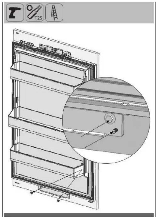
natural_image
Technical line drawing of a multi-panel refrigerator with an inset close-up showing internal components (no text or symbols)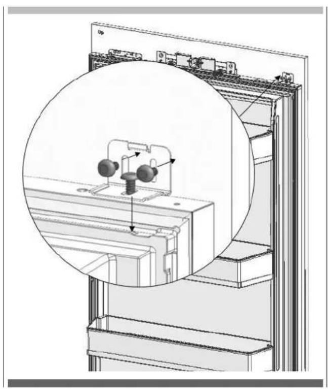
natural_image
Technical diagram of a mechanical assembly with a magnified inset showing internal components (no text or symbols)
natural_image
Technical diagram of a mechanical assembly with a circular inset view showing internal components (no text or labels)natural_image
Interior view of a refrigerator showing open doors and internal compartments, with an inset close-up highlighting the exterior panel (no text or symbols visible)natural_image
Interior view of a refrigerator showing open doors, shelves, and storage compartments (no text or labels)
ADVERTENCIA
natural_image
Diagram showing a mechanical assembly inside a room with an inset close-up of a tool interacting with a component (no text or symbols visible)natural_image
Technical diagram of a mechanical assembly with arrows indicating force or movement (no text or symbols present)natural_image
Interior view of a refrigerator with open door, showing internal compartments and storage racks (no text or symbols visible)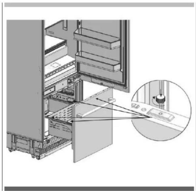
natural_image
Technical diagram of a server rack with an inset close-up showing internal components (no text or symbols)natural_image
Technical line drawing of a mechanical assembly with three horizontal bars and arrows indicating assembly direction (no text or symbols)natural_image
Technical diagram of a refrigerator with internal compartments and ventilation slots (no text or labels)natural_image
Interior view of a refrigerator showing open doors and internal shelves, with a magnified inset highlighting the interior portion (no text or symbols visible)
ADVERTENCIA
natural_image
Diagram of an open refrigerator showing internal shelves and door, with a magnified inset highlighting the interior structure (no text or symbols present)
ATENCIÓN
natural_image
Technical line drawing of a door frame with three horizontal bars and vertical supports (no text or symbols)natural_image
Technical diagram of a door frame assembly with mounting bracket and control panel (no text or symbols)natural_image
Diagram of a device mounting bracket with arrows indicating assembly or adjustment (no text or symbols present)natural_image
Diagram showing a mechanical assembly inside a server room, with an inset close-up of a device and a few circular arrows indicating motion (no text or symbols present)natural_image
Technical illustration of an open refrigerator with a magnified inset showing internal components (no text or symbols)natural_image
Technical line drawing of an open refrigerator with visible door, shelves, and internal components (no text or symbols)natural_image
Technical illustration of an open refrigerator with a close-up inset showing internal components (no text or symbols)natural_image
Technical line drawing of a structural frame with internal components and directional arrows (no text or symbols)ÍNDICE
PÁGINA
Local deinstalação


AVISO
natural_image
3D line drawing of a two-door cabinet with doors open and one door closed, showing internal structure (no text or symbols)Dimensão do produto
FBCD 761 TNF EDBL FBCD 762 TNF EDBL
A 756mm (29 3/4")
sem painel: 592mm (23 5/16")
com painel 19 mm (3/4"):616mm (24 1/4)

FBCD 761 TNF EDBL FBCD 762 TNF EDBL
A 388mm (15 9/32")
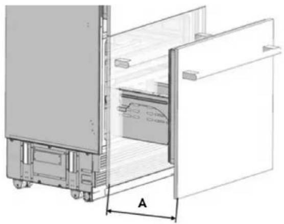
natural_image
Technical line drawing of an open refrigerator with labeled door and side panel (no text or symbols)FBCD 761 TNF EDBL FBCD 762 TNF EDBL
A 824mm (32 7/16")
B 756mm (29 3/4")
C 1398mm (55 1/32")
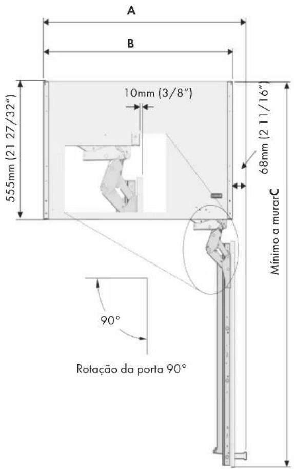
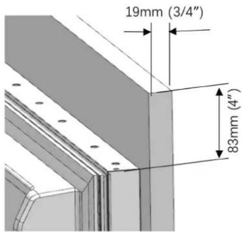
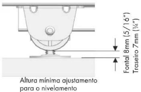
FBCD 761 TNF EDBL
FBCD 762 TNF EDBL
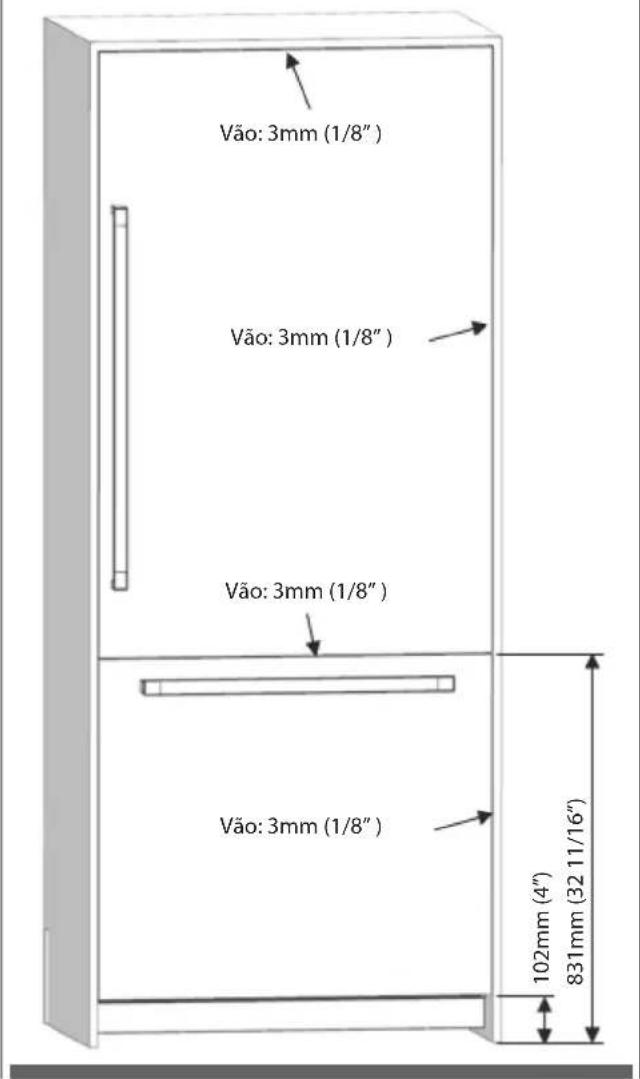
natural_image
Three black-and-white icons showing a push truck, a worker in hard hat, and an overalls (no text or symbols)natural_image
3D line drawing of a rectangular cabinet or enclosure with three vertical panels and a horizontal base, no text or symbols present.natural_image
Exploded view diagram of a server rack unit with internal components and mounting brackets (no text or labels)
ATENÇÃO
natural_image
Technical illustration of an internal storage or rack system with a magnified inset showing a component detail (no text or symbols present)- Remover a gaveta inferior.
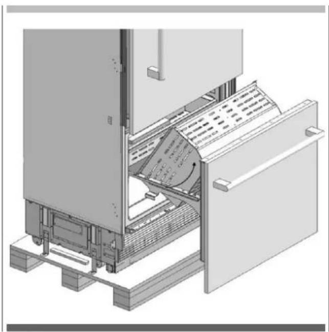
natural_image
3D technical illustration of a mechanical device with internal components and mounting base (no visible text or symbols)natural_image
Technical illustration of a mechanical assembly with an inset close-up showing a component detail (no text or symbols present)natural_image
3D diagram of a refrigerator interior showing door, drawer, and shelf with internal components and directional arrows (no text or symbols)natural_image
Technical line drawing of a mechanical assembly with mounting base and structural components (no text or symbols)natural_image
Technical diagram of a mechanical assembly with mounting base and structural components (no text or symbols)
AVISO
natural_image
Technical illustration of a mechanical assembly with a circular component and supporting base (no text or symbols)natural_image
Diagram showing a crane lifting a sheet metal frame next to a vertical industrial machine, with two identical human icons above (no text or symbols present)
ATENÇÃO
natural_image
Technical illustration of a server rack with zoomed-in views showing internal components (no text or symbols)
INFORMAÇÕES IMPORTANTES
natural_image
Two black-and-white icons: a stylized tool and a screwdriver, both without any text or symbols.
AVISO
natural_image
Technical line drawing of an internal appliance or enclosure with no visible text, numbers, or symbols.natural_image
Technical line drawing of a cabinet with an inset showing internal components (no text or symbols)natural_image
Technical illustration of an open refrigerator with internal compartments and a close-up inset showing the front panel (no text or symbols present)
INFORMAÇÕES IMPORTANTES
natural_image
Interior view of a refrigerator showing open doors, shelves, and internal compartments (no text or labels)Aparafusar o suporte superior
natural_image
Line drawing of a refrigerator interior showing front and rear compartments with no text or symbolsnatural_image
Technical illustration of an industrial machine with two wrench icons and a close-up view of internal components (no text or symbols)natural_image
Technical line drawing of a mechanical assembly with no visible text or symbolsnatural_image
Technical illustration of a refrigerated appliance with ventilation grilles and a handle (no text or symbols)
INFORMAÇÕES IMPORTANTES
natural_image
Technical line drawing of a refrigerator interior showing front and side views (no text or symbols)natural_image
Line drawing of a front view of a computer oven with control panel and door (no text or symbols)
AVISO
natural_image
Technical diagram showing a mechanical assembly with a tool and mounting bracket (no text or symbols)natural_image
Technical illustration of an open refrigerator with internal compartments and mounting hardware (no text or symbols)natural_image
Technical illustration of a mechanical assembly with cutouts and mounting brackets (no text or symbols)PT
• Fixar a maçaneta da porta FRZ.
natural_image
Pure technical diagram of a mechanical assembly with no text, numbers, or symbols
AVISO
natural_image
Diagram showing a mechanical assembly with a tool and a bracket, no text or symbols present- Fixar 3 suportes de chapa (Item N.14) usando 6 parafusos (Item N.15) à frente.
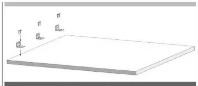
natural_image
Simple 3D diagram of a rectangular plate with three small L-shaped cutouts and a downward arrow, no text or symbols present.natural_image
Pure technical diagram of a mechanical assembly with no text, numbers, or symbolsnatural_image
Diagram of a mechanical lever system with motion arrows indicating rotational motion (no text or symbols)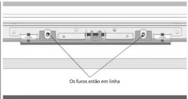
natural_image
Technical diagram of a mechanical assembly with two vertical supports and directional arrows indicating movement (no text or symbols present)natural_image
Simple line drawing of a triangular structure with an arrow indicating rotation, no text or symbols present.natural_image
Technical line drawing of a multi-level rack cabinet or storage unit with mounting brackets and ventilation slots (no text or symbols)PT
natural_image
Technical diagram of a mechanical assembly with two views: top shows a component inserted into a housing, bottom shows a close-up of a mechanical component (no text or symbols present)
natural_image
Technical line drawing of a multi-panel refrigerator with an inset close-up showing internal components (no text or symbols)
natural_image
Technical diagram of a mechanical assembly with a magnified inset showing internal components (no text or symbols)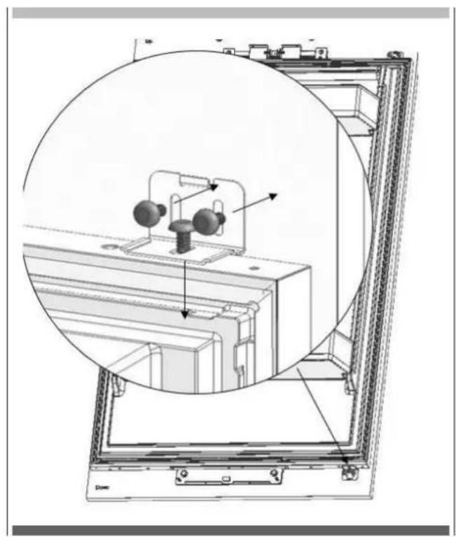
natural_image
Technical diagram of a mechanical assembly with a circular inset view showing internal components (no text or labels)natural_image
Interior view of a refrigerator showing open doors and internal compartments, with an inset close-up highlighting the exterior panel (no text or symbols visible)natural_image
Interior view of a refrigerator showing open doors, shelves, and storage compartments (no text or labels)
AVISO
natural_image
Diagram showing a mechanical assembly inside a room with an inset close-up of a tool interacting with a component (no text or symbols visible)natural_image
Technical diagram of a mechanical assembly with arrows indicating force or movement (no text or symbols present)natural_image
Interior view of a refrigerator with open door, showing internal compartments and storage racks (no text or symbols visible)
natural_image
Technical diagram of a server rack with an inset close-up showing internal components (no text or symbols)natural_image
Technical line drawing of a mechanical component with three horizontal bars and arrows indicating assembly or alignment (no text or symbols)• Fixar os selos de fecho laterais (2) (3).
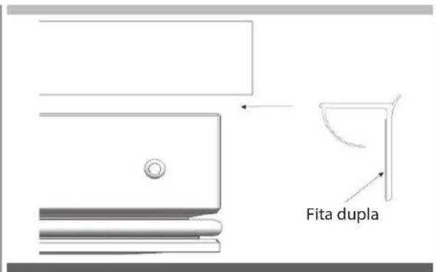
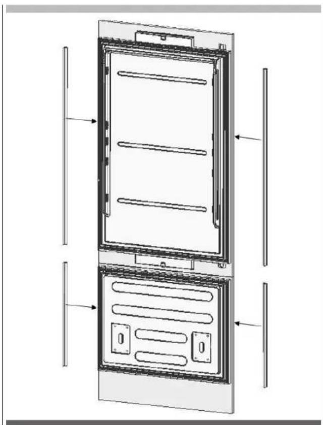
natural_image
Technical line drawing of a refrigerator internal frame with mounting brackets and ventilation slots (no text or symbols)PT AJUSTE DA DOBRADIÇA
natural_image
Interior view of a refrigerator showing open doors and internal shelves, with a magnified inset highlighting the interior portion (no text or symbols visible)
AVISO
natural_image
Technical illustration of an open refrigerator with a magnified inset showing internal components (no text or symbols)
ATENÇÃO
natural_image
Technical line drawing of a door frame with three horizontal bars and side supports (no text or symbols)natural_image
Technical diagram of a door frame assembly with mounting bracket and control panel (no text or symbols)natural_image
Diagram of a device panel assembly with mounting bracket and adjustment arrows (no text or symbols)natural_image
Diagram showing a server rack with internal components and a magnified view of a device inside (no text or symbols)natural_image
Technical illustration of an open refrigerator with a magnified inset showing internal components (no text or symbols)natural_image
Technical line drawing of an open refrigerator with visible internal compartments and mounting brackets (no text or symbols)
natural_image
Diagram of an open refrigerator with a close-up inset showing internal components (no text or labels)natural_image
Technical line drawing of a structural frame with internal components and directional arrows (no text or symbols)FULGOR
MILANO
SINCE 1949