EVLDGH - Extraction fan Air King - Free user manual and instructions
Find the device manual for free EVLDGH Air King in PDF.
User questions about EVLDGH Air King
0 question about this device. Answer the ones you know or ask your own.
Ask a new question about this device
Download the instructions for your Extraction fan in PDF format for free! Find your manual EVLDGH - Air King and take your electronic device back in hand. On this page are published all the documents necessary for the use of your device. EVLDGH by Air King.
USER MANUAL EVLDGH Air King
IMPORTANT INSTRUCTIONS - OPERATING MANUAL
EVLD Series

text_image
AirKing Ventilation Products®Exhaust Fan with Light

READ AND SAVE THESE INSTRUCTIONS
READ CAREFULLY BEFORE ATTEMPTING TO ASSEMBLE, INSTALL, OPERATE OR MAINTAIN THE PRODUCT DESCRIBED. PROTECT YOURSELF AND OTHERS BY OBSERVING ALL SAFETY INFORMATION. FAILURE TO COMPLY WITH INSTRUCTIONS COULD RESULT IN PERSONAL INJURY AND/OR PROPERTY DAMAGE!

RETAIN INSTRUCTIONS FOR FUTURE REFERENCE.
GENERAL SAFETY INFORMATION

When using electrical appliances, basic precautions should always be followed to reduce the risk of fire, electric shock and injury to person, including the following:


WARNING: TO REDUCE THE RISK OF FIRE, ELECTRIC SHOCK AND INJURY TO PERSON, OBSERVE THE FOLLOWING:
a) Use this unit only in the manner intended by the manufacturer. If you have questions, contact the manufacturer.
b) Before servicing or cleaning the unit, switch power off at service panel and lock the service disconnecting means to prevent power from being switched on accidentally. When the service disconnecting means cannot be locked, securely fasten a prominent warning device, such as a tag, to the service panel.

WARNING: TO REDUCE THE RISK OF FIRE, ELECTRIC SHOCK AND INJURY TO PERSON, OBSERVE THE FOLLOWING:
a) Installation work and electrical wiring must be done by qualified person(s) in accordance with all applicable codes and standards, including fire-related construction.
b) Sufficient air is needed for proper combustion and exhausting of gases through the flue (chimney) of fuel burning equipment to prevent back drafting. Follow the heating equipment manufacturer's guideline and safety standards such as those published by the National Fire Protection Association (NFPA) and the American Society for Heating, Refrigeration, and Air Conditioning Engineers (ASHRAE), and the local code authorities.
c) When cutting or drilling into wall or ceiling, do not damage electrical wiring and other hidden utilities.

CAUTION: FOR GENERAL VENTILATING USE ONLY. DO NOT USE TO EXHAUST HAZARDOUS OR EXPLOSIVE MATERIALS AND VAPORS.
d) Ducted fans must always be vented to the outdoors.
e) If this unit is to be installed over a tub or shower, it must be marked as appropriate for the application and be connected to a GFCI (Ground Fault Circuit Interrupter) – protected branch circuit.
f) Do not install in a ceiling with thermal insulation value greater than R40.
g) This unit must be grounded.
h) To avoid motor bearing damage and noisy and/or unbalanced impellers, keep drywall spray, construction dust, etc. off power unit.
i) Read all instructions before installing or using exhaust fan.
j) Suitable for use with electronic speed control device.

WARNING: DO NOT USE IN KITCHENS.

WARNING: THE DUCTING FROM THIS FAN TO THE OUTSIDE OF THE BUILDING HAS A STRONG EFFECT ON THE AIR FLOW, NOISE AND ENERGY USE OF THE FAN. USE THE SHORTEST, STRAIGHTEST DUCT ROUTING POSSIBLE FOR BEST PERFORMANCE, AND AVOID INSTALLING THE FAN WITH SMALLER DUCTS THAN RECOMMENDED. INSULATION AROUND THE DUCTS CAN REDUCE ENERGY LOSS AND INHIBIT MOLD GROWTH. FANS INSTALLED WITH EXISTING DUCTS MAY NOT ACHIEVE THEIR RATED AIRFLOW.
INSTALLATION INSTRUCTIONS
CAUTION: MAKE SURE POWER IS SWITCHED OFF AT SERVICE PANEL BEFORE STARTING INSTALLATION.
SECTION 1
Preparing the Exhaust Fan
- Unpack fan from the carton and confirm that all pieces are present. In addition to the exhaust fan you should have:
1 - Grill
1 - Damper Assembly (attached)
4 - Mounting Rails
1 - Mounting Flange
1 - LED Lamp
1 - Instruction/Safety Sheet
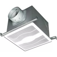
- Choose the location for your fan. To ensure the best air and sound performance, it is recommended that the length of ducting and the number of elbows be kept to a minimum, the radius of each elbow be as large as possible for the installation, and that insulated hard ducting be used. Larger duct sizes will reduce noise and airflow restrictions. This fan will require at least 10" of clearance in the ceiling or wall, and will mount through drywall up to 3/4" thick.
- No additional vibration deadening materials are needed for this fan.
SECTION 2
New Construction
NOTE: If the mounting flange is installed on the fan housing, remove the two screws that connect the ceiling mounting flange to the housing and set aside (Figure 17).
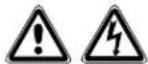
- Install the rails into the mounting channel on the housing. Center the mounting channel in the slots on the housing, then from inside the housing tighten the mounting channel nuts so the channel is securely in place. Position the housing next to the joist. Line up housing so that it will be flush with the finished ceiling. Secure the ends of the rails with screws or nails (not included) to the joists and slide the housing into the final position (Figure 1).
text_image
Housing Mounting Rails Joist Figure 1SECTION 3
Existing Construction
NOTE: If the mounting flange is installed on the fan housing, remove the two screws that connect the ceiling mounting flange to the housing and set aside (Figure 17).
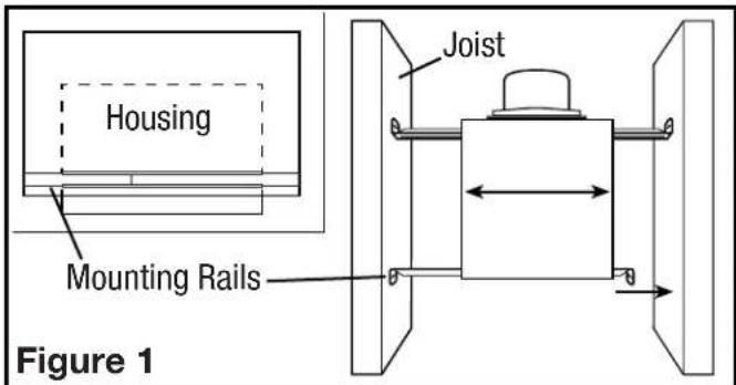
- Set housing in position between the joist and trace an outline onto the ceiling material (Figure 2). Set housing aside and cut opening, being careful not to cut or damage any electrical or other hidden utilities. Install the rails into the mounting channel on the housing. Center the mounting channel in the slots on the housing, then from inside the housing tighten the mounting channel nuts so the channel is securely in place. Position the housing in the previously cut hole so that it is flush with the finished ceiling. Secure the ends of the rails to the joists (Figure 1).
text_image
Joist Figure 2SECTION 4
Ducting
NOTE: 6" OR LARGER RIGID DUCT IS RECOMMENDED FOR BEST PERFORMANCE.

CAUTION: ALL DUCTING MUST COMPLY WITH LOCAL AND NATIONAL BUILDING CODES.
NOTE: The ducting from this fan to the outside of the building has a strong effect on the air flow, noise and energy use of the fan. Use the shortest, straightest duct routing possible for best performance, and avoid installing the fan with smaller ducts than recommended. Insulation around the ducts can reduce energy loss and inhibit mold growth. Fans installed with existing ducts may not achieve their rated air flow.
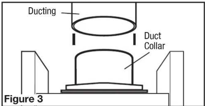
- Connect the ducting to the fan's duct collar (Figure 3). Secure in place using tape or screw clamp. Always duct the fan to the outside through a wall or roof cap. It is recommended that low restriction termination fittings be used.
text_image
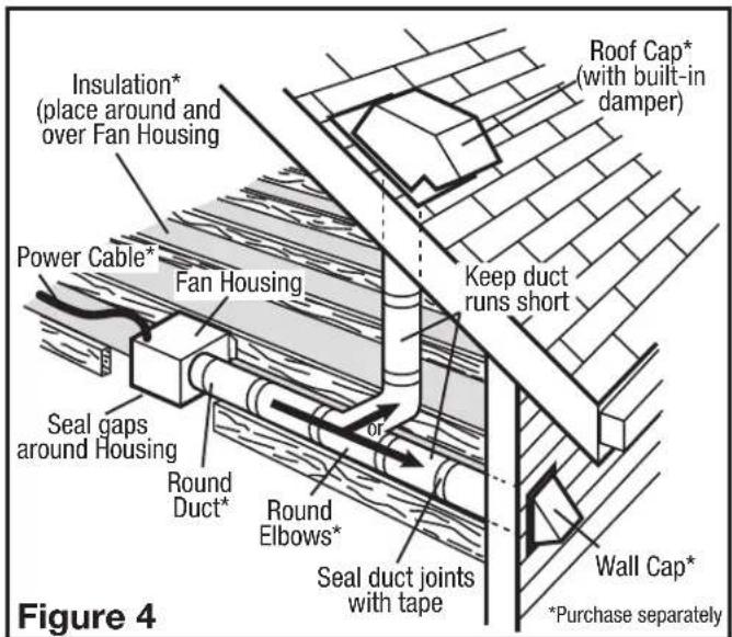
Ducting Duct Collar Figure 3- Ensure duct joints and exterior penetrations are sealed with caulk or other similar material to create an air-tight path to minimize building heat loss or gain and to reduce the potential for condensation. Place/wrap insulation around duct and/or fan to in order to minimize possible condensation buildup within the duct, as well as building heat loss or gain (Figure 4).
text_image
Insulation* (place around and over Fan Housing) Power Cable* Fan Housing Seal gaps around Housing Round Duct* Round Elbows* Seal duct joints with tape Roof Cap* (with built-in damper) Keep duct runs short Wall Cap* *Purchase separately Figure 4SECTION 5
Wiring


CAUTION: MAKE SURE POWER IS SWITCHED OFF AT SERVICE PANEL BEFORE STARTING INSTALLATION.

CAUTION: ALL ELECTRICAL CONNECTIONS MUST BE MADE IN ACCORDANCE WITH LOCAL CODES, ORDINANCES, OR NATIONAL CAL CODE. IF YOU ARE UNFAMILIAR WITH METHODS OF INSTALLING ELECTRICAL SECURE THE SERVICES OF A QUALIFIED ELECTRICIAN.
NOTE: This unit includes a side access panel for wiring that does not require the removal of the fan's blower assembly. If you choose to wire the unit from the inside, you will need to remove the blower assembly and internal wiring compartment. Both methods are equally effective.
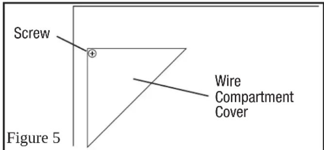
1a. External Wire Compartment: Remove the wire compartment cover screw and place cover in a secure place (Figure 5).
text_image
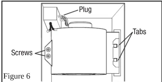
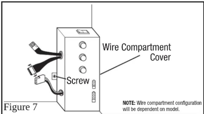
Screw Figure 5 Wire Compartment Cover1b. Internal Wire Compartment: If the motor is already installed in the housing, remove the two screws holding the blower assembly in place. Lift up on the assembly and slide it out of the tabs on the housing (Figure 6). Remove the wire compartment cover screw and place the cover in a secure place (Figure 7).
text_image
Plug Screws Tabs Figure 6NOTE: If the fan motor plug is connected to the fan housing receptacle, unplug so the blower assembly can be completely removed.
text_image
Wire Compartment Cover Screw Figure 7 NOTE: Wire compartment configuration will be dependent on model.Standard Models
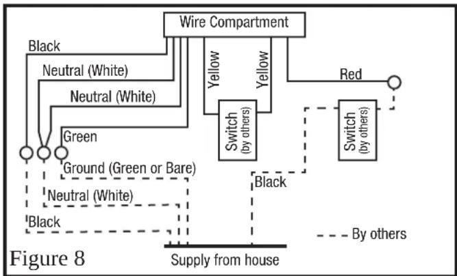
- Continuous Ventilation: Secure the electrical wires to the housing with an approved electrical connector. For two speed fans wired for continuous ventilation, connect the White wires of the fan to the White (Neutral) wire from the power source. Connect the ground wire from the house to the green wire from the fan housing. Connect the Black wire of the fan to the Black wire (Hot) from the power source. Using a properly grounded standard duplex toggle switch (such as Leviton 5224-2W, not included) connect the Black wire from the supply to one side of the top and bottom switch. Connect the Red wire (light) from the fan housing to the other side of the top switch. Using a second properly grounded standard duplex toggle switch, connect the Hot Yellow wire from the fan to the input of the switch. Connect the second Yellow wire from the fan to the output side of the switch. Closing the switch will change from normal to high speed (Figure 8).
flowchart
graph TD
    A["Wire Compartment"] --> B["Switch (by others)"]
    A --> C["Red"]
    B --> D["Switch (by others)"]
    B --> E["Green"]
    B --> F["Ground (Green or Bare)"]
    B --> G["Neutral (White)"]
    B --> H["Black"]
    C --> I["By others"]
    D --> J["Supply from house"]
    E --> J
    F --> J
    G --> J
    H --> J
NOTE: There may be more than one white fan wire that will need to be connected to the white wire from the supply.
NOTE: The yellow wire may contain a wire crimp nut which will have to be cut off and the wire stripped.
Motion Sensing Models
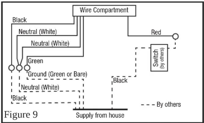
- Secure the electrical wires to the housing with an approved electrical connector. For two speed fans wired for continuous ventilation, connect the White wires of the fan to the White (Neutral) wire from the power source. Connect the ground wire from the house to the green wire from the fan housing. Connect the Black wire of the fan to the Black wire (Hot) from the power source. The fan will operate on low speed continuously and boost to high speed when motion is detected. Using a properly grounded standard duplex toggle switch (such as Leviton 5224-2W, not included) connect the black wire from the supply to one side of the top and bottom switch. Connect the red wire (light) from the fan housing to the other side of the top switch. A manual override switch (not included) can be used to provide a manual fan Off function (Figure 9).
flowchart
graph TD
    A["Wire Compartment"] --> B["Red"]
    A --> C["Switch (by others)"]
    C --> D["Supply from house"]
    A --> E["Black"]
    A --> F["Neutral (White)"]
    A --> G["Neutral (White)"]
    A --> H["Green"]
    A --> I["Ground (Green or Bare)"]
    A --> J["Neutral (White)"]
    A --> K["Black"]
    style A fill:#f9f,stroke:#333
    style C stroke-dasharray: 5 5
    style D stroke-dasharray: 5 5
    style E stroke-dasharray: 5 5
    style F stroke-dasharray: 5 5
    style G stroke-dasharray: 5 5
    style H stroke-dasharray: 5 5
    style I stroke-dasharray: 5 5
    style J stroke-dasharray: 5 5
    style K stroke-dasharray: 5 5
NOTE: There may be more than one white fan wire that will need to be connected to the white wire from the supply.
Humidity Sensing Models
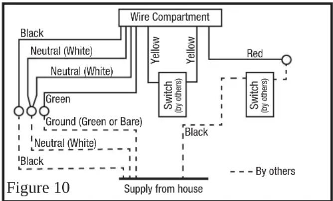
- Secure the electrical wires to the housing with an approved electrical connector. For two speed fans wired for continuous ventilation, connect the White wires of the fan to the White (Neutral) wire from the power source. Connect the ground wire from the house to the Green wire from the fan housing. Connect the Black wire of the fan to the Black wire (Hot) from the power source. The fan will operate on low speed continuously and boost to high upon a rise in humidity. Using a properly grounded switch, connect 1 yellow wire to each side of the switch. Closing the switch will change from normal to high speed. Using a properly grounded standard duplex toggle switch (such as Leviton 5224-2W, not included) connect the Black wire from the supply to one side of the top and bottom switch. Connect the Red wire (light) from the fan housing to the other side of the top switch. A manual override switch (not included) can be used to provide a manual fan Off function (Figure 10).
flowchart
graph TD
    A["Wire Compartment"] --> B["Switch (by others)"]
    A --> C["Red"]
    B --> D["Switch (by others)"]
    B --> E["Black"]
    C --> F["By others"]
    G["Ground (Green or Bare)"] --> H["Neutral (White)"]
    G --> I["Neutral (White)"]
    G --> J["Green"]
    K["Supply from house"] -.-> L["Black"]
    style A fill:#f9f,stroke:#333
    style B fill:#ccf,stroke:#333
    style C fill:#cfc,stroke:#333
    style D fill:#fcc,stroke:#333
    style E fill:#cff,stroke:#333
    style F fill:#ffc,stroke:#333
    style G fill:#fff,stroke:#333
    style H fill:#fff,stroke:#333
    style I fill:#fff,stroke:#333
    style J fill:#fff,stroke:#333
    style K fill:#fff,stroke:#333
NOTE: The yellow wire may contain a wire crimp nut which will have to be cut off and the wire stripped.
Humidity and Motion Sensing Models
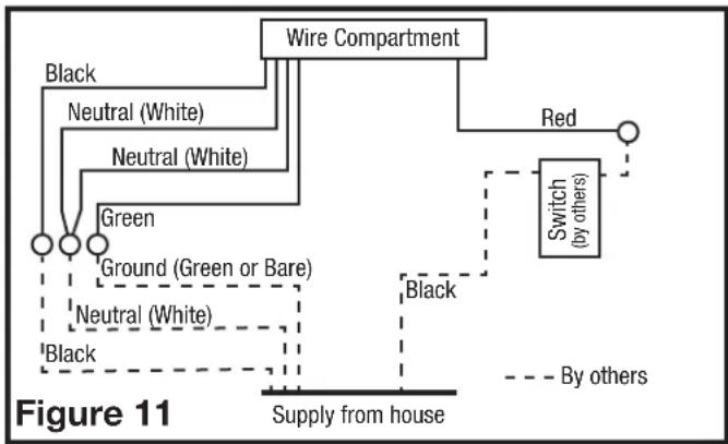
- Secure the electrical wires to the housing with an approved electrical connector. For two speed fans wired for continuous ventilation, connect the White wires of the fan to the White (Neutral) wire from the power source. Connect the ground wire from the house to the green wire from the fan housing. Connect the Black wire of the fan to the Black wire (Hot) from the power source. The fan will operate on low speed continuously and boost to high speed when motion is detected. Using a properly grounded standard duplex toggle switch (such as Leviton 5224-2W, not included) connect the black wire from the supply to one side of the top and bottom switch. Connect the red wire (light) from the fan housing to the other side of the top switch. A manual override switch (not included) can be used to provide a manual fan Off function (Figure 11).
flowchart
graph TD
    A["Wire Compartment"] --> B["Red"]
    A --> C["Switch (by others)"]
    A --> D["Ground (Green or Bare)"]
    A --> E["Neutral (White)"]
    A --> F["Black"]
    A --> G["Green"]
    H["Supply from house"] --> I["Black"]
    style A fill:#f9f,stroke:#333
    style B fill:#ccf,stroke:#333
    style C fill:#cfc,stroke:#333
    style D fill:#fcc,stroke:#333
    style E fill:#cff,stroke:#333
    style F fill:#ffc,stroke:#333
    style G fill:#cfc,stroke:#333
    style H fill:#fcc,stroke:#333
    style I fill:#fff,stroke:#333
- Carefully tuck wire back inside wire compartment and replace wire compartment cover securing with the screw that was removed earlier.
NOTE: The fan's receptacle wires might need to be pulled outside compartment for connection. Only pull the five loose wires outside of compartment. Additional wires will be present.
NOTE: Unit must be grounded according to all local and national codes.
SECTION 6
Completing the Installation
- Use a sealant appropriate for contact with the building materials present and for the temperature requirements of the installation to prevent air leakage from unconditioned spaces is recommended. If gaps between unit housing and ceiling are great, additional material (backing rod, ceiling material) may be required.
NOTE: This fan is rated for direct insulation contact (Type IC) and it is recommended that this fan be completely covered by insulation in order to reduce heat loss or gain to unconditioned space.
- If the fan's blower assembly was removed during the wiring process, reinstall the blower by reversing the directions in Section 5 (Wiring), Step 1b.
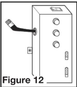
3a. STANDARD MODELS: Plug the fan's 2 pin and 3 pin quick connect motor cords into the corresponding receptacle located on the wire compartment cover. These cords will only fit one way into the receptacles (Figure 12).
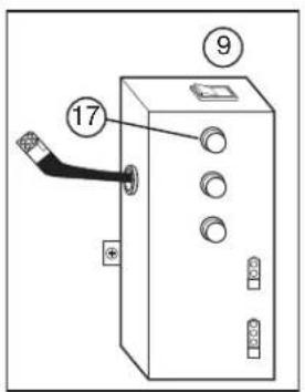
3b. MOTION SENSING MODELS: Plug the fan's 2 pin and 3 pin quick connect motor cords into the corresponding receptacle located on the wire compartment cover. These cords will only fit one way into the receptacles (Figure 13).
3c. HUMIDITY SENSING MODELS: Plug the fans 2 pin and 3 pin quick connect motor cords into the corresponding receptacle located on the wire compartment cover. Connect the two pin connector from the humidistat compartment to the two pin connector from the side of the wire compartment cover. These cords only fit one way into the receptacles (Figure 14).
natural_image
Diagram of an electrical cabinet with a cable and indicator lights, labeled Figure 12 (no text or symbols on the diagram itself)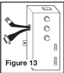
natural_image
Diagram of a device with two USB connectors and labeled components, no readable text or symbols present.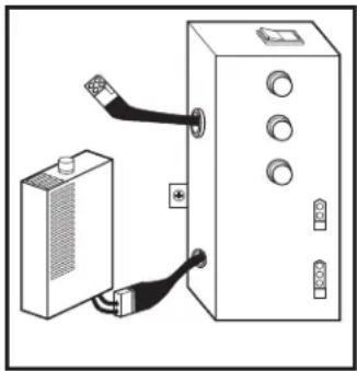
natural_image
Diagram showing a device connected to a control panel with cable (no text or symbols visible)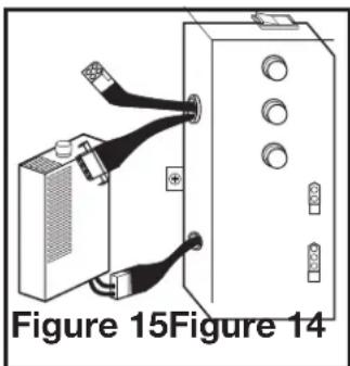
natural_image
Diagram of a device with two connectors and a box, labeled Figure 15 (no text or symbols on the diagram itself)3d. HUMIDITY SENSING MODELS: Plug the fans 2 pin and 3 pin quick connect motor cords into the corresponding receptacle located on the wire compartment cover. Connect the two pin connector from the humidistat compartment to the two pin connector from the side of the wire compartment cover. These cords only fit one way into the receptacles (Figure 15).
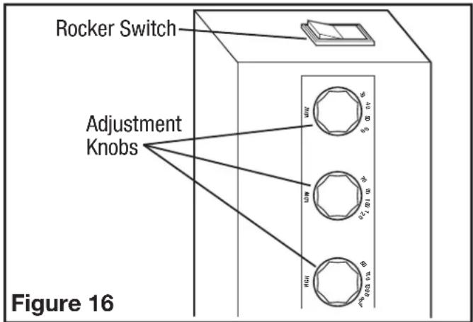
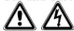
- VARIABLE SPEED: First decide if you will require more or less than 65 CFM of ventilation on the low speed setting. If it is less than 65 CFM place the Low CFM Range rocker switch on the 30-60 range. If it is more, place the low CFM range rocker switch on the 70-120 range. Once you have decided on the minimum required airflow, the fans low speed CFM level can be adjusted by using either the lower adjustment knob (30-60 CFM) or the middle adjustment knob (70-120 CFM). The desired high speed CFM can be adjusted by using the upper most adjustment knob (Figure 16).
text_image
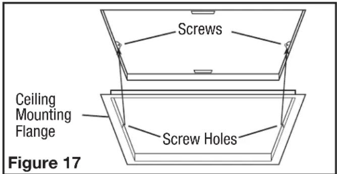
Rocker Switch Adjustment Knobs Figure 16- Install the ceiling mounting flange to cover any gaps which exist between the housing and the finished ceiling. Remove the two screws that connect the ceiling mounting flange to the housing. Put sealant (not provided) on inside edge of the ceiling mounting flange to ensure that the flange is sealed to the ceiling. Line up the screw holes in the ceiling mounting flange with the screw holes on the inside of the housing and press flange in place so it is tight against the ceiling. Reinstall ceiling flange mounting screws inside the housing (Figure 17).
text_image
Screws Ceiling Mounting Flange Screw Holes Figure 17NOTE: If the housing is mounted to far or not far enough into the ceiling for the flange to make a solid connection, loosen the mounting channel and adjust the housing up or down on the rails. Once in place, fully tighten the mounting channel nuts.
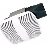
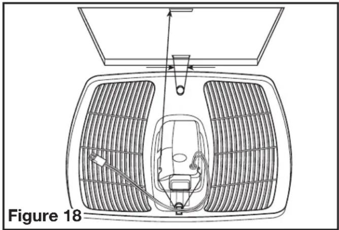
6a. STANDARD AND HUMIDITY SENSING MODELS: Install the grill by squeezing the springs together and installing it up into the slot furthest from the wire compartment on the fans housing. Attach the 4 pin quick connect from the grill to the 4 pin connector on the top of the wire cover. The cord will only fit one way into the receptacle. Install the other spring and push the grill up into position. (Figure 18).
natural_image
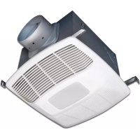
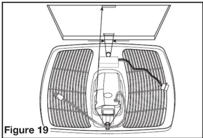
Diagram of a car interior with ventilation grilles and airflow indicators, labeled Figure 18 (no text or symbols on diagram itself)6b. MOTION SENSING MODELS: Install the grill by squeezing the springs together and installing it up into the slot furthest from the wire compartment on the fans housing. Attach the 4 pin quick connect from the grill to the 4 pin connector on the top of the wire cover. Attach the 4 pin quick connect from the motion sensor to the 4 pin connector on the top of the wire cover. The cords will only fit one way into the receptacle. Install the other spring and push the grill up into position. (Figure 19).
natural_image
Technical line drawing of a car interior with ventilation grilles and exhaust pipes (no text or symbols)- Open the light lens on the grill by pushing into the lens and allowing in to spring open. Install the 8.5 watt LED (included) into the lamp holder by lining up the pins on the lamp base to the socket of the lamp holder and turning the lamp body clockwise until the lamp snaps into place and is firmly seated in the lamp holder.
- Restore power and test your installation.
SECTION 7 Programming the Occupancy Sensor
1a. Setting the Occupancy Time Delay. This will set the amount of time the fan will continue to operate on high speed after the room is vacated. Locate the motion sensor on the fan's grill and press the button 2 times. The LED on the sensor will then flash the number of times to indicate the current setting, this will repeat 3 times:

natural_image
Simple line drawing of a circle above a vertical line, no text or symbols present1 time = 30 seconds 6 times = 12.5 minutes
2 times = 2.5 minutes 7 times = 15 minutes
3 times = 5 minutes 8 times = 17.5 minutes
4 times = 7.5 minutes 9 times = 20 minutes
5 times = 10 minutes*
1b. To adjust the setting, while the sensor is still flashing from Step 1a, press the button the number of times that corresponds with the amount of time you desire, for instance 3 times sets the delay to 5 minutes (see numbers in Step 1). The sensor will then flash the number of times for the new setting 3 times before exiting back to the programming mode.
2a Setting the Minimum On Time. This sets the minimum time the fan will operate on high speed once motion is detected within the room. This works in conjunction with the Occupancy Time Delay feature set in Steps 1a and 1b. For instance if you set the minimum time on for 15 minutes and the Time Delay for 5 minutes, the fan will operate for at least 15 minutes then 5 additional minutes.
NOTE: This is a minimum time that the fan will operate. If the room is occupied longer, the fan will continue to run until the room is vacated and the occupancy time delay has elapsed.
2b. Locate the motion sensor on the fan's grill and press the button 10 times. The LED on the sensor will then flash the number of times to indicate the current setting, this will repeat 3 times:
1 time = 0 minutes 4 times = 45 minutes
2 times = 15 minutes* 5 times = 60 minutes
3 times = 30 minutes
2c. To adjust the setting, while the sensor is still flashing from Step 2b, press the button the number of times that corresponds with the amount of time you desire, for instance 3 times sets the minimum on time to 30 minutes (see numbers in Step 2b). The sensor will then flash the number of times for the new setting 3 times before exiting back to the programming mode.
- Once all setting have been made and the sensor will return to detection mode and the LED will flash when occupancy of the room is detected.
SECTION 8 Setting the Humidistat
This fan may be equipped with a humidity sensor that automatically turns the fan on (or to high speed on dual speed models) when humidity is above set point and off (or back to low speed on dual speed models) when humidity is at or below set point. If the fan is operating too long or not enough, first check to see the humidity sensor set point. In cases where the ambient humidity level of the room rises higher than the preset level, the fan will turn on even if the room is not occupied. This helps prevent conditions that lead to mold growth.


CAUTION: MAKE SURE POWER IS SWITCHED OFF AT SERVICE PANEL BEFORE SERVICING THE UNIT.
- To set the desired humidity level of the room, remove the grill and locate the dehumidistat dial located on the wire compartment cover.
- Set the dial to the relative humidity you want the fan to maintain usually between 50 & 80%. Moist climates will require higher settings than dry climates. When the humidity level of the room is below this setting the fan will remain off (or low speed on dual speed models). When the humidity level rises above this setting the fan will turn on (or to high speed on dual speed models) and run until the humidity level falls below this setting.
- Reinstall the grill and restore power.
SECTION 10
Use and Care
CAUTION: MAKE SURE POWER IS SWITCHED OFF AT SERVICE PANEL BEFORE SERVICING THE UNIT.
- Cleaning the Grill: Remove grill and use a mild detergent, such as dishwashing liquid, and dry with a soft cloth. NEVER USE ANY ABRASIVE PADS OR SCOURING POWDERS. Completely dry grill before reinstalling. Refer to instructions in Section 6 Finishing the Installation, to reinstall grill.
- Cleaning the Fan Assembly: Wipe all parts with a dry cloth or gently vacuum the fan. NEVER IMMERSE ELECTRICAL PARTS IN WATER.

CAUTION: ALLOW BULBS TO COOL BEFORE REPLACING.
- Changing the Lamp: Disconnect power to the unit. Open the light lens on the grill by pushing into the lens and allowing in to spring open.
LED Bulb: Remove lamp by gently twisting the lamp base counterclockwise while applying outward pressure. Installation is the reverse of removal. Replace with a compatible GU24 8.5 watt LED lamp.
Troubleshooting Guide
| Trouble Probable Cause Suggested Remedy | ||
| 1. Fan does not operate when the switch is on. | 1a. A fuse may be blown or a circuit tripped.1b. Connector plug from motor is not plugged in.1c. Wiring is not connected properly.1d Motor has stopped operating. | 1a. Replace fuse or reset circuit breaker.1b. Turn off power to unit. Remove Grill and plug motor into receptacle in housing. Restore power to unit.1c. Turn off power to unit. Check that all wires are connected.1d. Replace motor. |
| 2. Fan is operating, but air moves slower than normal. | 2. Obstruction in the exhaust ducting. | 2. Check for any obstructions in the ducting. The most common are bird nests in the roof cap or wall cap where the fan exhausts to the outside. |
| 3. Fan is operating louder than normal | 3a. Motor is loose.3b. Fan blade is hitting housing of unit. | 3a. Turn off power to unit. Remove grill and check that all screws are fully tightened. Restore power to unit.3b. Call your dealer for service. |
LIMITED WARRANTY
WHAT THIS WARRANTY COVERS: This product is warranted against defects in workmanship and/or materials.
HOW LONG THIS WARRANTY LASTS: This warranty extends only to the original purchaser of the product and lasts for five (5) years from the date of original purchase or until the original purchaser of the product sells or transfers the product, whichever first occurs.
WHAT AIR KING WILL DO: During the warranty period, Air King will, at its sole option, repair or replace any part or parts that prove to be defective or replace the whole product with the same or comparable model.
WHAT THIS WARRANTY DOES NOT COVER: This warranty does not apply if the product was damaged or failed because of accident, improper handling, installation, or operation, shipping damage, abuse, misuse, unauthorized repairs made or attempted. This warranty does not cover shipping costs for the return of products to Air King for repair or replacement. Air King will pay return shipping charges from Air King following warranty repairs or replacement.
ANY AND ALL WARRANTIES, EXPRESSED OR IMPLIED (INCLUDING, WITHOUT LIMITATION, ANY IMPLIED WARRANTY OF MERCHANTABILITY), LAST FIVE YEARS FROM THE DATE OF ORIGINAL PURCHASE OR UNTIL THE ORIGINAL PURCHASER OF THE PRODUCT SELLS OR TRANSFERS THE PRODUCT, WHICHEVER FIRST OCCURS AND IN NO EVENT SHALL AIR KING'S LIABILITY UNDER ANY EXPRESS OR IMPLIED WARRANTY INCLUDE (I) INCIDENTAL OR CONSEQUENTIAL DAMAGES FROM ANY CAUSE WHATSOEVER, OR (II) REPLACEMENT OR REPAIR OF ANY HOUSE FUSES, CIRCUIT BREAKERS OR RECEPTACLES. NOTWITHSTANDING ANYTHING TO THE CONTRARY, IN NO EVENT SHALL AIR KING'S LIABILITY UNDER ANY EXPRESS OR IMPLIED WARRANTY EXCEED THE PURCHASE PRICE OF THE PRODUCT AND ANY SUCH LIABILITY SHALL TERMINATE UPON THE EXPIRATION OF THE WARRANTY PERIOD.
Some states and provinces do not allow limitations on how long an implied warranty lasts, or the exclusion or limitation of incidental or consequential damages, so these exclusions or limitations may not apply to you. This warranty gives you specific legal rights. You may also have other rights which vary from state to state and province to province. Proof of purchase is required before a warranty claim will be accepted.
CUSTOMER SERVICE:
Toll-Free (800) 465-7300
Our Customer Service team is available to assist you with product questions, service center locations, and replacement parts. They can be reached Monday through Friday, 8am-4pm Eastern. Please have your model number available, as well as the type and style (located on the label inside of your product).
Please do not return product to place of purchase.
www.airkinglimited.com
PARTS FOR DISCONTINUED, OBSOLETE AND CERTAIN OTHER PRODUCTS MAY NOT BE AVAILABLE. DUE TO SAFETY REASONS, MANY ELECTRONIC COMPONENTS AND MOST HEATER COMPONENTS ARE NOT AVAILABLE TO CONSUMERS FOR INSTALLATION OR REPLACEMENT.
Installer:
Place of Purchase:
Installation Date:
Model Number:
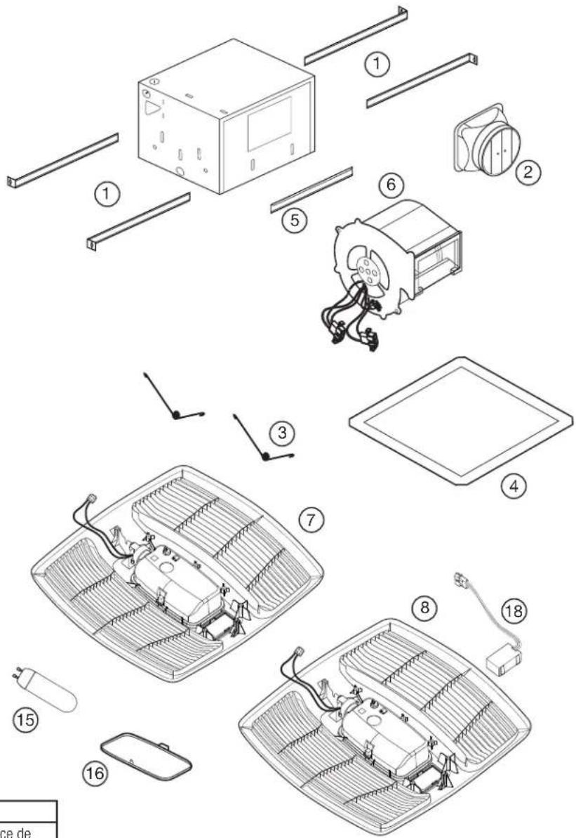
REPLACEMENT PARTS DIAGRAM
text_image
Diagram of an electrical cabinet with labeled components and numbered parts
text_image
10 17 200
text_image
Diagram showing electrical connections between a battery and an electrical cabinet with numbered components
text_image
Diagram showing connected components of an electrical device with numbered parts labeled 12, 13, and 14
text_image
Exploded view diagram of a smart air conditioner system with numbered components for identification| All Models | ||
| # Qty. Description Replacement Part # | ||
| 1 4 Mounting Rails 5S1299002 | ||
| 2 1 6" Metal Collar Assembly 5S5299100 | ||
| 3 2 Grill Springs 5S1202046 | ||
| 4 1 Ceiling Flange 5S1202050 | ||
| 5 2 Mounting Channel 5S1202123 | ||
| 6 1 Blower Assembly 5S1239125 | ||
| 15 1 8.5 Watt LED | 5S1299725 | |
| 16 1 Light Lens | 5S1239116 | |
| 17 3 Adjustment Knob | 5S1299802 | |
| Specific to Model EVLD | ||
| # Qty. Description Replacement Part # | ||
| 7 1 Grill Assembly 5S1250121 | ||
| 9 1 Wire Compartment Assembly | 5S1250126 | |
| Specific to Model EVLDG | ||
| # Qty. Description Replacement Part # | ||
| 8 1 Grill Assembly 5S1250120 | ||
| 10 1 Wire Compartment Assembly | 5S1250125 | |
| 18 1 Motion Sensor | 5S1999100 | |
| Specific to Model EVLDH | |||
| # Q | Qty. Description Replacement Part # | ||
| 7 1 | Grill Assembly 5S1250121 | ||
| 11 1 | Wire Compartment Assembly | 5S1250124 | |
| 13 1 | Knob | 5S1299802 | |
| 14 1 | Humidity Sensor Compartment | 5S1239826 | |
| Specific to Model EVLDGH | |||
| # Q | Qty. Description Replacement Part # | ||
| 8 1 | Grill Assembly 5S1250120 | ||
| 12 1 | Wire Compartment Assembly | 5S1250123 | |
| 13 1 | Knob | 5S1299802 | |
| 14 1 | Humidity Sensor Compartment | 5S1239826 | |
| 18 1 | Motion Sensor | 5S1999100 | |
NOTES:
INSTRUCTIONS IMPORTANTES - MODE D'EMPLOI
Série EVLD

text_image
AirKing Ventilation Products®text_image
Solve Figure 2SECTION 4
Conduits
NOTE: UN CONDUIT PLUS RIGIDE DE 6 PO OU PLUS EST RECOMMANDE POUR UNE MEILLEURE PERFORMANCE.

ATTENTION : TOUS LES CONDUITS DOIVENT ÊTRE CONFORMES AUX CODES DU BÂTIMENT LOCAUX ET NATIONAUX.
text_image
Raccord Vis Onglets Figure 6natural_image
Diagram of a device with a black cable inserted into a box, labeled Figure 12 (no text or symbols on the diagram itself)
natural_image
Diagram of a device with two USB connectors and labeled ports, no text or symbols presentnatural_image
Diagram showing a device connected to a control panel with cable (no text or symbols visible)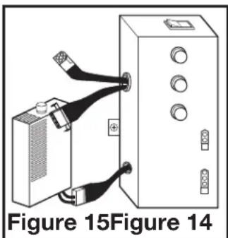
natural_image
Diagram of a device with two connectors and a box, labeled Figure 15 (no text or symbols on the diagram itself)natural_image
Technical line drawing of a vehicle interior with ventilation grilles and a central seat (no text or symbols)natural_image
Technical diagram of a vehicle interior with ventilation grilles and exhaust system (no text or symbols)natural_image
Simple diagram showing a circle above a smaller circle, with no text or symbols present.text_image
Diagram of an electrical cabinet with labeled components and numbered parts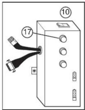
text_image
10 17 250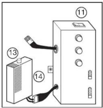
text_image
Diagram showing electrical connections between a battery and an enclosure with numbered labels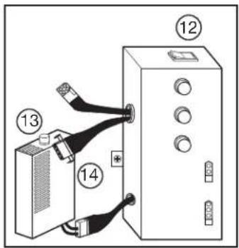
text_image
Diagram showing connected components of an electrical device with numbered parts labeled 12, 13, and 14