
BFQ70W - Extraction fan Air King - Free user manual and instructions
Find the device manual for free BFQ70W Air King in PDF.
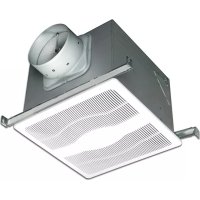
| Product Type | Exhaust Fan |
| Brand | Air King |
| Model | BFQ70W |
| Power Supply | 120 V, 60 Hz, AC |
| Main Functions | Exhaust air to outside; 4-inch round duct; built-in backdraft damper; ceiling or wall installation; suitable for new and existing construction |
| Maintenance and Cleaning | Removable grille; clean with mild detergent and soft cloth; vacuum for internal assembly; do not immerse electrical parts |
| Safety | Disconnect power before maintenance; grounding required; do not use with electronic speed control; do not install in a kitchen; requires GFCI circuit breaker in bathrooms |
| Spare Parts | Motor, grille, bracket, damper, fan wheel, etc. (see list in manual) |
| Repairability | Repairable with available spare parts; contact customer service |
| Warranty | 5 years limited |
| Customer Service | Toll-free 800-465-7300, website www.airkinglimited.com |
Frequently Asked Questions - BFQ70W Air King
User questions about BFQ70W Air King
0 question about this device. Answer the ones you know or ask your own.
Ask a new question about this device
Download the instructions for your Extraction fan in PDF format for free! Find your manual BFQ70W - Air King and take your electronic device back in hand. On this page are published all the documents necessary for the use of your device. BFQ70W by Air King.
USER MANUAL BFQ70W Air King
IMPORTANT INSTRUCTIONS - OPERATING MANUAL
BFQ, BFQW Series

Exhaust Fan

READ AND SAVE THESE INSTRUCTIONS
READ CAREFULLY BEFORE ATTEMPTING TO ASSEMBLE, INSTALL, OPERATE OR MAINTAIN THE PRODUCT DESCRIBED. PROTECT YOURSELF AND OTHERS BY OBSERVING ALL SAFETY INFORMATION. FAILURE TO COMPLY WITH INSTRUCTIONS COULD RESULT IN PERSONAL INJURY AND/OR PROPERTY DAMAGE!

RETAIN INSTRUCTIONS FOR FUTURE REFERENCE.
GENERAL SAFETY INFORMATION
When using electrical appliances, basic precautions should always be followed to reduce the risk of fire, electric shock and injury to person, including the following:
WARNING: TO REDUCE THE RISK OF FIRE, ELECTRIC SHOCK AND INJURY TO PERSON, OBSERVE THE FOLLOWING:
a) Use this unit only in the manner intended by the manufacturer. If you have questions, contact the manufacturer.
b) Before servicing or cleaning the unit, switch power off at service panel and lock the service disconnecting means to prevent power from being switched on accidentally. When the service disconnecting means cannot be locked, securely fasten a prominent warning device, such as a tag, to the service panel.
WARNING: TO REDUCE THE RISK OF FIRE, ELECTRIC SHOCK AND INJURY TO PERSON, OBSERVE THE FOLLOWING:
a) Installation work and electrical wiring must be done by qualified person(s) in accordance with all applicable codes and standards, including fire-related construction.
b) Sufficient air is needed for proper combustion and exhausting of gases through the flue (chimney) of fuel burning equipment to prevent back drafting. Follow the heating equipment manufacturer's guideline and safety standards such as those published by the National Fire Protection Association (NFPA) and the American Society for Heating, Refrigeration, and Air Conditioning Engineers (ASHRAE), and the local code authorities.
c) When cutting or drilling into wall or ceiling, do not damage electrical wiring and other hidden utilities.
CAUTION: FOR GENERAL VENTILATING USE ONLY. DO NOT USE TO EXHAUST HAZARDOUS OR EXPLOSIVE MATERIALS AND VAPORS.
d) Ducted fans must always be vented to the outdoors.
e) This unit must be grounded.
f) To avoid motor bearing damage and noisy and/or unbalanced impellers, keep drywall spray, construction dust, etc. off power unit.
g) Read all instructions before installing or using exhaust fan.
WARNING: TO REDUCE THE RISK OF FIRE, ELECTRIC SHOCK, DO NOT USE THIS FAN WITH ANY SOLID-STATE SPEED CONTROL DEVICE.
a) If this unit is to be installed over a tub or shower, it must be marked as appropriate for the application and be connected to a GFCI (Ground Fault Circuit Interrupter) – protected branch circuit.
b) Do not install wall mounted fans inside the shower area.

WARNING: DO NOT USE IN KITCHENS.

WARNING: THE DUCTING FROM THIS FAN TO THE OUTSIDE OF THE BUILDING HAS A STRONG EFFECT
ON THE AIR FLOW, NOISE AND ENERGY USE OF THE FAN. USE THE SHORTEST, STRAIGHTEST DUCT ROUTING POSSIBLE FOR BEST PERFORMANCE, AND AVOID INSTALLING THE FAN WITH SMALLER DUCTS THAN RECOMMENDED. INSULATION AROUND THE DUCTS CAN REDUCE ENERGY LOSS AND INHIBIT MOLD GROWTH. FANS INSTALLED WITH EXISTING DUCTS MAY NOT ACHIEVE THEIR RATED AIRFLOW.
SAVE THESE INSTRUCTIONS
INSTALLATION INSTRUCTIONS
CAUTION: MAKE SURE POWER IS SWITCHED OFF AT SERVICE PANEL BEFORE STARTING INSTALLATION.
SECTION 1
Preparing the Exhaust Fan
- Unpack fan from the carton and confirm that all pieces are present. In addition to the exhaust fan you should have:
1 - Grill 1 - Hardware Bag
1 - Damper Assembly (attached) 1 - Electrical Connector
1 - Mounting Bracket 3 - Wire Nuts
1 - Instruction/Safety Sheet
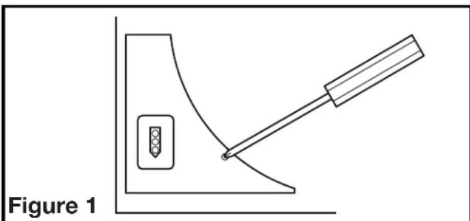
- Remove the wire compartment cover and store in the carton until needed so it does not get damaged or lost (Figure 1).
natural_image
Simple line drawing of a lever mechanism with a weight and handle, labeled Figure 1 (no text or symbols on the diagram itself)- Choose the location for your fan. To ensure the best air and sound performance, it is recommended that the length of ducting and the number of elbows be kept to a minimum, the radius of each elbow be as large as possible for the installation, and that insulated hard ducting be used. Larger duct sizes will reduce noise and airflow restrictions.
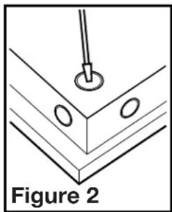
- Select the most convenient electrical knockout and remove using a straight-blade screw driver (Figure 2).
- No additional vibration deadening materials are needed for this fan.
natural_image
Diagram of a mechanical assembly with a pin and oval features, labeled Figure 2 (no text or symbols on the diagram itself)SECTION 2
New Construction - BFQ Models
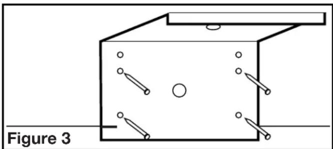
- Using the gauge on the mounting bracket, line up the bracket on the joist so the bottom of the fan will be flush with the finished ceiling. Nail or screw the bracket in place securely (Figure 3).
natural_image
Diagram of a 3D rectangular box with internal components and circular elements, labeled Figure 3 (no text or symbols on the diagram itself)
WARNING: PROPER INSTALLATION REQUIRES A MINIMUM OF 4 SCREWS LOCATED IN HOLES CLOSEST TO DRYWALL.
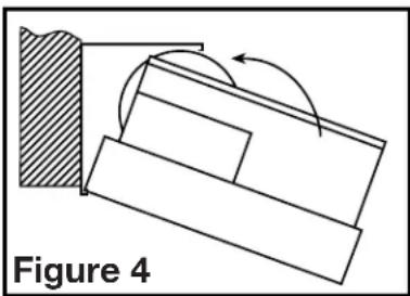
- Snap the fan body into the bracket (Figure 4). The fan can be snapped into position with the duct collar facing to the left or the right depending which is most convenient.
natural_image
Diagram showing a mechanical or structural component with an arrow indicating rotation, labeled 'Figure 4' (no text or symbols on the diagram itself)New Construction - BFQW Models (Oval Duct)
- Using the gauge on the bracket, line up the bracket on the side of a wall stud such that the bottom of the fan will be flush with the finished wall. The bracket should sit one drywall thickness forward on the stud (Figure 5).
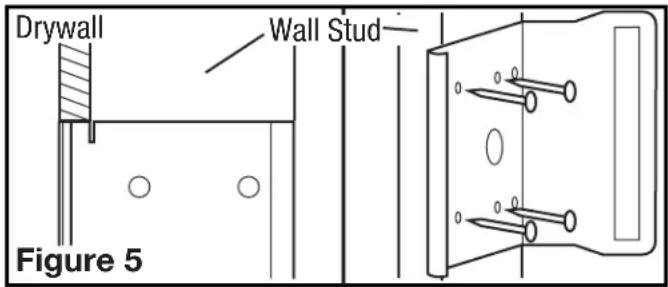
NOTE: For proper damper operation, the duct adaptor must be facing up towards the ceiling.
NOTE: 12 " minimum thickness drywall must be used for wall mount applications.
- Nail or screw the bracket in place securely.
- Snap the fan body into the bracket, making sure the duct collar is pointing upwards towards the ceiling (Figure 6).

natural_image
Technical line drawing of a mechanical component with no visible text or symbolsSECTION 3
Existing Construction - BFQ Models
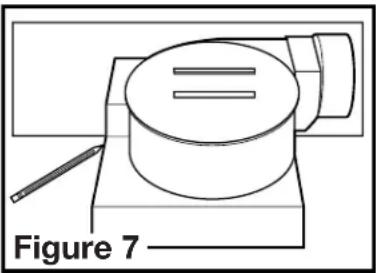
- Position housing against the joist or stud and trace an outline of the housing onto the ceiling/wall material. Set housing aside and cut opening, being careful not to cut or damage any electrical or other hidden utilities (Figure 7).
- Line up the bracket on the joist so the bottom of the fan will be flush with the finished ceiling. Nail or screw the snap-in bracket in place securely (Figure 3).
- Snap the fan body into the bracket (Figure 4). The fan can be snapped into position with the duct collar facing to the left or the right depending which is most convenient.
natural_image
Diagram of a cylindrical object mounted on a base with a pencil, labeled 'Figure 7' (no text or symbols on the object itself)Existing Construction - BFQW Models (Oval Duct)
- Remove a section of the wall material large enough for you to fit the fan housing into as well as gain access to the top plate, and have enough space to connect the ducting. This will typically be across two studs and approximately 24" starting at the top of the wall.
- Follow the instructions in Section 2 - New Constructions - BFQW Models (Oval Duct) to complete the installation.
NOTE: Wall installation into existing construction will require you to patch the wall material around the unit.
SECTION 4
Ducting
NOTE: 4" OR LARGER RIGID DUCT IS RECOMMENDED FOR BEST PERFORMANCE.

CAUTION: ALL DUCTING MUST COMPLY WITH LOCAL AND NATIONAL BUILDING CODES.
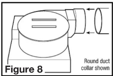
- Connect the ducting to the fan's duct collar (Figure 8). Secure in place using tape or screw clamp. Always duct the fan to the outside through a wall or roof cap. It is recommended that low restriction termination fittings be used.
NOTE: For oval duct connection, squeeze standard 4" round rigid ducting to form an oval shape then follow instructions in Step 1.
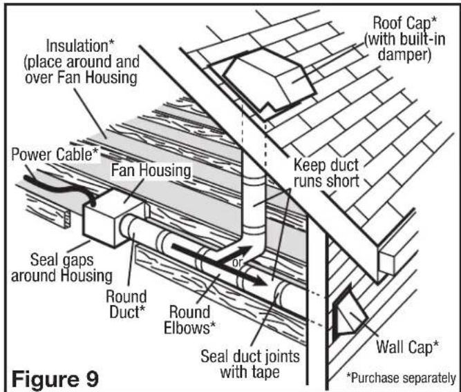
- Ensure duct joints and exterior penetrations are sealed with caulk or other similar material to create an air-tight path to minimize building heat loss or gain and to reduce the potential for condensation. Place/wrap insulation around duct and/or fan to in order to minimize possible condensation buildup within the duct, as well as building heat loss or gain (Figure 9).
SECTION 5
Wiring
CAUTION: MAKE SURE POWER IS SWITCHED OFF AT SERVICE PANEL BEFORE STARTING INSTALLATION.
CAUTION: ALL ELECTRICAL CONNECTIONS MUST BE MADE IN ACCORDANCE WITH LOCAL CODES, ORDINANCES, ORICAL CODE. IF YOU ARE UNFAMILIAR WITH METHODS OF INSTALLING G, SECURE THE SERVICES OF A QUALIFIED ELECTRICIAN.
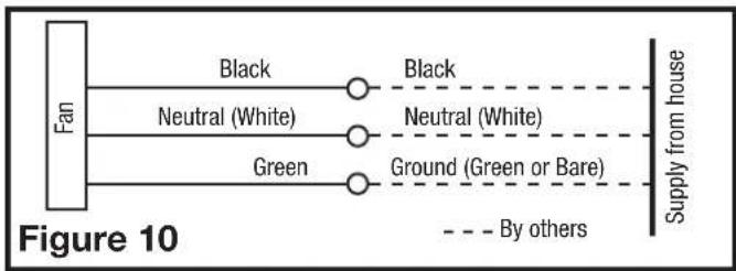
- Run wiring from an approved wall switch carrying the appropriate rating. One neutral (white), one ground (green or bare copper), and one hot (black lead connected to the switch). Secure the electrical wires to the housing with an approved electrical connector. Make sure you leave enough wiring in the box to make the connection to the fan's receptacle.
- From where you have access to inside the fan's junction box, connect the White wire from the house to the White wire from the fan's receptacle. Connect the Black wire from the wall switch to the Black wire from the fan's receptacle. Connect the ground wire from the house to the Green wire from the fan's receptacle (Figure 10). Use approved methods for all connections.
flowchart
graph LR
    A["Fan"] --> B["Black"]
    A --> C["Neutral (White)"]
    A --> D["Green"]
    B --> E["Black"]
    C --> F["Neutral (White)"]
    D --> G["Ground (Green or Bare)"]
    E -.-> H["Supply from house"]
    F -.-> H
    G -.-> H
    style A fill:#f9f,stroke:#333
    style H fill:#ccf,stroke:#333
SECTION 6
Completing the Installation
- Use a sealant appropriate for contact with the building materials present and for the temperature requirements of the installation to prevent air leakage from unconditioned spaces is recommended. If gaps between unit housing and ceiling are great, additional material (backing rod, ceiling material) may be required.
NOTE: This fan is rated for direct insulation contact (Type IC) and it is recommended that this fan be completely covered by insulation in order to reduce heat loss or gain to unconditioned space. - Reinstall the fan's wire compartment cover. Rotate the blower wheel by hand to ensure it spins freely. Plug the fan's quick connect motor cord into the receptacle. This cord will only fit one way into the receptacle (Figure 11).

NOTE: If using this fan to meet ASHRAE 62.2 requirements, locate the label inside the fan housing and fill in the appropriate information.
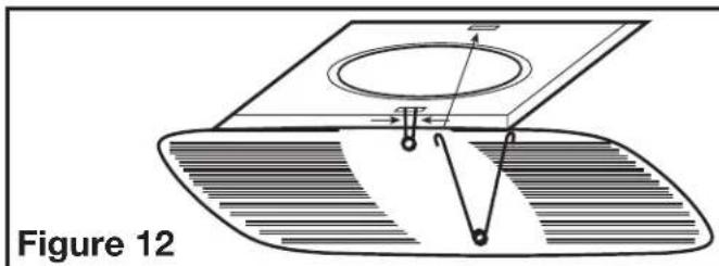
3. Install the grill by squeezing the two ends of the springs together and installing them up into the slots of the fan's housing. Push the grill up into position (Figure 12).
natural_image
Technical diagram of a mechanical assembly with labeled components and cross-section line (no readable text or symbols)- Restore power and test your installation.
SECTION 7
Use and Care


CAUTION: MAKE SURE POWER IS SWITCHED OFF AT SERVICE PANEL BEFORE SERVICING THE UNIT.
- Cleaning the Grill: Remove grill and use a mild detergent, such as dishwashing liquid, and dry with a soft cloth. NEVER USE ANY ABRASIVE PADS OR SCOURING POWDERS. Completely dry grill before reinstalling. Refer to instructions in Section 6 Finishing the Installation, to reinstall grill.
- Cleaning the Fan Assembly: Unplug the motor cord from receptacle. Wipe all parts with a dry cloth or gently vacuum the fan. NEVER IMMERSE ELECTRICAL PARTS IN WATER. Plug the motor cord back in and restore power.
Troubleshooting Guide
| Trouble Probable Cause Suggested Remedy | ||
| 1. Fan does not operate when the switch is on. | 1a. A fuse may be blown or a circuit tripped.1b. Connector plug from motor is not plugged in.1c. Wiring is not connected properly.1d Motor has stopped operating. | 1a. Replace fuse or reset circuit breaker.1b. Turn off power to unit. Remove Grill and plug motor into receptacle in housing. Restore power to unit.1c. Turn off power to unit. Check that all wires are connected.1d. Replace motor. |
| 2. Fan is operating, but air moves slower than normal. | 2. Obstruction in the exhaust ducting. | 2. Check for any obstructions in the ducting. The most common are bird nests in the roof cap or wall cap where the fan exhausts to the outside. |
| 3. Fan is operating louder than normal | 3a. Motor is loose.3b. Fan blade is hitting housing of unit. | 3a. Turn off power to unit. Remove grill and check that all screws are fully tightened. Restore power to unit.3b. Call your dealer for service. |
LIMITED WARRANTY
WHAT THIS WARRANTY COVERS: This product is warranted against defects in workmanship and/or materials.
HOW LONG THIS WARRANTY LASTS: This warranty extends only to the original purchaser of the product and lasts for five (5) years from the date of original purchase or until the original purchaser of the product sells or transfers the product, whichever first occurs.
WHAT AIR KING WILL DO: During the warranty period, Air King will, at its sole option, repair or replace any part or parts that prove to be defective or replace the whole product with the same or comparable model.
WHAT THIS WARRANTY DOES NOT COVER: This warranty does not apply if the product was damaged or failed because of accident, improper handling or operation, shipping damage, abuse, misuse, unauthorized repairs made or attempted. This warranty does not cover shipping costs for the return of products to Air King for repair or replacement. Air King will pay return shipping charges from Air King following warranty repairs or replacement
ANY AND ALL WARRANTIES, EXPRESSED OR IMPLIED (INCLUDING, WITHOUT LIMITATION, ANY IMPLIED WARRANTY OF MERCHANTABILITY), LAST FIVE YEARS FROM THE DATE OF ORIGINAL PURCHASE OR UNTIL THE ORIGINAL PURCHASER OF THE PRODUCT SELLS OR TRANSFERS THE PRODUCT, WHICHEVER FIRST OCCURS AND IN NO EVENT SHALL AIR KING'S LIABILITY UNDER ANY EXPRESS OR IMPLIED WARRANTY INCLUDE (I) INCIDENTAL OR CONSEQUENTIAL DAMAGES FROM ANY CAUSE WHATSOEVER, OR (II) REPLACEMENT OR REPAIR OF ANY HOUSE FUSES, CIRCUIT BREAKERS OR RECEPTACLES. NOTWITHSTANDING ANYTHING TO THE CONTRARY, IN NO EVENT SHALL AIR KING'S LIABILITY UNDER ANY EXPRESS OR IMPLIED WARRANTY EXCEED THE PURCHASE PRICE OF THE PRODUCT AND ANY SUCH LIABILITY SHALL TERMINATE UPON THE EXPIRATION OF THE WARRANTY PERIOD.
Some states and provinces do not allow limitations on how long an implied warranty lasts, or the exclusion or limitation of incidental or consequential damages, so these exclusions or limitations may not apply to you. This warranty gives you specific legal rights. You may also have other rights which vary from state to state and province to province. Proof of purchase is required before a warranty claim will be accepted.
CUSTOMER SERVICE:
Toll-Free (800) 465-7300
Our Customer Service team is available to assist you with product questions, service center locations, and replacement parts. They can be reached Monday through Friday, 8am-4pm Eastern. Please have your model number available, as well as the type and style (located on the label inside of your product).
Please do not return product to place of purchase.
www.airkinglimited.com
PARTS FOR DISCONTINUED, OBSOLETE AND CERTAIN OTHER PRODUCTS MAY NOT BE AVAILABLE. DUE TO SAFETY REASONS, MANY ELECTRONIC COMPONENTS AND MOST HEATER COMPONENTS ARE NOT AVAILABLE TO CONSUMERS FOR INSTALLATION OR REPLACEMENT.
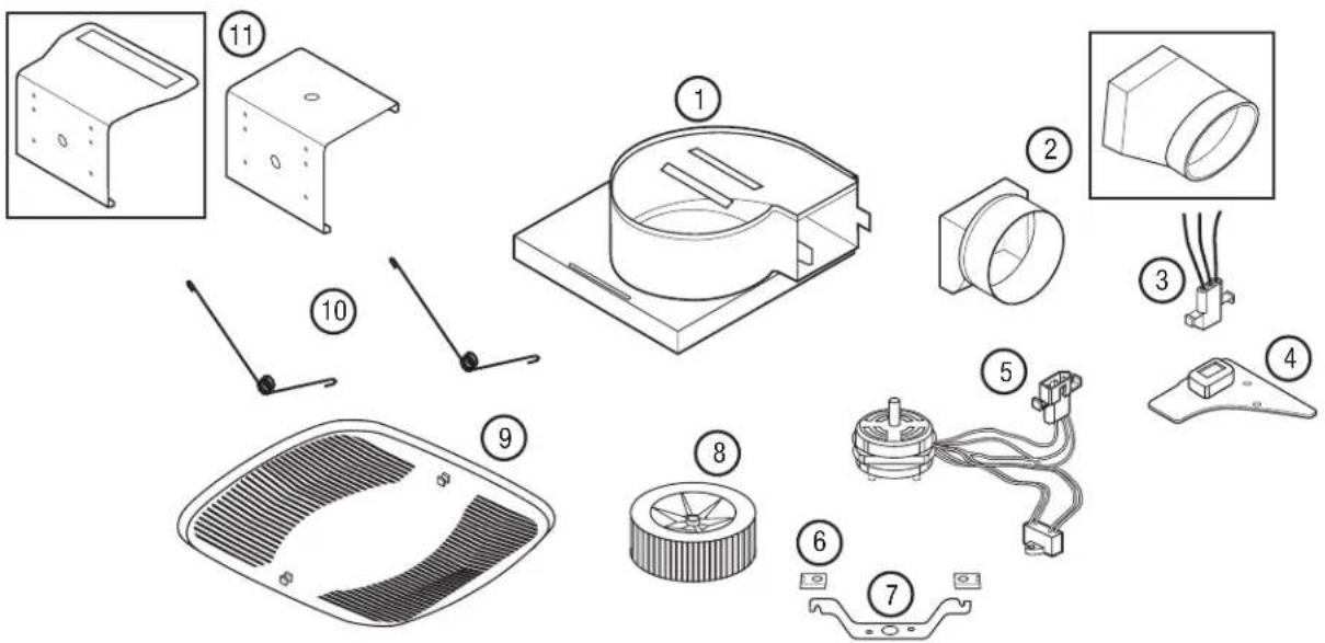
| # Qty. Description Replacement Part # | |||
| 1 1 | Fan Housing | 5S2205001 | |
| 2 | 1 | Damper Assembly - BFQ | 5S2299054 |
| 1 | Damper Assembly - BFQW | 5S2299055 | |
| 3 1 | Receptacle 3P | 5S2205004 | |
| 4 1 | Wire Cover | 5S2205005 | |
| 5 | 1 | Motor - BFQ50, BFQ50W | 5S2205035 |
| 1 | Motor - BFQ60 5S2205036 | ||
| 1 | Motor - BFQ70,BFQ70W | 5S2205037 | |
| 1 | Motor - BFQ75 5S2205037 | ||
| 1 | Motor - BFQ80 5S2205034 | ||
| 1 | Motor - BFQ90 5S2299001 | ||
| # Qty. Description Replacement Part # | |||
| 5 | 1 | Motor - BFQ110 | 5S2205008 |
| 1 | Motor - BFQ140 | 5S2299002 | |
| 6 | 2 | Clip | 5S2205009 |
| 7 1 | Motor Bracket | 5S2299003 | |
| 8 | 1 | Blower Wheel | 5S2299004 |
| 9 | 1 | Grill - BFQ | 5S2205011 |
| 1 | Grill - BFQW | 5S2299056 | |
| 10 | 2 | Grill Springs | 5S2205012 |
| 11 | 1 | Snap In Bracket - BFQ | 5S2205013 |
| 1 | Snap In Bracket - BFQW | 5S2202057 | |
Installer: Installation Date:
Place of Purchase: Model Number:
INSTRUCTIONS IMPORTANTES - MODE D'EMPLOI
Série BFQ et BFQW

natural_image
Simple line drawing of a lever mechanism with a button and handle, labeled Figure 1 (no text or symbols on the diagram itself)natural_image
Diagram of a mechanical assembly with a pin and oval features, labeled Figure 2 (no text or symbols on the diagram itself)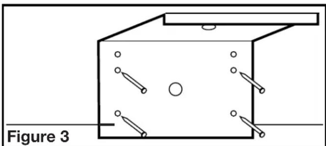
natural_image
Diagram of a 3D container with internal components and labeled Figure 3 (no text or symbols on the diagram itself)
ATTENTION : POUR UNE INSTALLATION APPROPRIÉE, UTILISEZ UN MINIMUM DE 4 VIS SITUÉES DANS LES TROUS LES PLUS PROCHES DES PLAQUES DE PLÂTRE.
natural_image
Technical diagram showing a mechanical assembly with a shaded section and rotation arrow, labeled Figure 4 (no text or symbols on the diagram itself)natural_image
Technical line drawing of a mechanical component with no visible text or symbols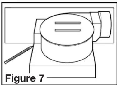
natural_image
Line drawing of a cylindrical object mounted on a base with a pencil, labeled 'Figure 7' (no text or symbols on the object itself)natural_image
Technical diagram of a mechanical assembly with labeled components and cross-section view (no readable text or symbols)


- IMPORTANT INSTRUCTIONS - OPERATING MANUAL
- READ AND SAVE THESE INSTRUCTIONS
- RETAIN INSTRUCTIONS FOR FUTURE REFERENCE.
- GENERAL SAFETY INFORMATION
- SAVE THESE INSTRUCTIONS
- INSTALLATION INSTRUCTIONS
- SECTION 1
- Preparing the Exhaust Fan
- SECTION 2
- New Construction - BFQ Models
- New Construction - BFQW Models (Oval Duct)
- SECTION 3
- Existing Construction - BFQ Models
- Existing Construction - BFQW Models (Oval Duct)
- SECTION 4
- Ducting
- SECTION 5
- SECTION 6
- Completing the Installation
- SECTION 7
- LIMITED WARRANTY
- CUSTOMER SERVICE:
- INSTRUCTIONS IMPORTANTES - MODE D'EMPLOI
Brand : Air King
Model : BFQ70W
Category : Extraction fan