TC90 - Radio Trig Avionics - Free user manual and instructions
Find the device manual for free TC90 Trig Avionics in PDF.

| Product Type | VHF Aviation Radio |
| Brand | Trig Avionics |
| Model | TC90 |
| Power Supply | 10 to 32 V DC (standard avionics) |
| Dimensions (panel) | Approximately 2.5 x 6.25 x 1.5 inches (64 x 159 x 38 mm) |
| Weight | Approximately 0.5 kg |
| Frequency Range | 118.000 to 136.975 MHz (VHF aviation) |
| Frequency Step | 8.33 kHz / 25 kHz (switchable) or 25 kHz / 50 kHz |
| Display | LCD screen with adjustable backlight |
| Main Functions | Flip-flop switching, monitoring (MON), frequency memory (9 slots), GPS database, built-in intercom, dual control |
| Volume and Squelch Control | Rotary knob with push function for automatic squelch |
| Frequency Adjustment | Concentric knobs for MHz and kHz, switchable step |
| Intercom Function | Voice activation (VOX), independently adjustable volume and squelch |
| Configuration Mode | Access by long press on MON, settings: intercom volume, intercom squelch, AUX volume, sidetone, brightness, 8.33 kHz step |
| Dual Control | Two synchronized control panels (except frequency step, brightness, and memory are individual) |
| Warning Messages | Displays WARNING or FAULT (overheating, stuck mic, low voltage, loss of connection, radio failure) |
| Safety | Automatic shutdown after 35 seconds if PTT stuck in transmit position |
| Operating Temperature | -20°C to +55°C (display may be affected at low temperature) |
| Maintenance and Cleaning | Clean with a soft dry cloth. Avoid aggressive liquids and solvents. |
| Spare Parts and Repairability | Repairs by an approved aeronautical maintenance center. No spare parts provided. |
Frequently Asked Questions - TC90 Trig Avionics
User questions about TC90 Trig Avionics
0 question about this device. Answer the ones you know or ask your own.
Ask a new question about this device
Download the instructions for your Radio in PDF format for free! Find your manual TC90 - Trig Avionics and take your electronic device back in hand. On this page are published all the documents necessary for the use of your device. TC90 by Trig Avionics.
USER MANUAL TC90 Trig Avionics
TY91 and TY92 VHF Radio Operating Manual

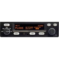
text_image
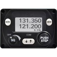
MON 131.350 121.200 8.33k OFF SQ COM ↓ ↑ MEM PUSH STEP00840-00-AD
26 November 2014
Trig Avionics Limited
Heriot Watt Research Park
Riccarton, Edinburgh
EH14 4AP
Scotland, UK
© Copyright 2012, 2013, 2014
EN / DE / FR
EN
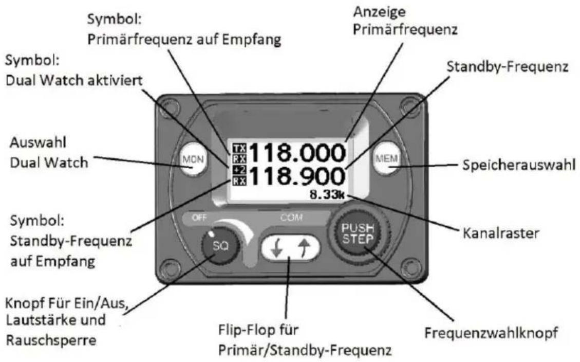
Front Panel
text_image
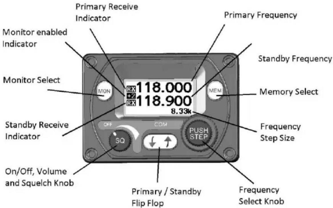
Primary Receive Indicator Monitor enabled Indicator Monitor Select MON 118.000 +2 RX 118.900 8.33k Primary Frequency Standby Frequency Memory Select MEM Standby Receive Indicator OFF COM SQ PUSH STEP Frequency Step Size On/Off, Volume and Squelch Knob Primary / Standby Flip Flop Frequency Select KnobDisplay
The display shows the primary and standby frequencies and a series of icons to indicate the operating mode of the radio.
The primary frequency is at the top and the standby frequency is at the bottom half of the screen. The TX icon shows that the radio is transmitting. An RX icon shows that the frequency is active and the audio will be heard through the headphone and speaker outputs. The standby frequency will only be received during the MONITOR function which is indicated by a +2 icon when active.
The bottom right hand side indicates what frequency step size is selected.
On/Off, Volume and Squelch Knob
The left hand knob controls the power to the VHF radio, adjusts the audio volume, and controls the squelch. Turning this knob clockwise will switch on the radio and then increase the volume. Turning anticlockwise will reduce the volume and eventually will click off.
Pressing this knob toggles the automatic squelch on and off, which can be used to listen for faint stations and as a simple audio test.
Tuning Knobs
The right hand concentric knobs are used to tune the radio. The large knob adjusts the MHz portion of the standby frequency, and the smaller knob adjusts the kHz portion of the standby frequency.
EN
Pressing the end of the small knob changes the channel spacing that the small knob operates through. If the radio is configured for 8.33 kHz operation, the steps toggle between 8.33 kHz channels and 25 kHz channels. If the radio is configured only for 25 kHz operation, the steps toggle between 25 kHz and 50 kHz channels.
Changing the step size does not change the behaviour of the radio, only the tuning knob step size – it helps to quickly tune a frequency.
Flip-flop Button
The flip-flop button swaps the frequency in the standby position into the active position, and moves the active frequency to the standby position.
MON Button
The VHF radio includes a dual-frequency listen feature; pressing the MON button toggles this feature on and off.
When the monitor is active, a +2 icon appears next to the standby frequency, and the radio will scan between the active and standby frequencies listening for transmissions. The primary channel has priority – a transmission on the primary channel will interrupt the secondary channel. As an aid to identifying which channel is active, the RX icon will light next to the active channel and the secondary channel will appear slightly quieter than the primary.
This is useful in an aircraft with only a single radio since it allows you, for example, to copy the ATIS whilst maintaining a listening watch on the ATC frequency.
Remote Frequency Database
If a compatible GPS is connected, the controller will be loaded with airport frequencies from the GPS database. These frequencies are accessed by pressing the MEM button. The airport frequencies and selection order are determined by the data sent to the controller from the GPS.
text_image
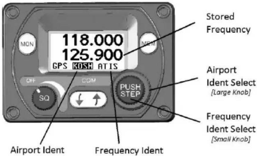
118.000 125.900 GPS KOSH ATIS Stored Frequency OFF COM SQ PUSH STEP Airport Ident Select [Large Knob] Frequency Ident Select [Small Knob] Airport Ident Frequency IdentEN
The available airports can be scrolled through using the large frequency select knob. The individual frequencies associated with that airport can be scrolled through by using the smaller frequency select knob. After you have stepped through all the loaded airports, or if there is no GPS attached, the built-in memory of the controller will be displayed.
In each case the selected frequency is loaded into the standby position.
Pressing MEM again leaves the stored frequency in the standby window.
Pressing the Flip-flop button loads the stored frequency directly into the active channel.
Note: When the controller is displaying the available airport frequencies it will not accept any new updates from the GPS to avoid the frequencies changing during selection. To allow the GPS to update the available frequency database you must come out of memory mode by pressing the MEM or flip-flop button.
Frequency Memory
If no GPS is connected and the MEM button is pressed, or if the large knob is rotated beyond the remote database the controller will access the internal quick reference memory. There are 9 quick reference memory locations and the bottom edge of the screen will display which memory location is currently selected (1 – 9).
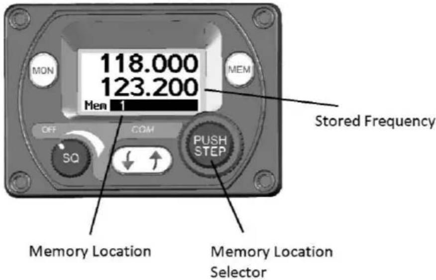
text_image
MON 118.000 123.200 Mem 1 OFF COM SQ PUSH STEP Stored Frequency Memory Location Memory Location SelectorRotating the small frequency selector knob will step through the memory locations. The standby frequency window will display the stored frequency. To store a frequency in one of the memory locations it must first be tuned and active as the primary frequency. Press MEM to enter the memory mode in the usual way. Select the channel you want to overwrite with the tuning knobs.
EN
Now press, AND HOLD, the MEM button for 2 seconds. The current active frequency will be moved to the selected memory location, overwriting the existing contents.
Intercom Function
The TY91/TY92 radio has a built in intercom which can be installed as permanently engaged or selected via a switch. The intercom is voice activated and the audio is routed through to both of the headsets. The intercom squelch and volume can be adjusted independently from the radio function through the configuration menu.
Stuck Mic
If the PTT switch is stuck in the ON or transmit position, the radio will automatically cut out after 35 seconds as a safety measure.
Configuration Mode
Additional setup items can be accessed by holding down the MON button for 5 seconds. The menu options can be selected using the larger inside tuning knob and the parameter value can be altered using the smaller outside tuning knob.
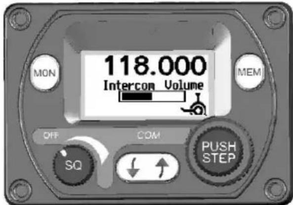
text_image
MON 118.000 Intercom Volume MEM OFF COM SQ PUSH STEP| Intercom Volume | Sets the intercom volume level |
| Intercom Squelch | Sets the sensitivity of the intercom voice operated squelch |
| AUX In Volume | Sets the volume level of the auxiliary input |
| AUX In Mute | Mutes the auxiliary audio when a VHF transmission is received by the radio |
| Sidetone Volume | Sets the volume level of sidetone heard when transmitting |
| Radio Squelch | Sets the sensitivity of the radio squelch |
| Enable 8.33 kHz | Sets the frequency step size to 8.33/25 kHz or 25/50 kHz |
EN
Brightness
Sets the LCD backlight brightness
Dual Control Operation
If two control heads are installed for a dual control setup then changes made to one controller will be automatically updated on the second controller. There is a small time lag between operating one controller and updating the display on the second controller. This is purely a delay in the display and there is no delay in the tuning or operation of the TY91/TY92 radio.
The exception is that the radio volume knob works on a “loudest wins” basis. The radio volume will always correspond to the control head that has the volume knob set to the highest position. This means that only one of the controllers needs to be turned up to operate the radio normally, for example when flying a tandem aircraft solo.
Dual Control Individual Functions
The following functions are local to the individual control head and will not automatically update or transfer between two controllers:
Frequency Step Size
Changing the frequency step size by pressing the PUSH/STEP button on one controller does not affect the other controller.
Brightness
The brightness is separately adjusted on each controller.
Memory
The frequencies stored in the memory are local to each controller. The memory data is not transferred between controllers, although a frequency selected from the memory will appear on the screen on the other controller.
General Low Temperature Operation
The TY91/TY92 is certified to operate correctly down to -20^ , but at low temperatures the controller display may be impaired. On a cold day you may need to wait for the cockpit to warm up to ensure normal operation.
Warning Messages
If the VHF radio detects a problem, the screen will indicate WARNING and a brief statement of the problem. Depending on the nature of the problem, your VHF radio may not be working properly. Note the message on the screen and pass that information to your avionics maintenance organisation. Press the flip-flop button to clear the message.
EN
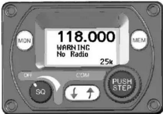
text_image
MON 118.000 WARNING No Radio 25k OFF COM SQ PUSH STEPThe following warnings may be seen:
Remote Hot The remote radio is overheating.
Stuck Mic The PTT switch has been closed for more than 35 seconds.
Low Volts The aircraft power input is below 10 volts (TY91) or 16 volts (TY92).
No Radio Connection between the controller and the remote radio has been lost.
Radio Fault The remote radio is reporting an unspecified fault.
Fault Annunciation
If the VHF radio detects a catastrophic internal failure, the screen will indicate FAULT and a brief statement of the problem. Note the FAULT message at the bottom of the screen and pass that information to your avionics maintenance organisation. The fault may be cleared by re-cycling the power to the radio but if the fault is still present the message will reappear.
Dual Control Warnings and Fault Annunciations
In a dual control head installation, any warning or fault annunciation will be displayed on both controllers. If one of the controllers suffers a failure, the second controller may still continue to control the radio. The fault should be investigated and rectified as soon as possible. It is not advisable to continue to operate a dual control setup with only one controller operational.
DE
Bedienelemente
Heriot Watt Research Park
Riccarton, Edinburgh EH14 4AP, UK
Tel: +44 (0)131 449 8810
Fax: +44 (0)131 449 8811
support@trig-avionics.com
www.trig-avionics.com