OB5013 - Amplifier IFM - Free user manual and instructions
Find the device manual for free OB5013 IFM in PDF.



| Product Type | Fiber optic amplifier |
| Brand | IFM |
| Model | OB5013 |
| Category | Amplifier |
| Power Supply | DC (PNP or NPN depending on wiring) |
| Output | Switching (PNP/NPN) and diagnostic output (10 mA max) |
| Range | Variable depending on the fiber optic used |
| Pulse extension | 0 or adjustable from 2 to 90 ms |
| Threshold adjustment | Automatic or manual |
| Indicators | Green LEDs (intensity/reserve), red (error), yellow (switching status) |
| Mounting | On DIN rail (standard profile) or mounting bracket |
| Electrical connection | By cable (BN, BU, BK, VT) according to diagram |
| Protection | IP65 (cover closed) |
| Operating temperature | Not specified, standard industrial use |
| Weight | Approximately 150 g (estimated) |
| Dimensions | Not specified, suitable for 35 mm DIN rail |
| Maintenance | Clean fiber optics if dirty; check LED status |
| Safety | Disconnect power before connection; avoid short circuits |
| Spare parts | Compatible FE-11 and FT-11 fiber optics |
| Repairability | Not repairable by user; contact ifm support |
Frequently Asked Questions - OB5013 IFM
User questions about OB5013 IFM
0 question about this device. Answer the ones you know or ask your own.
Ask a new question about this device
Download the instructions for your Amplifier in PDF format for free! Find your manual OB5013 - IFM and take your electronic device back in hand. On this page are published all the documents necessary for the use of your device. OB5013 by IFM.
USER MANUAL OB5013 IFM
natural_image
Technical line drawing of a mechanical component with threaded end and mounting holes (no text or symbols)Deutsch
| Intended use E1Controls and indicators E1MountingMount the fibre optics E2Electrical connection E2Automatic setting of the switching threshold (1) E3Automatic setting of the switching threshold (2) E4Manual setting of the switching threshold (1) E5Manual setting of the switching threshold (2) E6Adjust of the pulse stretching E7Operation | E2 |
| E7 |
Français
The switching amplifier senses objects and materials without contact and indicates their presence by a switching signal.
- Only for the connection of the ifm fibre optics type FE-11 and FT-11.
- Sensing range depends on the fibre optic.
- Pulse stretching 0 or adjustable between 2 and 90ms.
(Each input pulse is stretched to the set value).

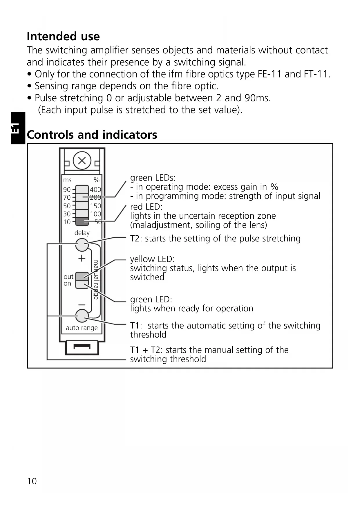
Controls and indicators

green LEDs:
- in operating mode: excess gain in %
- in programming mode: strength of input signal red LED:
lights in the uncertain reception zone (maladjustment, soiling of the lens)
T2: starts the setting of the pulse stretching
yellow LED:
switching status, lights when the output is switched
green LED:
lights when ready for operation
T1: starts the automatic setting of the switching threshold
T1 + T2: starts the manual setting of the switching threshold
Mounting
Mount the unit on a DIN rail or by means of a mounting fixture.
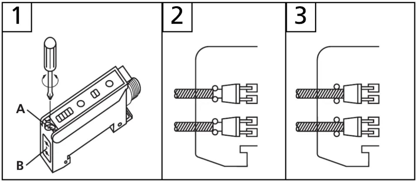
Mount the fibre optics:
- Loosen the screw A, fig. 1.
- Place the fibre optics into the sensor holes B until you feel a slight resistance (O ring), fig. 2.
- Push the fibre optics until they come to a stop (optical elements) and hold them, fig. 3.
- Tighten the screw A.

If the fibre optics are not in contact with the optical elements, the sensing range is reduced.
Electrical connection

Isolate the power, then connect the unit as specified (see the last page or the type label).
- Core colours (for sensors with cable connection): BN = brown, BU = blue, BK = black, VT = violet.
- Programming of the output function by wiring (see the last page or the type label).
- Load of the function check output (fc-output): max. 10mA.
Automatic setting of the switching threshold (1)
- Objects move through the detection area
- Diffuse reflection fibre (FT ...) and through-beam fibre (FE ...)
The unit detects input signals of various intensity in any sequence and calculates the optimum switching threshold.

| 1 | Allow the objects to pass trough the detection area. Press until the row of LEDs flashes. Press until the row of LEDs flashes. | → |  Yellow and green LEDs flash alternately (= unit is in the programming mode). Yellow and green LEDs flash alternately (= unit is in the programming mode). |
| 2 |  Press once. Press once. |  | Yellow and green LEDs go out for a short time, then flash again alternately. |
| 3 |  Press once. Press once. |  | Yellow and green LEDs go out for a short time, | |
 | then the green LED is on (= unit is in the operating mode). |

If the setting of the switching threshold is not possible (e.g. object signal and background signal are about the same), the row of LEDs flashes after step 3. The unit then passes into the operating mode with the switching threshold being unchanged.
Automatic setting of the switching threshold (2)
- Stationary objects
- Diffuse reflection fibre (FT ...) and through-beam fibre (FE ...)
The unit detects input signals of various intensity in any sequence and calculates the optimum switching threshold.
| 1 |  Press until the row of LEDs flashes. Press until the row of LEDs flashes. |  | Yellow and green LEDs flash alternately(= unit is in the programming mode). |
| 2 | Place the object into the detection area.* Press once. Press once. | 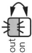 | Yellow and green LEDs go out for a short time, then flash again alternately. |
| 3 | Remove the object.* Press once. Press once. |  | Yellow and green LEDs go out for a short time, | |
 | then the green LED is on (= unit is in the operating mode). |
* You can also proceed in reverse order: first setting without the object, then with the object.

If the setting of the switching threshold is not possible (e.g. object signal and background signal are about the same), the row of LEDs flashes after step 3. The unit then passes into the operating mode with the switching threshold being unchanged.
Manual setting of the switching threshold (1)
- Stationary objects / Diffuse reflection fibre (FT ...)

| 1 |  Press until the row of LEDs flashes. Press until the row of LEDs flashes. | Green LED flashes,yellow LED indicates theswitching status(= unit is in theprogramming mode). | |
| 2 | Place the object into the detection area. | 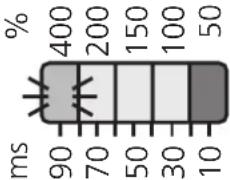 Object signal is measured and indicated (= row of dimly lit LEDs)brightly flashing LED = current switching threshold. Object signal is measured and indicated (= row of dimly lit LEDs)brightly flashing LED = current switching threshold. | |
| 3 | Remove the object. |  Background signal is measured and indicated(= row of dimly lit LEDs). Background signal is measured and indicated(= row of dimly lit LEDs). | |
| 4 |  Press the "+" or "-" button until the switching threshold is in the middle between the background signal and the object signal;(here: reducing the switching threshold). Press the "+" or "-" button until the switching threshold is in the middle between the background signal and the object signal;(here: reducing the switching threshold). |  | |
| 5 | 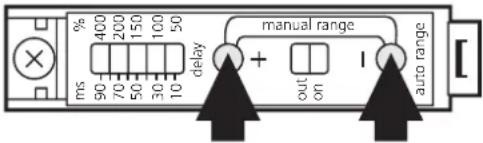 Press until the row of LEDs flashes. Press until the row of LEDs flashes. | Green LED lights(= unit is in the operating mode). |
Manual setting of the switching threshold (2)
- Stationary objects / through-beam fibre (FE ...)
| 1 |  Press until the row of LEDs flashes. Press until the row of LEDs flashes. |  Green LED flashes,yellow LED indicates theswitching status(= unit is in theprogramming mode). Green LED flashes,yellow LED indicates theswitching status(= unit is in theprogramming mode). |
| 2 |  Press the “-” button until the row of LEDs indicates the lowest switching threshold. Press the “-” button until the row of LEDs indicates the lowest switching threshold. |  | 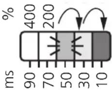 |
| 3 | Place the object into the detection area.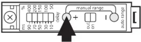 Press the “+” button until the unit switches (yellow LED lights or goes out). Press the “+” button until the unit switches (yellow LED lights or goes out). |  |  | |
 | or  | |||
| 4 |  Press until the row of LEDs flashes. Press until the row of LEDs flashes. |  |  | Green LED lights(= unit is in the operating mode). |
Adjust of the pulse stretching

| 1 | 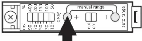 Press until the row of LEDs flashes. Press until the row of LEDs flashes. |  Yellow and green LEDs flash alternately (= unit is in the programming mode). Yellow and green LEDs flash alternately (= unit is in the programming mode). | |
| 2 | 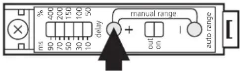 Press the "+" or "-" button to set the desired delay time (here: increasing delay time).1 x = about 1ms; hold the button pressed for fast setting. Press the "+" or "-" button to set the desired delay time (here: increasing delay time).1 x = about 1ms; hold the button pressed for fast setting. |  |  |
| 3 | Wait for approx. 10s. | Green LED lights (= unit is in the operating mode). |
Operation
Only open the cover to make adjustments. Close it after the adjustment has been made in order to maintain the protection IP65.
Check whether the unit functions properly. Indication by LEDs and by the function check output:
- Red LED lights: wrong sensing of the object (maladjustment, soiling of the lens).
- Row of LEDs flashes qickly: output short-circuited / slowly: internal malfunction.
The function check output switches in the case of
- wrong sensing of the object (maladjustment, soiling of the lens), reset after the object has been sensed again properly;
- a short circuit of the switching output, reset about 4s after the fault has been eliminated.
DC NPN + Fiberoptik FT... / + fibre optic FT... / + fibre optique FT...

PIN2 / VT = fc-output

- Controls and indicators
- Mounting
- Mount the fibre optics:
- Electrical connection
- Automatic setting of the switching threshold (1)
- Automatic setting of the switching threshold (2)
- Manual setting of the switching threshold (1)
- Manual setting of the switching threshold (2)
- Adjust of the pulse stretching
- Operation
Brand : IFM
Model : OB5013
Category : Amplifier