
KN5113 - Detector IFM - Free user manual and instructions
Find the device manual for free KN5113 IFM in PDF.

| Product type | Capacitive level detector |
| Brand | IFM |
| Model | KN5113 |
| Category | Detector |
| Power supply | DC 10-30 V, 3-wire |
| Switching output | Normally open (NO) or normally closed (NC), adjustable |
| Connection | Cable or connector, wires BN (brown), BU (blue), BK (black) |
| Housing material | Metal (threaded housing) |
| Thread | M30 (estimation) |
| Weight | Approx. 100 g |
| LED indications | Green (power), yellow (output active), red (error / critical zone) |
| Programming | By push-button, empty/full adjustments, electronic lock |
| Main functions | Level detection of liquids and bulk solids, automatic adjustment |
| Operating mode | High/low level switching depending on mounting |
| Operating temperature | Not specified (estimation -25°C to +70°C) |
| Protection | IP67 (estimation for threaded housing) |
| Maintenance | Cleaning of active face, re-adjustment if dirty |
| Safety | Electronic lock against unintentional programming |
| Repairability | No spare parts, device replacement |
| Documents supplied | User manual (23 pages) |
Frequently Asked Questions - KN5113 IFM
User questions about KN5113 IFM
0 question about this device. Answer the ones you know or ask your own.
Ask a new question about this device
Download the instructions for your Detector in PDF format for free! Find your manual KN5113 - IFM and take your electronic device back in hand. On this page are published all the documents necessary for the use of your device. KN5113 by IFM.
USER MANUAL KN5113 IFM
Adernfarben: BN = braun, BU = blau, BK = schwarz
3 Montage
1 Function and features 9
2 Electrical connection 9
3 Mounting 10
4 Operation 10
5 Programming 10
6 Set-up/operation 14
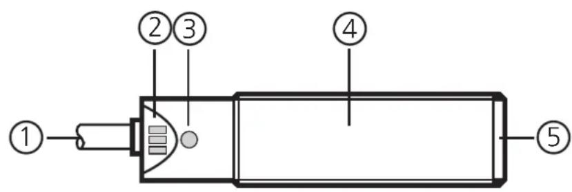
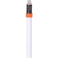
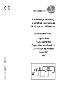
(1) Electrical connection (plug or cable)
(2) LEDs red, yellow, green
(3) Programming button
(4) Threaded sleeve
(5) Active face
1 Function and features
The capacitive level switch monitors levels of liquids and dry bulk material in vessels, preferably plastic granulates. Depending on the setting a switched signal is provided when the current level falls below or exceeds the mounting position.
- Automatic adjustment to the medium to be detected by means of programming button.
2 Electrical connection
Disconnect power before connecting the unit (see type label).
Core colours: BN = brown, BU = blue, BK = black
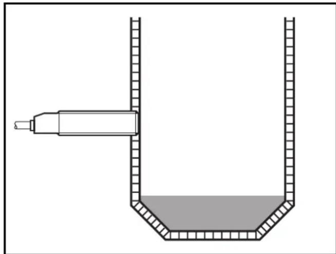
3 Mounting
Mount the proximity switch as shown and then program it.
4 Operation
Adjust the sensor. To do so, press the programming button with a blunt object.
5 Programming
Operating mode
Immediately after power on the proximity switch is in the operating mode. In this mode all normal sensor functions are active.
You can also make the following settings on the unit:
- Adjustment mode
-
Switch point setting by adjustment to the empty and full state.
-
Locking mode
-
Electronic lock to avoid tampering.
-
Setting the output function as normally closed or normally open.
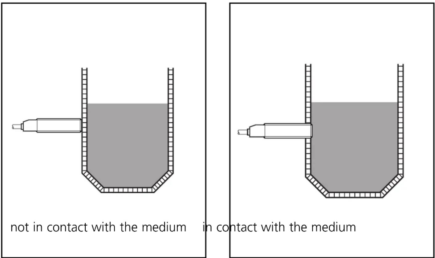
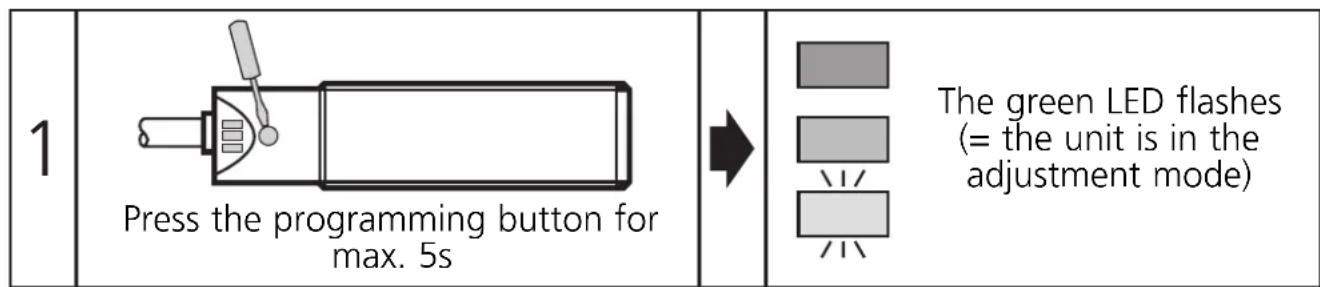
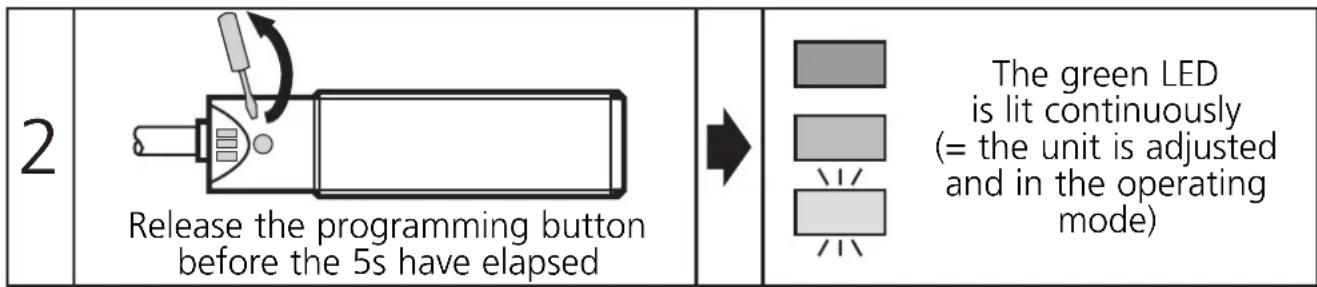
Adjustment mode empty state
The sensor is adjusted to the empty vessel. If it detects material, the switched signal changes.
Then carry out steps 1 and 2.
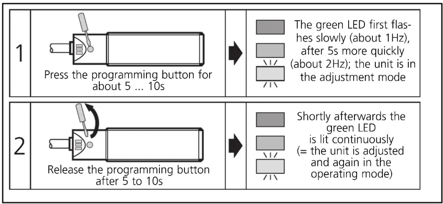
Adjustment mode full state
Fill the vessel so that the sensor detects the material.
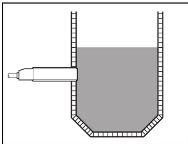
Then carry out steps 1 and 2.
Note:
The adjustment to the full state is not absolutely necessary for the operation of the unit but it is recommended. On the basis of the values for the empty state/full state the internal microprocessor determines the optimum position of the switching thresholds. If you use both adjustment criteria (adjustment to the empty and full state), you obtain the maximum operational reliability for your individual application.
Locking mode
The stored adjustment values can be protected against unauthorised programming as follows (output state not locked):
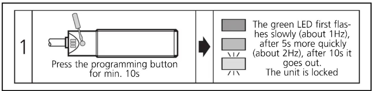
When the programming button is released the unit is locked and all programming functions are inactive. The unit returns to the operating mode.
If this operation starts from the locked state, the green LED does not react at first to avoid any hint to a hidden function.
If you want to release the locking, proceed as follows:
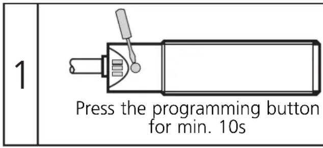
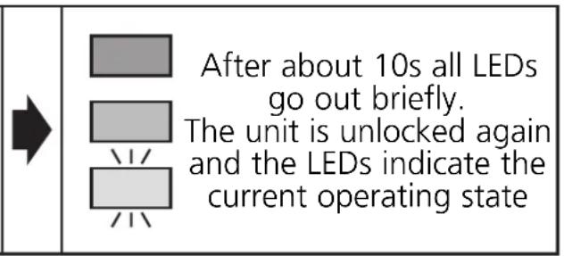
When the programming button is released the unit is unlocked and all programming functions are active again. The unit returns to the operating mode.
Setting the output function as normally closed or normally open
The switching output of the unit can be operated as normally closed or normally open. To do so, the unit must first be disconnected. To generate the inverted output response the operating voltage is connected again by reversing the wires.
Error messages
If the adjustment to the empty or full state is not possible, the red LED flashes quickly after the adjustment attempt (about 2Hz).
To delete this error message press the programming button once or disconnect and then connect power again. The adjustment values successfully read so far remain unchanged.
Possible reasons for an error message:
- The signal difference between the empty and full state is too small (e.g. adjustment to the empty and full state without sufficient change of the level).
-
The signal change between the empty and full state is in the wrong order (e.g. adjustment to the empty state when the vessel is full and then adjustment to the full state when the vessel is empty).
-
Adjustment to the empty state outside the operating range (e.g. adjustment to the empty state with direct contact with an electrically grounded medium, e.g. if the active face is immersed in water).
Help: Avoid the above-mentioned errors and repeat the adjustment.
Further faults:
- Electronic fault or sensing zone of the unit damaged
- Internal fault (can only be deleted by disconnecting and connecting power again, hardware reset).
6 Set-up / operation
Check the safe functioning of the unit. Display by LEDs.
| LED green | ON = unit is ready for operation flashes slowly (1 Hz) = adjustment mode empty state flashes quickly (2 Hz) = adjustment mode full state OFF = locking mode |
| LED yellow | OFF = switching output disabled ON = switching output enabled |
| LED red | flashes quickly (2 Hz) = error message ON = undefined operating range |
| LED yellow and red | flash quickly simultaneously (2Hz) = short circuit of the switching output |
The red LED indicates no malfunction of the unit, it indicates that the internal sensor signal is near the switching threshold.
Two cases can be distinguished:
- Normal operation/safe operation
The red LED is lit temporarily during the change between "medium" and "no medium".
- Warning of possible malfunction
If the red LED is lit continuously, the operating conditions are no longer optimum.
For example a change of the sensing range caused by deposits of dirt can be detected.
You can take preventive measures to avoid a malfunction. For example readjust or clean the unit.
Contenu Page
- Montage
- Function and features
- Electrical connection
- Mounting
- Operation
- Programming
- Operating mode
- Adjustment mode empty state
- Adjustment mode full state
- Note:
- Locking mode
- Setting the output function as normally closed or normally open
- Error messages
- Further faults:
- Set-up / operation
- - Normal operation/safe operation
- - Warning of possible malfunction
- Contenu Page
Brand : IFM
Model : KN5113
Category : Detector