
KG5025 - Proximity sensor IFM - Free user manual and instructions
Find the device manual for free KG5025 IFM in PDF.
| Product type | Capacitive proximity sensor |
| Brand | IFM |
| Model | KG5025 |
| Nominal range (Sn) | 8 mm |
| Detectable materials | Metals, plastics, glass, ceramic, wood, paper, oils, greases, water and aqueous materials |
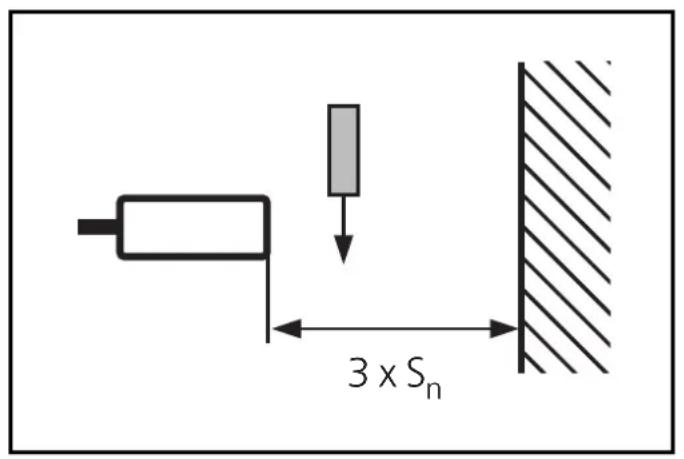
| Mounting | Non-flush, with mounting flange (nuts supplied) |
| Power supply | 10-30 V DC |
| Switching output | Yes (on/off signal) |
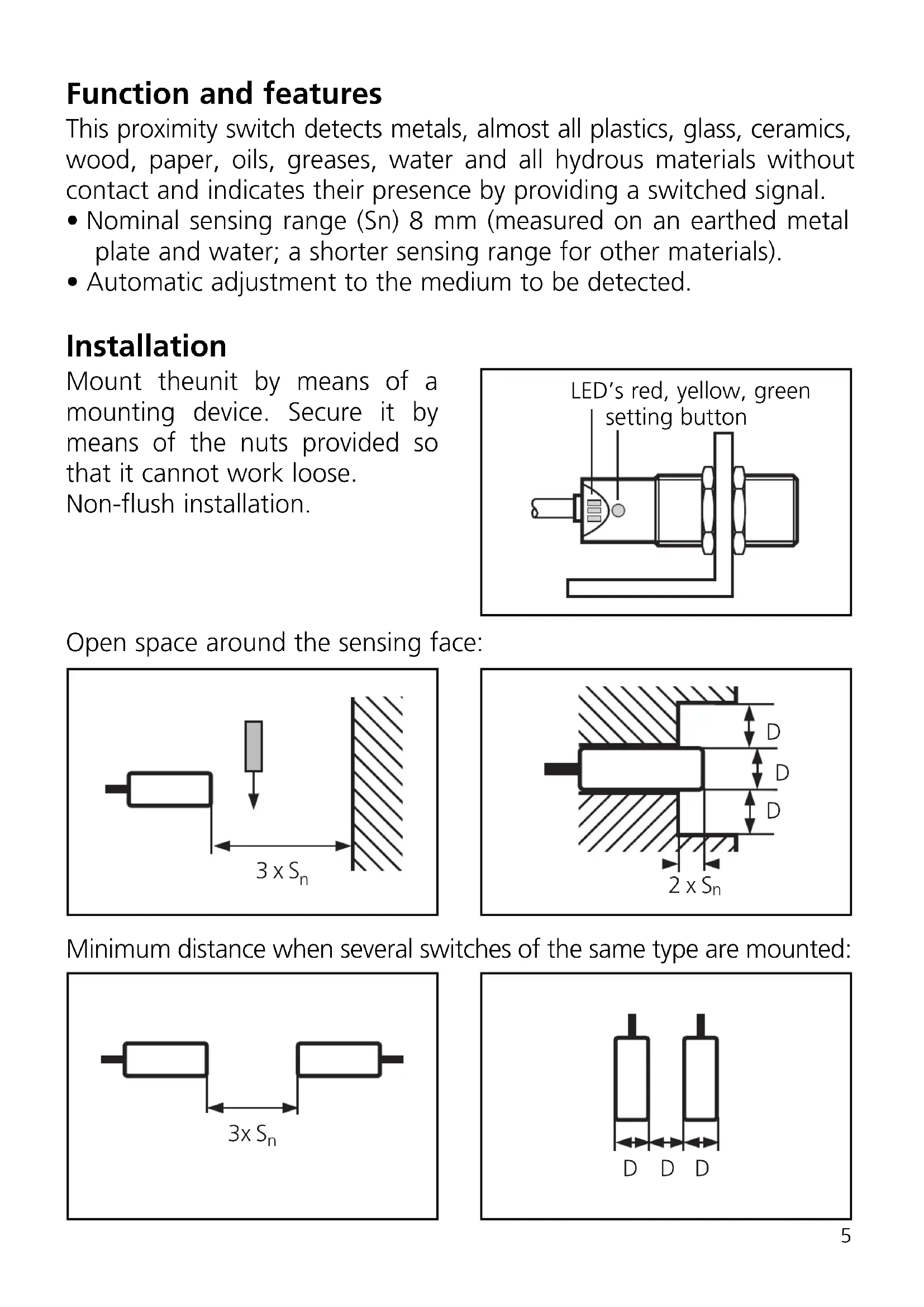
| LED indicators | Green (operational), Yellow (switched output), Red (unsafe zone/error) |
| Setting | Automatic via push-button (threshold programming) |
| Locking/Unlocking | Yes (10-second long press) |
| Electrical connection | 3 wires: brown (BN), blue (BU), black (BK) |
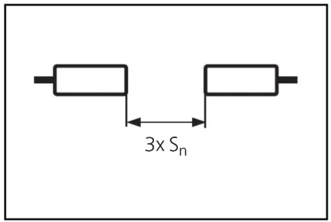
| Clearance zone around the active face | 3 x Sn |
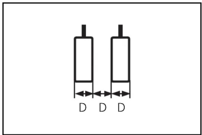
| Minimum distance between sensors (same version) | 3 x Sn |
| Short-circuit protection | Yes (indicated by flashing yellow+red LED) |
| Automatic adaptation | Yes, to the product to be detected |
| Cleaning | Keep the active face free of deposits and foreign bodies |
| Safety | Disconnect the installation from power before connection |
| Manual available | Free PDF (10 pages, French, German, English) |
Frequently Asked Questions - KG5025 IFM
User questions about KG5025 IFM
0 question about this device. Answer the ones you know or ask your own.
Ask a new question about this device
Download the instructions for your Proximity sensor in PDF format for free! Find your manual KG5025 - IFM and take your electronic device back in hand. On this page are published all the documents necessary for the use of your device. KG5025 by IFM.
USER MANUAL KG5025 IFM
Capacitive proximity switch KG/P
natural_image
Technical line drawing of a mechanical component with no visible text or symbolsnatural_image
Pure diagram of a mechanical component with an arrow pointing to it, no text or symbols present.
Betrieb
Function and features
This proximity switch detects metals, almost all plastics, glass, ceramics, wood, paper, oils, greases, water and all hydrous materials without contact and indicates their presence by providing a switched signal.
- Nominal sensing range (Sn) 8 mm (measured on an earthed metal plate and water; a shorter sensing range for other materials).
• Automatic adjustment to the medium to be detected.
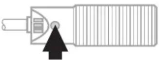
Installation
Mount theunit by means of a mounting device. Secure it by means of the nuts provided so that it cannot work loose. Non-flush installation.
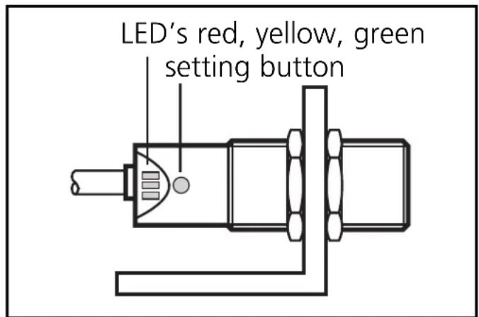
Open space around the sensing face:
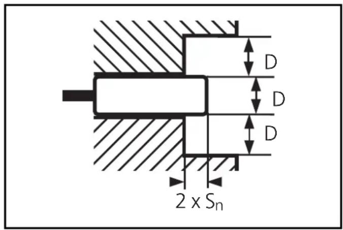
Minimum distance when several switches of the same type are mounted:
Electrical connection

Disconnect power before connecting the proximity switch. Connection strictly to the indications on the type label.
Core colours: BN = brown, BU = blue, BK = black.
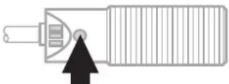
Adjustment
The unit detects the "damped" state (= medium present) and the "undamped" state (= no medium present) and sets the optimum switch point.
| 1 | 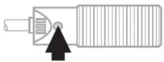 Press for 5s. Press for 5s. |  | Yellow and green LEDs flash alternately (= unit is in the programming mode). |
| 2 | 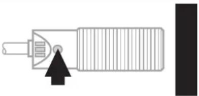 Place the medium into the detection area of the sensor and press the button briefly. Place the medium into the detection area of the sensor and press the button briefly. |  | 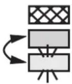 | The yellow and green LED's go out for a short time, then quickly flash alternately;the red LED is on. |
| 3 | 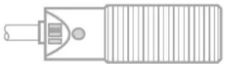 Remove the medium and increase the distance between the medium and the unit until the red LED goes out. Remove the medium and increase the distance between the medium and the unit until the red LED goes out. |  | 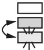 | The yellow and green LED's continue to flash alternately.The red LED goes out. |
If the red LED does not go out, the interval between the "damped" and the "undamped" signals is too short. Press the setting button twice. The unit passes into the operating mode with the switch point being unchanged..
| 4 | 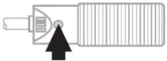 Press briefly. Press briefly. |  |  | The yellow and green LED’s go out for a short time, then the green LED is on (= unit is in the operating mode). |
Steps 2 and 3 can also be taken in reverse order: first align the unit without the medium being present and then place the medium into the detection area until the red LED goes out.

If the setting of the switch point is not possible (the signals for damped/undamped follow too close), the red LED flashes after step 4 (= adjustment error). Press the setting button once. The unit then passes into the operating mode with the switching point being unchanged.
Locking / Unlocking
The unit can be electronically locked to prevent unwanted adjustment of the set parameters:
 Press for 10s. Press for 10s. |  | The yellow and green LED’s flash alternately;after 10s the LEDs go out, the unit is locked. |
natural_image
Pure diagram of a mechanical component with an arrow pointing to it, no text or symbols present.
Operation
Check the safe functioning of the switch.
The operation of the proximity switch is maintenance-free. For perfect functioning make sure that:
- the sensing face and the open space are kept free of deposits and foreign bodies, particularly for installation with the sensing face facing upwards.
LED display:
| LED green lights unit is ready for operation. | |
| LED yellow lights output is switched. | |
| LED red lights uncertain working range. | |
| LED red flashes internal malfunction, adjustment error. | |
| LED's yellow + red | simultaneous flashing: output is short-circuited. |
Brand : IFM
Model : KG5025
Category : Proximity sensor