
OL5020 - Laser pointer IFM - Free user manual and instructions
Find the device manual for free OL5020 IFM in PDF.
| Product type | Laser photoelectric barrier |
| Brand | IFM |
| Model | OL5020 |
| Laser class | 2 (laser class 2 radiation) |
| Range | Indicated on the device label |
| Power supply | 10–30 V DC (typical) |
| Output | PNP or NPN depending on model |
| Output function | Normally closed (NC) or normally open (NO) programmable |
| Diagnostic output | Max load 10 mA |
| LED indicators | Green (ready), Yellow (switching), Red (fault) |
| Sensitivity adjustment | Static or dynamic via teach-in (object / no object) |
| Adjustment aid | Push button on transmitter, temporary beam increase (15 min) |
| Mounting | On mounting bracket, precise alignment of transmitter/receiver |
| Electrical connection | See diagram on page 20 or cell label |
| Maintenance | Clean lenses with a soft cloth, no solvents |
| Safety | Do not look into the light source; affix warning labels |
| Operation | Plug and play, set to maximum range by default |
| Programming mode | Activation by long press (2 s) on push button |
| Reset | In case of internal error: cycle power off and on |
| Housing material | Plastic / metal (typical) |
Frequently Asked Questions - OL5020 IFM
User questions about OL5020 IFM
0 question about this device. Answer the ones you know or ask your own.
Ask a new question about this device
Download the instructions for your Laser pointer in PDF format for free! Find your manual OL5020 - IFM and take your electronic device back in hand. On this page are published all the documents necessary for the use of your device. OL5020 by IFM.
USER MANUAL OL5020 IFM
Through-beam sensor OL laser
natural_image
Technical line drawing of a mechanical sensor or pressure sensor component (no text or symbols)Function and features
The through-beam sensor detects objects and materials without contact and indicates their presence by a switched signal.
Range (r): see type label.

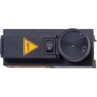
Laser radiation; laser protection class 2.
Do not look directly into the beam!
The enclosed labels (warning laser) must be applied in close proximity to the unit.
Electrical connection

Isolate power, then connect unit (see page 20 or type label).
Load of the function check output (fc output): max. 10mA.
Installation
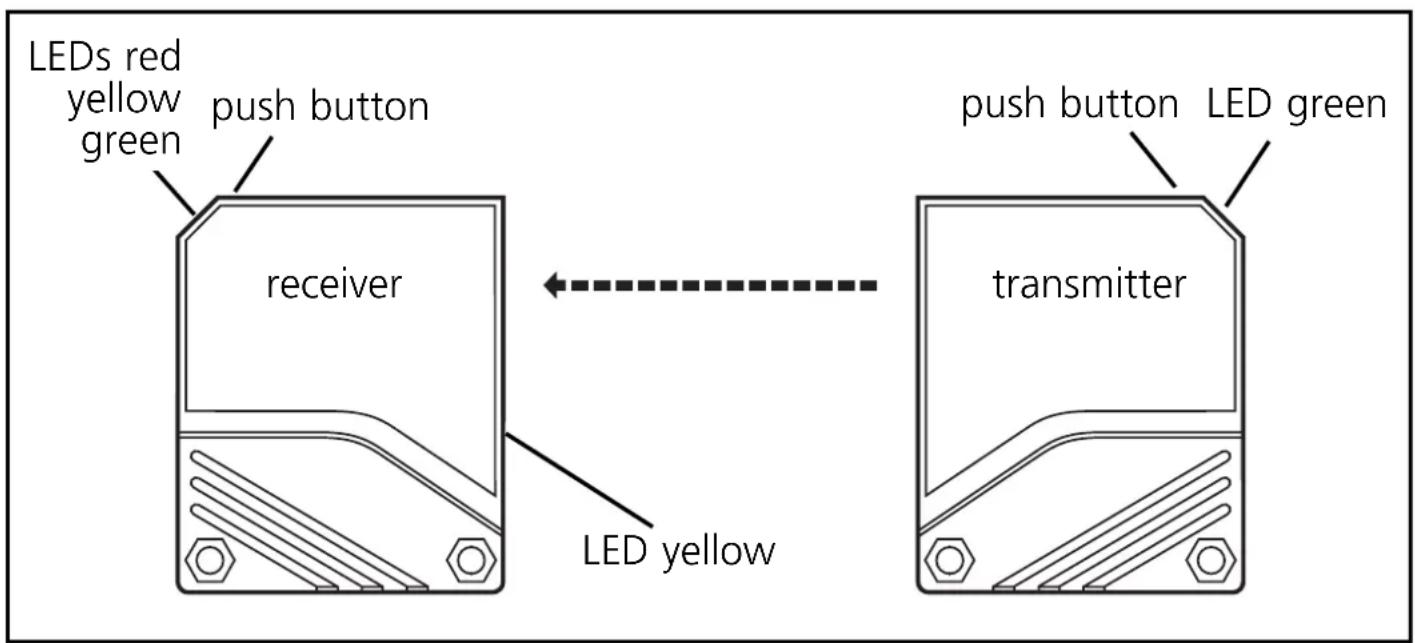
Fix the receiver (type OLE-...) in position. Align the transmitter (type OLS-...) towards the receiver and tighten in the same way. The light spot must hit the receiver lens.
Maximum range is only possible with precise alignment.

Mount the unit so that the mounting position cannot change (in particular avoid high vibrations!). Laser units with a very small light spot diameter are highly focussed; the slightest change in the mounting position will result in misalignment.
Adjustment aid:
For the alignment the transmitter incorporates an adjustment aid. By pressing the setting button on the transmitter the intensity of the transmitted light is increased so that the light spot is clearly visible. After pressing the button again the transmitted light is set again to normal intensity. If the button is not pressed again, the transmitted light is set to normal intensity after about 15 min.
NB: Commissioning
The through-beam sensor is supplied ready to operate (plug and play) set at the max. sensing range. This is sufficient if the through-beam sensor can operate with maximum excess gain (highest contrast). The following setting procedures should only be necessary in less straightforward applications, for example if partly transparent objects must be detected.
Setting of the sensitivity with stationary objects
| 1 | Activate the programming mode of the unit.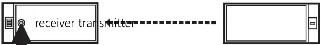 Press for about 2s until the red LED flashes. Press for about 2s until the red LED flashes. |
| The red LED goes out; the yellow and green LEDs flash alternately.The unit is in the programming mode. | |
| 2 | Set the sensitivitywithobject. |
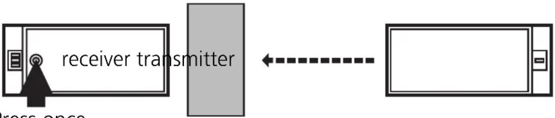 Press once. Press once. | |
| The yellow and green LEDs go out for approx. 1s,then flash again alternately. |
| 3 | Set the sensitivitywithoutobject.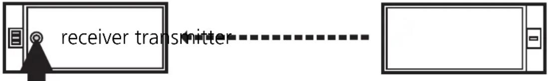 Press once. Press once. |
| The yellow and green LEDs go out for approx. 1s,after approx 3s the green LED is on.The unit is in the operating mode. |
You can also proceed in reverse order: first setting without the object, then with the object.

If the setting of the sensitivity is not possible (e.g. object signal and background signal are about the same), the red LED flashes after step 3 for approx. 2s. The unit then passes into the operating mode with the sensitivity being unchanged.
If the setting button is not activated for 15 minutes during the programming process, the unit passes automatically into the operating mode with the sensitivity being unchanged.
Setting of the sensitivity with moving objects
| 1 | Activate the programming mode of the unit. Press for about 2s until the red LED flashes. Press for about 2s until the red LED flashes. |
| The red LED goes out; the yellow and green LEDs flash alternately.The unit is in the programming mode. |
| 2 | During the measurement (about 1s) allow at least two objects to move through the detection area. |
 Pi Pi | |
| The yellow and green LEDs go out for approx. 1s, then flash again alternately. |
| 3 | During the measurement (about 1s) allow at least two objects to move through the detection area.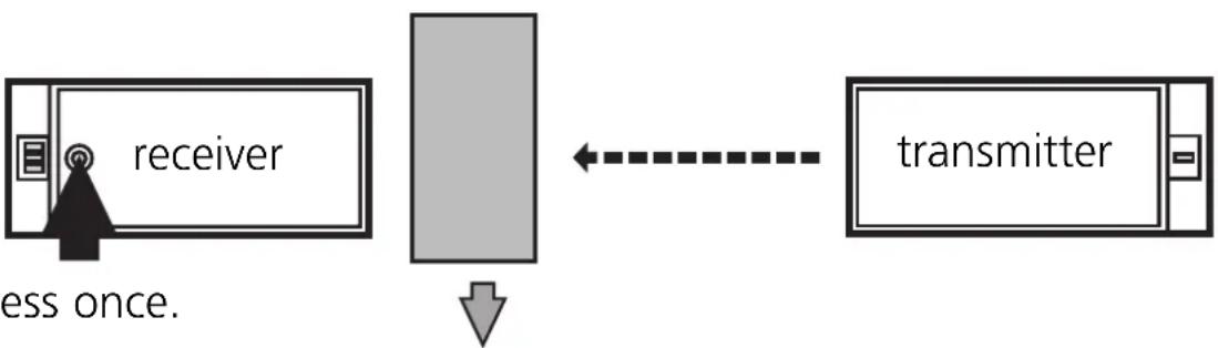 Pr Pr |
| The yellow and green LEDs go out for approx. 1s, after approx. 3s the green LED is on.The unit is in the operating mode. |

If the setting of the sensitivity is not possible (e.g. object signal and background signal are about the same), the red LED flashes after step 3 for approx. 2s. The unit then passes into the operating mode with the sensitivity being unchanged.
If the setting button is not activated for 15 minutes during the programming process, the unit passes automatically into the operating mode with the sensitivity being unchanged.
Setting of the maximum sensitivity
- Go into the programming mode (step 1).
- Interrupt the light beam.
- Press the setting button twice (see steps 2 and 3).
Programming the output function

Press for 10s.

The red LED starts to flash fast after 2s. Then the yellow and green LEDs flash alternately. After 8s all LEDs go off, the output function has changed from light-on mode to dark-on mode (or vice versa).
Operation
Check the safe functioning of the unit. Display by LEDs and by the function check output.
| LED green is lit Unit is ready for operation. | |
| LED yellow is lit Output is switched. | |
| LED red is lit | Error in object detection, e.g. maladjustment, soiling of the lenses. |
| LEDs yellow + red | Flash alternately, 2 Hz: output short-circuited. Flash alternately, 1 Hz: internal malfunction (output is not switched). |
Function check output
- Switches in the case of incorrect object detection (error in object detection, maladjustment, soiling of the lenses) after approx. 4 s, it switches back approx. 4 s after the object is again correctly detected.
- Immediately switches in the case of a short circuit of the switching output, it switches back approx. 2 s after the fault has been rectified.
- Immediately switches in the case of an internal fault, it is only switched back by turning off the operating voltage and then on again.
Maintenance
Keep the plastic lenses of the sensor free from soiling.
For cleaning do not use any solvents or cleaning agents which could damage the plastic lenses.
Sensor with connector
Sensor with connector
Sensor with connector
- Through-beam sensor OL laser
- Function and features
- Electrical connection
- Installation
- Adjustment aid:
- NB: Commissioning
- Setting of the sensitivity with stationary objects
- Setting of the sensitivity with moving objects
- Setting of the maximum sensitivity
- Programming the output function
- Operation
- Function check output
- Maintenance
Brand : IFM
Model : OL5020
Category : Laser pointer