
ST0544 - Detector IFM - Free user manual and instructions
Find the device manual for free ST0544 IFM in PDF.

| Product type | Flow controller (fluid flow detector) |
| Brand | IFM |
| Model | ST0544 |
| Dimensions (approximate) | Length 80 mm, diameter 20 mm |
| Weight (approximate) | 100 g |
| Power supply | Up to 60 V DC (SELV, PELV according to EN50178) |
| Main functions | Fluid flow monitoring, flow detection, output switching (yellow LED), sensitivity adjustment via potentiometer |
| Output type | Switching signal (dry contact) |
| Indicator LEDs | Green (set), Yellow (output switched), Red (not set) |
| Electrical connection | IFM female connector, standard wire colors |
| Installation | Welding an adapter onto the tube, installation with lock nut, O-ring and pressure washer |
| Installation depth | Depending on tube wall thickness (mark flush) |
| Minimum distance | 5 x pipe diameter upstream, 3 x downstream |
| Temperature range | Not specified, but suitable for standard fluids |
| Material | Not specified, probably stainless steel or brass |
| Maintenance and cleaning | Clean the probe tip periodically with a soft cloth; use an acetic cleaning product for stubborn deposits (limescale) |
| Safety | Installation by an electrician, compliance with national and international standards, de-energize before connection |
| Spare parts and repairability | Welding adapter, O-ring, pressure washer, lock nut, potentiometer protective label |
| General information | Manual available as free PDF on notice-facile.com; manufacturer: IFM |
Frequently Asked Questions - ST0544 IFM
User questions about ST0544 IFM
0 question about this device. Answer the ones you know or ask your own.
Ask a new question about this device
Download the instructions for your Detector in PDF format for free! Find your manual ST0544 - IFM and take your electronic device back in hand. On this page are published all the documents necessary for the use of your device. ST0544 by IFM.
USER MANUAL ST0544 IFM
natural_image
Technical line drawing of a mechanical component with threaded shaft and bolt (no text or symbols)Maßzeichnung
Scale drawing
Dimensions
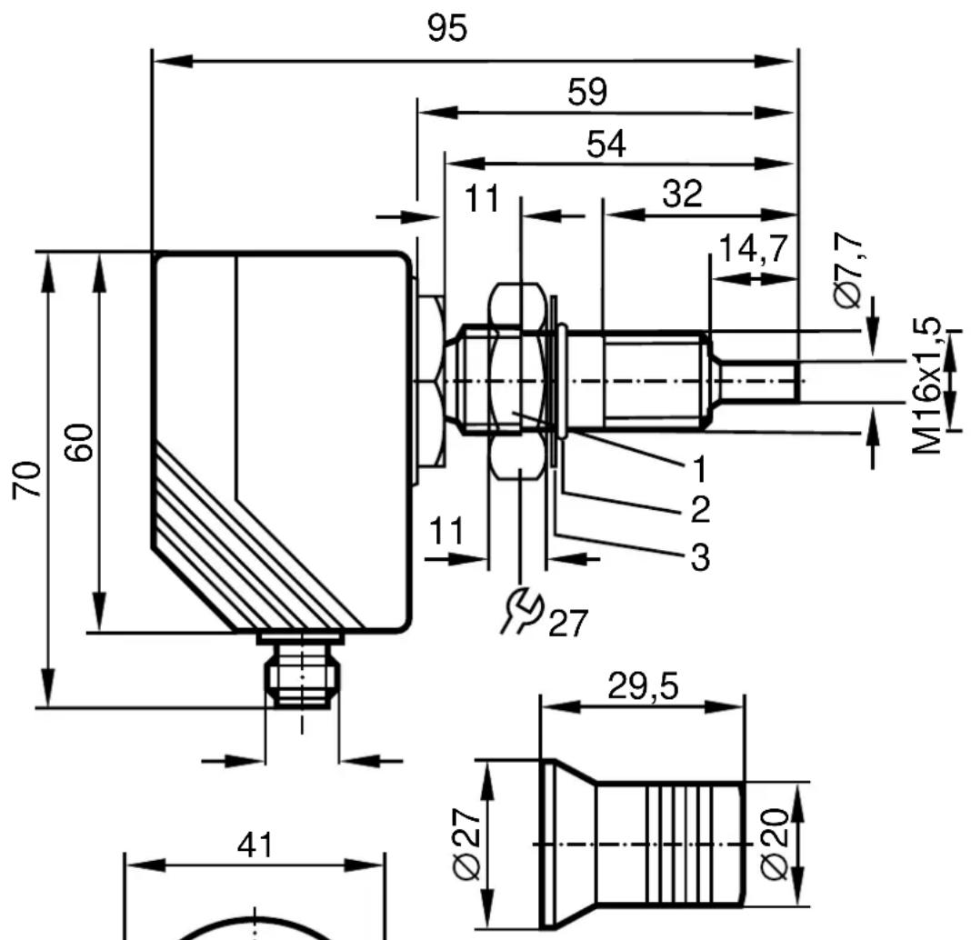
1 = M18 x 1,5
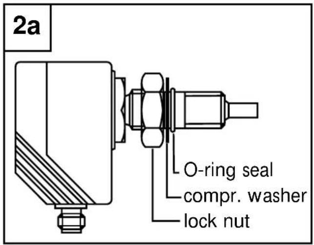
2 = O-Ring
3 = Druckscheibe
1 = M18 x 1.5
2 = O-ring seal
3 = compr. washer
1 = M18 × 1,5
2 = joint torique
3 = rond. de pression
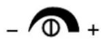
Anschlußschema
Wiring
ST0544
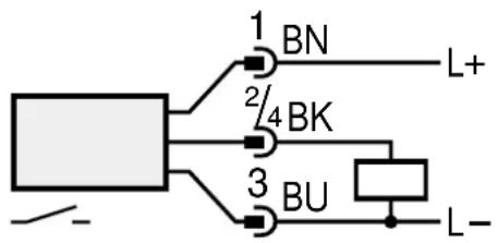
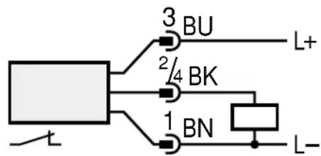
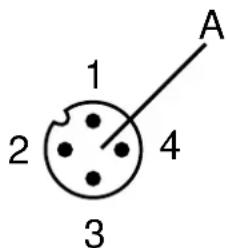
1 = BN (braun), 2 = WH (weiß), 3 = BU (blau), 4 = BK (schwarz).
A = connector view (sensor)
n.c. = not connected
Core colours of ifm sockets:
1 = BN (brown), 2 = WH (white), 3 = BU (blue), 4 = BK (black).
1 = BN (brun), 2 = WH (blanc), 3 = BU (bleu), 4 = BK (noir).
natural_image
Mechanical assembly diagram showing a bolt and shaft with rotational motion arrows (no text or symbols)natural_image
Pure diagram of a battery with internal circuit lines and no text or symbolsFunction and features
The flow monitor monitors liquid media. It senses whether there is a preset flow (= medium flows) or not (= medium does not flow) and provides a switching signal.
Installation
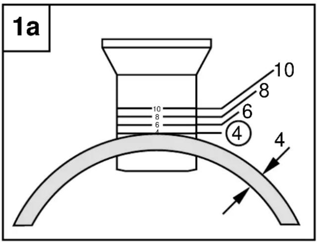
- Weld the adapter into the pipe. The installation depth depends on the pipe wall thickness. The bush should be inserted so that the figure corresponding to the wall thickness is flush with the outside pipe wall and can be seen from all sides (fig. 1a).
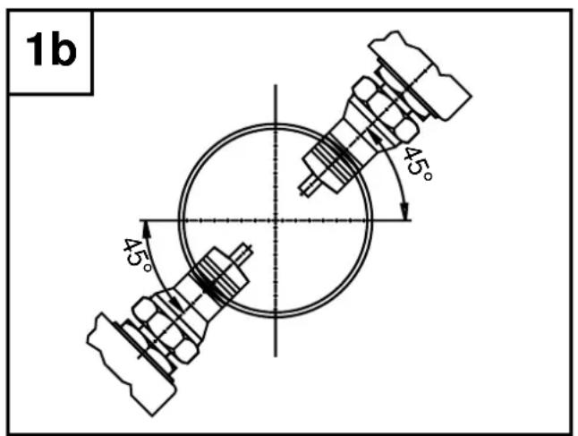
In the case of horizontal pipes the bush should be welded at an angle of 45^ (fig. 1b).
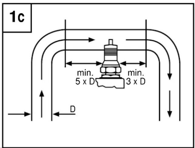
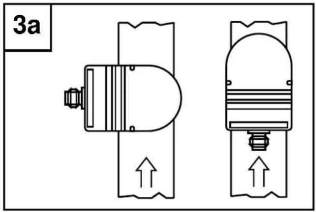
To avoid malfunction a minimum distance between the flow monitor and bends, valves or such like must be observed (fig. 3).
- Min. 5 x pipe diameter upstream,
- Min. 3 x pipe diameter downstream.
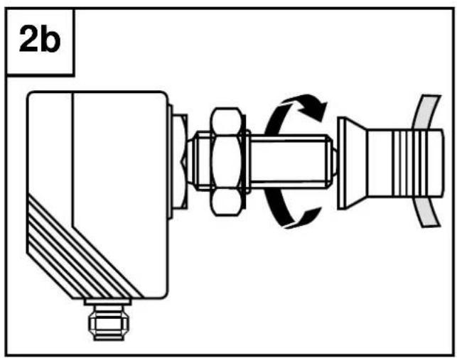
- Insert the flow monitor into the bush by means of lock nut, O-ring seal and compression washer and screw it in completely using the full thread (fig. 2a, 2b).
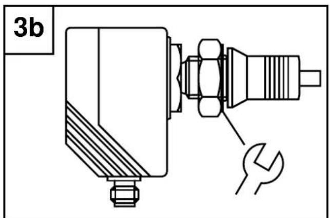
- Position the flow monitor (in the longitudinal pipe axis or transverse to it, fig. 3a) and fasten the lock nut (fig. 3b).
Electrical connection
The unit must only be mounted by an electrician.
The national and international regulations for the installation of electrical equipment must be observed.
Voltage supply for units up to 60 V to EN50178, SELV, PELV.
Isolate power, then connect the unit (see page 3 or type label).
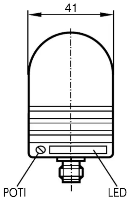
Adjustment
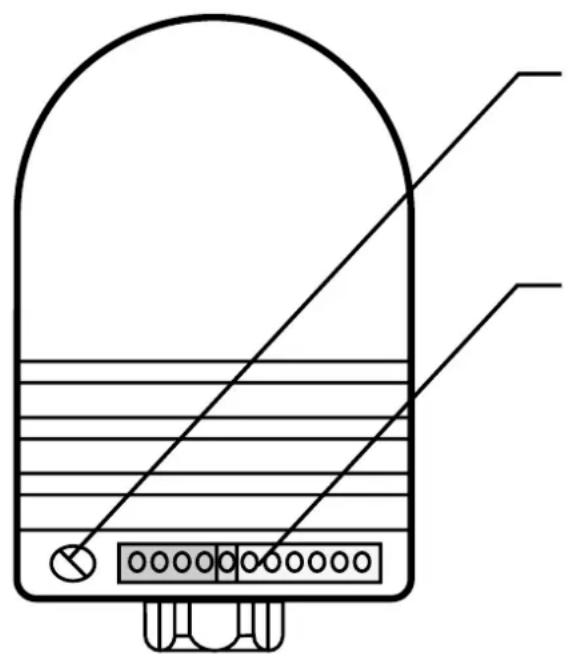
natural_image
Diagram of a battery with internal circuit lines and terminal blocks (no text or symbols)setting potentiometer sensitivity
chain of LED's
- red LED lights: the unit is not adjusted
- yellow LED lights: the output is switched
-
green LED lights: the unit is adjusted
-
Apply the operating voltage. Switch on the flow (preset value) and keep it constant.
The yellow LED lights; the output is switched for about 20s (power-on delay time).
- Turn the pot until one green LED comes on. The farther the green LED is away from the yellow LED, the safer is the adjustment (excess gain for flow or temperature fluctuations).
- Conceal the pot after adjustment by the label provided to protect it against unauthorised tampering.
Operation
After mounting, wiring and setting check whether the unit operates correctly.
Recommended maintenance
Check the sensor tip for build-up from time to time. Clean it with a soft cloth. If necessary, build-up which adheres firmly (e.g. lime) can be removed with a common vinegar cleansing agent.
The units are suitable for use in moderate electromagnetic fields (see table). When operating ISM equipment or powerful walkie-talkies in the vicinity of the units additional measures to avoid malfunction can be required.
| Noise immunity Standard Severity level | ||
| ESD | IEC 1000-4-2 / EN 61000-4-2 | 4 kV CD / 8 kV AD |
| HF radiated | IEC 1000-4-3 / EN 61000-4-3 | 3 V/m; 80 ... 1000 MHz |
| Burst | IEC 1000-4-4 / EN 61000-4-4 | 2 kV coupling pliers |
| HF conducted | IEC 1000-4-6 / EN 61000-4-6 | 3 V; 0.15 ... 80 MHz |
natural_image
Technical diagram of a mechanical assembly with rotating components (no text or symbols)natural_image
Diagram of a battery with internal circuit lines and terminal blocks (no text or symbols)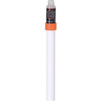

Brand : IFM
Model : ST0544
Category : Detector