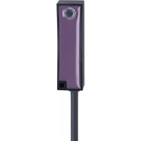
EC2061 - Tilt sensor IFM - Free user manual and instructions
Find the device manual for free EC2061 IFM in PDF.


User questions about EC2061 IFM
0 question about this device. Answer the ones you know or ask your own.
Ask a new question about this device
Download the instructions for your Tilt sensor in PDF format for free! Find your manual EC2061 - IFM and take your electronic device back in hand. On this page are published all the documents necessary for the use of your device. EC2061 by IFM.
USER MANUAL EC2061 IFM
Operating instructions Inclination switch
EC2061
EC9203
Contents
1 Safety instructions.... 3
2 Preliminary note 4
3 Symbols used 5
4 Intended use.... 6
5 Installation.... 7
5.1 Mounting surface 7
5.2 Fastening 7
6 Electrical connection.... 8
7 Operation 9
7.1 Switching characteristics.... 10
8 Maintenance, repair and disposal 11
1 Safety instructions
- The unit described is a subcomponent for integration into a system.
- The system architect is responsible for the safety of the system.
-
The system architect undertakes to perform a risk assessment and to create documentation in accordance with legal and normative requirements to be provided to the operator and user of the system. This documentation must contain all necessary information and safety instructions for the operator, the user and, if applicable, for any service personnel authorised by the architect of the system.
-
Read this document before setting up the product and keep it during the entire service life.
- The product must be suitable for the corresponding applications and environmental conditions without any restrictions.
- Only use the product for its intended purpose (→ Intended use).
- If the operating instructions or the technical data are not adhered to, personal injury and/or damage to property may occur.
- The manufacturer assumes no liability or warranty for any consequences caused by tampering with the product or incorrect use by the operator.
- Installation, electrical connection, set-up, operation and maintenance of the product must be carried out by qualified personnel authorised by the machine operator.
- Protect units and cables against damage.
2 Preliminary note
You will find instructions, technical data, approvals, accessories and further information using the QR code on the unit / packaging or at www.ifm.com.
3 Symbols used
√ Requirement
Instructions
Reaction, result
[...] Designation of keys, buttons or indications
→ Cross-reference

Important note
Non-compliance may result in malfunction or interference.

Information
Supplementary note
4 Intended use
The inclination switches are designed for horizontal mounting.
They measure the angle of inclination in the vertical plane (around the Z-axis of the sensor).
They enable precise spatial monitoring of an object and measure its position in relation to the gravity of the earth without contact.

The device is only designed for use as a switch with normally open function.
▷ The switch only works in the orientation described in the chapter → Installation.
▷ No warranty is given for incorrect or improper use.
5 Installation
5.1 Mounting surface
▶ Mount the device on a flat mounting surface.
▷ The housing must not be exposed to any torsional forces or mechanical stress.
5.2 Fastening

▶ Secure the device with an M6 screw through the metal socket provided for this purpose.
▶ If necessary, use the smaller hole for additional fastening (e.g. with a metal bolt).
▶ Install the device so that the potting side faces outwards and the reference level (1) is on the mounting surface (2).
6 Electrical connection

The unit must be connected by a qualified electrician.
▶ Observe the national and international regulations for the installation of electrical equipment.
▶ Disconnect power.
▶ Connect the unit as follows:
EC2061
| Designation | Core colour | Potential | |
| Operating voltage | black (BK) | 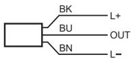 | 8...30 V DC |
| Mass | brown (BN) | GND | |
| Digital output (normally open) | blue (BU) | - | |
EC9203
| Designation | Pin | Potential | |
| Operating voltage | 1: L+ |  | 8...30 V DC |
| Mass | 3: L- | GND | |
| Digital output (normally open) | 4 |  | - |
▶ To protect the whole system the supply voltage must be protected with max. 0.5 A.
Additional shielding measures may be required to ensure accurate device position information.
The max. signal cable length is 30 m.
7 Operation
After power-on the device is in the normal operating mode.
Turn the inclination switch clockwise to the horizontal plane as shown in the diagram (zero degree switch).
▷ Only this defined rotation causes the output to change from OFF to ON.
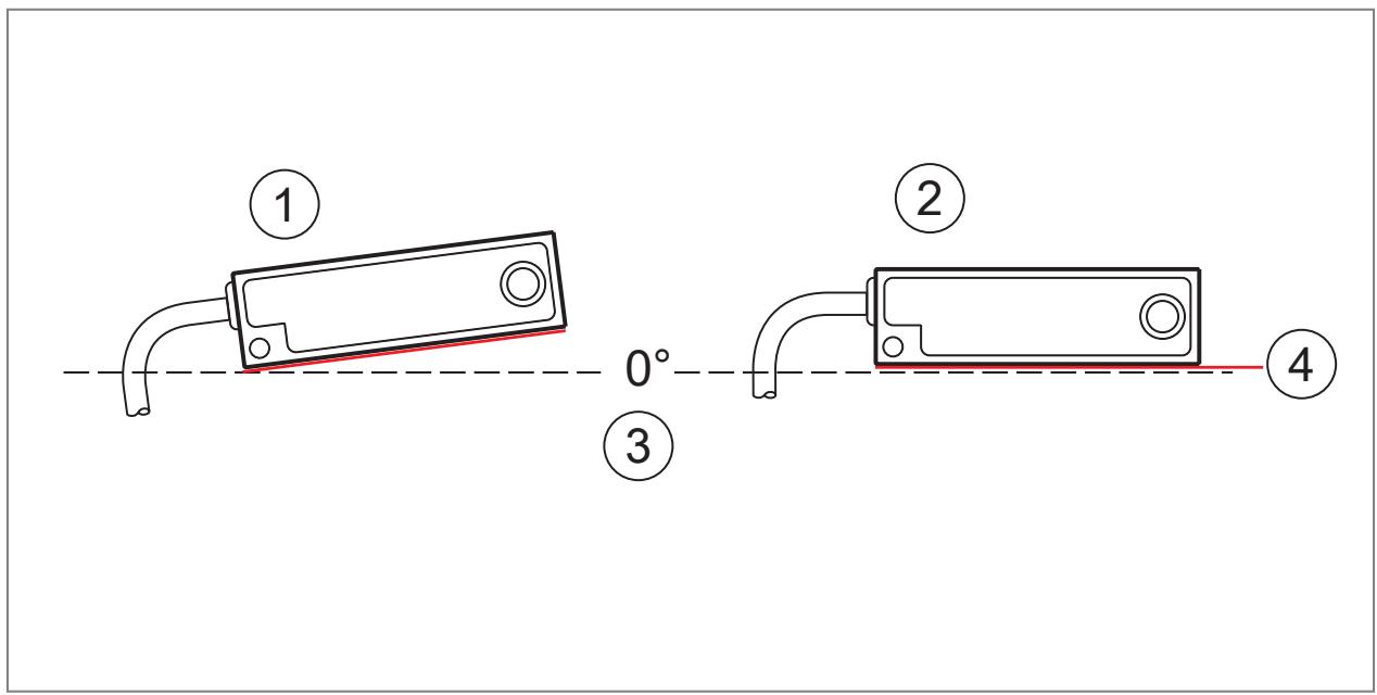
1: Position "OFF" → Contact open
2: Position "ON" → Contact closed
3: Horizontal plane (absolute zero)
4: Reference level
Note on switch point SP
- Setpoint: In horizontal installation position (+/-1°) by rotating the reference area (clockwise, from the top to the horizontal plane).
- Reset point: Exceeding the switching hysteresis by rotating the reference area (anti-clockwise, from the horizontal plane upwards).
7.1 Switching characteristics

1: Switching hysteresis reset point "OFF" -2...-5°
2: Switching hysteresis switch point "ON" ±1°
3: Horizontal plane (absolute zero)
8 Maintenance, repair and disposal
The unit is maintenance-free.
▶ Contact ifm in case of malfunction.
▶ Do not open the housing as the unit does not contain any components which can be maintained by the user. The unit must only be repaired by the manufacturer.
▶ Clean the device using a dry cloth.
▶ Dispose of the unit in accordance with the national environmental regulations.
Brand : IFM
Model : EC2061
Category : Tilt sensor