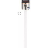
LK7022 - Motion detector IFM - Free user manual and instructions
Find the device manual for free LK7022 IFM in PDF.


User questions about LK7022 IFM
0 question about this device. Answer the ones you know or ask your own.
Ask a new question about this device
Download the instructions for your Motion detector in PDF format for free! Find your manual LK7022 - IFM and take your electronic device back in hand. On this page are published all the documents necessary for the use of your device. LK7022 by IFM.
USER MANUAL LK7022 IFM
Operating instructions
Electronic level sensor
LK10xx
LK70xx
Contents
1 Preliminary note 4
1.1 Symbols used 4
1.2 Warnings.... 4
2 Safety instructions.... 5
3 Intended use.... 6
3.1 Restriction of the application area 6
4 Getting started 7
4.1 Example configuration 1 7
4.2 Example configuration 2 7
5 Function 9
5.1 Measuring principle.... 9
5.2 Operating principle / features of the device 9
5.2.1 Operating modes 9
5.2.2 Notes on the integrated overflow prevention 10
5.2.3 Display and switching function 10
5.2.4 Offset for indicating the real level in the tank.... 11
5.2.5 Safe state in case of a fault.... 11
5.2.6 IO-Link 11
6 Installation.... 12
6.1 Installation instructions for the operation with overflow prevention 12
6.2 Installation instructions for the operation without overflow prevention 13
6.2.1 Installation in the inactive zone 13
6.2.2 Installation in the active zone A of the probe 14
6.3 Other installation notes 14
6.3.1 Marking of the installation height.... 15
7 Electrical connection.... 16
8 Operating elements and display elements. 17
9 Menu.... 18
9.1 Menu structure 18
Parameter setting 19
10.1 Notes on parameter setting via IO-Link 19
10.2 Parameter setting in general 20
10.3 Basic settings 22
10.3.1 ▶ Determine unit of measurement 22
10.3.2 Setting the offset.... 22
10.3.3 Setting the medium.... 22
10.3.4 Setting the overflow prevention 23
10.3.5 Adjusting the overflow prevention 23
10.4 Setting the output signals 24
10.4.1 Setting the output function.... 24
10.4.2 Setting the switching limits (hysteresis function) 24
10.4.3 Setting the switching limits (window function) 24
10.4.4 Setting the switching delay 24
10.4.5 Setting the switch-off delay 24
10.4.6 Setting the switching logic for the output 24
10.4.7 Defining the response of the outputs in case of a fault (safe state) 25
10.4.8 Configuring the display 25
10.4.9 Resetting all parameters to factory setting 25
10.5 Setting values and calculation aids 25
10.5.1 Setting values [OFS] 25
10.5.2 Setting values [OP] 26
10.5.3 Calculation aids [OP]. 26
10.5.3.1 Definition "from the cover" 27
10.5.3.2 Definition "from the bottom" 27
10.5.4 Setting ranges [SPx] / [FHx] and [rPx] / [FLx] 27
10.6 Application examples 27
10.6.1 Hydraulic power unit 27
10.6.2 Pumping station 28
10.6.3 Storage tank / hydraulic unit 29
11 Operation 31
11.1 Operating indicators 31
11.2 Reading the set parameters 31
11.3 Error indications 31
11.4 Output response in different operating states 32
12 Repair, maintenance and disposal 33
12.1 Maintenance information for the operation without overflow prevention 33
13 Factory setting 34
1 Preliminary note
You will find instructions, technical data, approvals and further information using the QR code on the unit / packaging or at documentation.ifm.com.
1.1 Symbols used
√ Requirement
Instructions
Reaction, result
[...] Designation of keys, buttons or indications
→ Cross-reference

Important note
Non-compliance may result in malfunction or interference.

Information
Supplementary note
1.2 Warnings
Warnings indicate the possibility of personal injury and damage to property. This enables safe product handling. Warnings are graded as follows:

WARNING
Warning of serious personal injury
▷ If the warning is not observed, fatal and serious injuries are possible.

CAUTION
Warning of minor to moderate personal injury
▷ If the warning is not observed, minor to moderate injuries are possible.
ATTENTION
Warning of damage to property
▷ If the warning is not observed, damage to property is possible.
2 Safety instructions
- The unit described is a subcomponent for integration into a system.
- The system architect is responsible for the safety of the system.
-
The system architect undertakes to perform a risk assessment and to create documentation in accordance with legal and normative requirements to be provided to the operator and user of the system. This documentation must contain all necessary information and safety instructions for the operator, the user and, if applicable, for any service personnel authorised by the architect of the system.
-
Read this document before setting up the product and keep it during the entire service life.
- The product must be suitable for the corresponding applications and environmental conditions without any restrictions.
- Only use the product for its intended purpose (→ Intended use).
- If the operating instructions or the technical data are not adhered to, personal injury and/or damage to property may occur.
- The manufacturer assumes no liability or warranty for any consequences caused by tampering with the product or incorrect use by the operator.
- Installation, electrical connection, set-up, operation and maintenance of the product must be carried out by qualified personnel authorised by the machine operator.
- Protect units and cables against damage.
- Only use the product for permissible media (→ Technical data).
- The unit complies with the standard EN 61000-6-4 and is a class A product. The unit may cause radio interference in domestic areas. If interference occurs, the user must take appropriate actions.
3 Intended use
The device was especially designed to meet the requirements of machine tool building. It is particularly suitable for monitoring coolant emulsions (also dirty) as well as cutting and hydraulic oils.
3.1 Restriction of the application area
• The device is not suitable for:
- acids and alkalis
– hygienic and electroplating applications
– highly conductive and adhesive media (e.g. glue, shampoo),
– granulates, bulk material,
– use in grinders (increased risk of formation of deposits).
- It is possible that foam of good conductivity is detected as level:
▶ Check the correct function by performing an application test.
- For water-based media with temperatures > 35 °C, install the device in a climatic tube (→ Accessories).
- Observe max. media temperature with climatic tube: → Technical data sheet.
- For automatic medium detection: for media which are very inhomogeneous, separate from each other thus forming separation layers (e.g. oil layer on water) the following applies:
▶ Check the correct function by performing an application test.
4 Getting started
For fast set-up, the example configurations described in the following can be used for most applications. The indicated minimum distances apply exclusively to each separately described case.
4.1 Example configuration 1
| Device: | LK1022 (probe length L= 264 mm) |
| Medium to be detected: | Mineral oil |
| Operating mode: | Manual media selection with overflow prevention (factory setting Lk10xx): Operating modes (→ ☐ 9) |
| Installation environment: | Installation as in → Figure Metal tank |

Fig. 1: Example configuration 1 metal tank
▶ Install device.
▶ Observe the distances (x), (u) and (c):
| x: | min. 4.0 cm |
| u: | min. 1.0 cm |
| c: | max. 14.0 cm |
▶ Ground sensor and tank: Electrical connection ( → ☐ 16)
▶ Observe the parameter setting sequence:
• [MEdl] = [OIL.2]: Setting the medium ( → ☐ 22)
- [OFS] = (u); e. g. (u) = 2.0 cm: Offset for indicating the real level in the tank (→ ☐ 11)
- [OP]: Set the overflow prevention OP at a distance (y) greater than 4.5 cm below the mounting element.
For distances (y) smaller than 4.5 cm there may be malfunctioning and error messages during the adjustment process [cOP]
Step increment and setting range: Setting values [OP] (→ 26)
Calculation aids for [OP]: Calculation aids [OP] ( → ☐ 26)
▶ Adjust overflow prevention OP to [cOP]: Adjusting the overflow prevention ( → ☐ 23)
▷ The device is ready for operation.
▶ Make further settings if necessary.
▶ Check whether the device operates correctly.
4.2 Example configuration 2
| Device: | LK7023 (with factory setting); probe length L = 472 mm |
| Medium to be detected: | Coolant emulsion |
| Operating mode: | Automatic medium detection (factory setting LK70xx): Operating modes (→ ☐ 9) |
| Installation environment: | Installation as in → Figure Metal tank |

Fig. 2: Example configuration 2 metal tank
▶ Install device.
▶ Observe the distances (x), (u) and (c):
| x: | min. 4.0 cm |
| u: | min. 1.0 cm |
| c: | max. 23.0 cm |
▶ Ground sensor and tank: Electrical connection ( → 16)
▶ Observe the maximum permitted level (b).
A distance (a2) greater than 5.0 cm has to be observed between maximum level (b) and mounting element.
▶ Observe the parameter setting sequence:
• [MEdl] = [Auto]: Setting the medium ( → ☐ 22)
- [OFS] = (u), e.g. (u) = 1.0 cm: Offset for indicating the real level in the tank (→ ☐ 11)
- [SP1] = Set the switch point at a distance (a2) greater than 5.0 cm below the mounting element.
Adjustable in step increments of 0.5 cm. Switch point [SP1] is used as overflow prevention (pump off, close inlet).
▶ The device must be reinitialised:
▶ Switch the operating voltage off and on again.
▷ The device is ready for operation.
▶ Make further settings if necessary.
▶ Check whether the device operates correctly.
5 Function
5.1 Measuring principle
The sensor determines the level according to the capacitive measuring principle.
- An electrical field [E] is generated and influenced by the medium to be detected. This change to the field causes a measurement signal that is electronically evaluated.
- The dielectric constant of a medium is important for its detection. Media with a high dielectric constant (e.g. water) generate a strong measurement signal, media with a low dielectric constant (e.g. oils) a correspondingly lower signal.
- The active measuring range of the sensor probe has 16 capacitive measuring segments. They generate measurement signals depending on the degree of coverage.
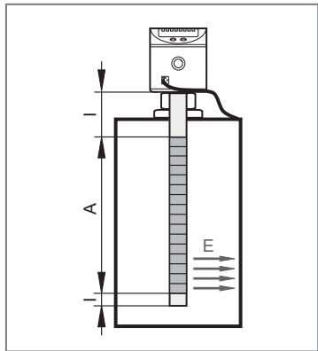
Fig. 3: Measuring principle
I: Inactive zone
A: Active zone (16 active segments)
E: Electrical field
Dimensions → Technical data sheet
5.2 Operating principle / features of the device
The device can be installed in tanks of different sizes and mounted flexibly.
2 outputs are available. They can be set separately.
| OUT1 | Switching signal for level limit value / IO-Link |
| OUT2 | Switching signal for level limit value |
▶ To adjust to the present application select the required operating mode.
5.2.1 Operating modes
- Manual media selection with overflow prevention (factory setting LK10xx) recommended! Highest operational reliability!
The medium to be detected is set manually (Parameter [MEdI]). In addition, an integrated, independently functioning overflow prevention is available.
- Manual media selection without overflow prevention. Medium operational reliability!
The medium to be detected is set manually as described under 1. However, the overflow prevention is deactivated (Parameter [OP] = [OFF]). For this reason, no adjustment is required.
- Automatic medium detection (factory setting LK70xx). Lowest operational reliability!
Each time the operating voltage is switched on, the device adjusts itself to the medium and the installation environment.
For automatic media detection (Parameter [MEdI] = [Auto]), no overflow prevention is available! Automatic media detection can only function properly under certain conditions (e.g. compliance with special mounting specifications, restrictions for operation and maintenance): Maintenance information for the operation without overflow prevention ( → ☐ 33)
5.2.2 Notes on the integrated overflow prevention
With the parameter [OP] (OP = overflow prevention), one of the upper measuring segments is defined as integrated overflow prevention OP.
- If the overflow prevention OP is activated, an adjustment to the installation situation has to be made (Parameter [cOP]). Otherwise, the device is not ready for operation; [ ] is indicated in the display: Operating indicators (→ 31)
• The overflow prevention OP can be deactivated ([OP] = [OFF]).
Deactivating the overflow prevention OP can impair the operational reliability. For optimum operation and maximum operational reliability, we therefore recommend not to deactivate the overflow prevention OP!
- The overflow prevention OP is the maximum limit of the measuring range. The switch points [SPx] / [FHx] are always below [OP].
- The overflow prevention OP is not assigned to a separate output. It offers additional protection and only switches if, as the level rises, one of the outputs has not switched even though the corresponding switch point has been exceeded (e.g. due to application-related malfunctions). The response of the overflow prevention OP thus triggers the “full state” according to the configured switching functions: Display and switching function ( → ☐ 10)
- Typically the overflow prevention OP reacts when the selected measuring segment has been reached (a few mm before the set OP value).
- The overflow prevention OP reacts immediately and without delay. The set delay times (e.g. of a switch point directly below) have no effect on the overflow prevention OP.
- The response of the overflow prevention OP is indicated on the display (Full and indication of the current level change every second).
5.2.3 Display and switching function
The device displays the current level, selectable in cm or inches. The display unit is defined by parameter setting. The set unit of measurement and the switching status of the outputs are indicated by LEDs.
The device signals via two switching outputs (OUT1/OUT2) that a set limit has been exceeded or that the level is below the limit. The parameters of the switching outputs can be set:
- Hysteresis function / normally open → Figure Hysteresis function: [oux] = [Hno].
- Hysteresis function / normally closed → Figure Window function: [oux] = [Hnc].
First the setpoint [SPx] is set, then the reset point [rPx] with the requested difference.
The hysteresis for the overflow prevention OP is fixed.
- Window function / normally open → Figure Hysteresis function: [oux] = [Fno].
- Window function / normally closed → Figure Window function: [oux] = [Fnc].
The width of the window can be set by means of the difference between [FHx] and [FLx]. [FHx] = upper value, [FLx] = lower value.
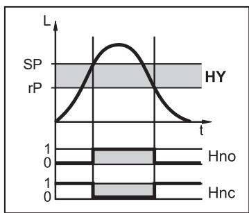
Fig. 4: Hysteresis function
L: level
HY: hysteresis
FE: window

Fig. 5: Window function
L: level
HY: hysteresis
FE: window
5.2.4 Offset for indicating the real level in the tank
The zone between tank bottom and lower edge of the probe can be entered as offset value [OFS]. So display and switch points refer to the actual level (point of reference = tank bottom).

For [OFS] = [0]: The reference point is the lower edge of the measuring probe.

The set offset only refers to the display on the device. It has no effect on the process value transmitted via IO-Link. The OFS parameter, however, is correctly transmitted via IO-Link and can therefore be taken into account: IO-Link ( → ☐ 11)
5.2.5 Safe state in case of a fault
For each output, a safe state in the event of a fault can be set. If a fault is detected, the outputs immediately pass into the defined, safe state. For this case the response of the outputs can be set via the parameters [FOU1], [FOU2]: Defining the response of the outputs in case of a fault (safe state) ( → ☐ 25)
5.2.6 IO-Link
IO-Link is a communication system for connecting intelligent sensors and actuators to automation systems. IO-Link is standardised in the IEC 61131-9 standard.

General information on IO-Link at io-link.ifm

Input Output Device Description (IODD) with all parameters, process data and detailed descriptions of the device at documentation.ifm.com
IO-Link offers the following advantages:
• Interference-free transmission of all data and process values
• Parameter setting in the running process or presetting outside the application
- Parameters for identifying the connected devices in the system
• Additional parameters and diagnostic functions
• Automatic backup and restore of parameter sets in case of device replacement (data storage)
- Logging of parameter sets, process values and events
• Device description file (IODD - Input Output Device Description) for easy project planning
• Standardised electrical connection
- Remote maintenance
6 Installation

Fig. 6: Installation
| L: | Probe length | u...y: | Minimum distances |
| M: | Zone for mounting element | OP: | Overflow prevention |
| c: | Maximum outside length | B: | Metallic objects in the tank |
Table installation:
| LKx022 | LKx023 | LKx024 | ||||
| [cm] | [inch] | [cm] | [inch] | [cm] | [inch] | |
| L (probe length) | 26.4 | 10.4 | 47.2 | 18.6 | 72.8 | 28.7 |
| M (mounting zone) | 14.0 | 5.5 | 23.0 | 9.1 | 36.0 | 14.2 |
| c (max. outside length)* | ||||||
* Applies to installation as shown (wall thickness of the tank lid not taken into account; mounting element does not protrude into the tank). Otherwise note mounting zone M.
6.1 Installation instructions for the operation with overflow prevention
[MEdI] = [CLW..] or [OIL..]
[OP] = [Value ...] ( Overflow prevention OP activated )

It is permitted to fix mounting elements within the mounting zone (M) → Figure Installation.
▶ Adhere to the maximum permitted outside length (c) according to the → Table Installation.
▶ Observe the minimum distances according to → Figure Mounting and → Table Mounting instructions for operation with overflow prevention.
▶ Observe the notes on the integrated overflow prevention OP.

The overflow prevention OP must:
-
be below the mounting element
-
be set at a minimum distance (y) to it. The minimum distance is measured between the lower edge of the mounting element and the OP value.
Table installation instructions for the operation with overflow prevention:
| MEdI = CLW.1 | MEdI = CLW.2, OIL.1 | MEdI = OIL.2 | ||||
| [cm] | [inch] | [cm] | [inch] | [cm] | [inch] | |
| x | 2.0 | 0.8 | 3.0 | 1.2 | 4.0 | 1.6 |
| u | 1.0 | 0.4 | 1.0 | 0.4 | 1.0 | 0.4 |
| MEdl = CLW.1 | MEdl = CLW.2, OIL.1 | MEdl = OIL.2 | ||||
| y (LKx022) | 2.5 | 1.0 | 3.5 | 1.4 | 4.5 | 1.8 |
| y (LKx023) | 4.5 | 1.8 | 5.5 | 2.2 | 6.5 | 2.6 |
| y (LKx024) | 6.0 | 2.4 | 7.0 | 2.8 | 8.0 | 3.2 |
| v | 4.5 | 1.8 | 4.5 | 1.8 | 4.5 | 1.8 |
| w | 4.0 | 1.6 | 5.0 | 2.0 | 6.0 | 2.4 |

Calculation aids for [OP]: Calculation aids [OP] (→ 26)
6.2 Installation instructions for the operation without overflow prevention
[MEdl] = [Auto] or [OP] = [OFF] (overflow prevention OP deactivated)
6.2.1 Installation in the inactive zone
Between the maximum level (b1) and the inactive zone (l1), the minimum distance (a1) has to be adhered to. → Figure and → Table Mounting in the inactive zone.
▶ Fix the device using mounting elements in the inactive zone (I1). The outside length (c) must not exceed (I1).
▶ Ensure that the maximum level (b1) is not exceeded after completed installation.
▶ Observe further minimum distances. → Table Installation in the active zone A of the probe.

Fig. 7: Installation in the inactive zone
I1 / I2: Inactive zones
A: Active zone
a1: Minimum distance between the inactive zone (I1) and the maximum level (b1)
b1: Max. level from the lower edge of the sensor (without offset)
c: Outside length (maximum outside length → Table Installation)
Table installation in the inactive zone:
| LKx022 | LKx023 | LKx024 | ||||
| [cm] | [inch] | [cm] | [inch] | [cm] | [inch] | |
| I1 | 5.3 | 2.1 | 6.0 | 2.4 | 10.4 | 4.1 |
| A | 19.5 | 7.7 | 39.0 | 15.4 | 58.5 | 23.0 |
| a1 | 1.0 | 0.4 | 1.5 | 0.6 | 2.5 | 1 |
| b1 | 20.0 | 7.9 | 39.5 | 15.6 | 59.5 | 23.4 |
6.2.2 Installation in the active zone A of the probe
Between the maximum level (b2) and the mounting element a minimum distance (a2) has to be observed. → Figure and → Table Installation in the active zone A of the probe.
▶ Fix mounting elements in the mounting zone (M) → Figure Installation. Adhere to the maximum permitted outside length (c). → Table Installation.
▶ Ensure that the maximum level (b2) is not exceeded after completed installation:
▶ (b2) = (L) - (c) - (a2) (without offset).
▶ Observe further minimum distances. → Table Installation in the active zone A of the probe.
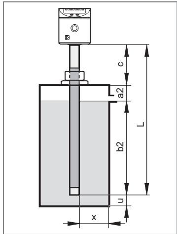
Fig. 8: Installation in the active zone A of the probe
c: Outside length (maximum outside length → Table Installation)
a2: Minimum distance between mounting element and maximum level (b2).
b2: Max. level from the lower edge of the sensor
Table installation in the active zone A of the probe:
| LKx022 | LKx023 | LKx024 | ||||
| [cm] | [inch] | [cm] | [inch] | [cm] | [inch] | |
| x | 2.0 | 0.8 | 3.0 | 1.2 | 4.0 | 1.6 |
| u | 1.0 | 0.4 | 1.0 | 0.4 | 1.0 | 0.4 |
| a2 (LKx022) | 2.0 | 0.8 | 2.5 | 1.0 | 3.0 | 1.2 |
| a2 (LKx023) | 4.0 | 1.6 | 4.5 | 1.8 | 5.0 | 2.0 |
| a2 (LKx024) | 6.0 | 2.4 | 7.0 | 2.8 | 8.0 | 3.2 |
| v*) | 4.5 | 1.8 | 4.5 | 1.8 | 4.5 | 1.8 |
| w*) | 4.0 | 1.6 | 5.0 | 2.0 | 6.0 | 2.4 |
*) → Figure Installation: Installation (→ 12)
In case of automatic medium detection [MEdl] = [Auto] or deactivated overflow prevention [OP] = [OFF], the sensor reinitialises itself each time it is switched on and makes adjustments to the medium and the installation environment. The active zone / measuring range must not be completely covered by the medium. The indicated minimum distances ensure this. Too short a distance may lead to maladjustments and malfunctions.
6.3 Other installation notes
- For mounting in plastic pipes / plastic tanks, the inside (pipe) diameter must at least be 12.0 cm (4.8 inches).
▶ Install the sensor in the centre. - For mounting in metal pipes the inside pipe diameter (d) must be at least:
Table other installation instructions:
| MEdI = CLW.1 | MEdI = CLW.2, OIL.1 | MEdI = OIL.2/ Auto | ||||
| [cm] | [inch] | [cm] | [inch] | [cm] | [inch] | |
| d | 4.0 | 1.6 | 6.0 | 2.4 | 10.0 | 4.0 |
6.3.1 Marking of the installation height
▶ Fix the set installation height with the supplied stainless steel tube clip.
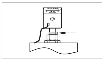
If the sensor is removed from the fixture for maintenance reasons, the clip serves as a limit stop when remounting the sensor. Thus an inadvertent maladjustment of the sensor is excluded. This is in particular necessary for the correct function of the overflow prevention OP.
Fig. 9: Marking of the installation height
▶ Fit the stainless steel tube clip using pliers.
▶ Ensure a safe fit.
▶ To remove the clip it has to be destroyed.
7 Electrical connection

The unit must be connected by a qualified electrician.
Observe the national and international regulations for the installation of electrical equipment.
Voltage supply according to SELV, PELV.
▶ Disconnect power.
▶ Connect the unit as follows:


| Pin | Core colour | |
| 1: | BN | Brown |
| 2: | WH | White |
| 3: | BU | Blue |
| 4: | BK | Black |
| OUT1: switching output / IO-Link | ||
| OUT2: switching output | ||
| Colours to DIN EN 60947-5-2 | ||

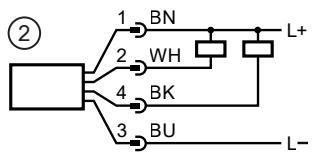
Fig. 10: Circuit examples
1: 2 x pnp
2: 2 x npn


For safe function, the sensor housing must be electrically connected to the counter-electrode / grounded (= functional earth).
Use the housing connection (see drawing) and a short piece of cable with a wire cross-section of at least 1.5 mm2 .
When using metal tanks, the tank wall serves as the counter-electrode.
For plastic tanks, a counter-electrode must be provided, e.g. a metal rod / metal plate inside the tank in parallel with the probe. Observe the minimum distances to the probe.
8 Operating elements and display elements
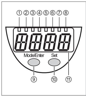
| 1 to 8: Indicator LEDs | |
| LED 1 | Indication in centimetres |
| LED 2 | Indication in inches |
| LED 3 - 6 | Not used. |
| LED 7 | Switching status OUT2 (on if output 2 is switched). |
| LED 8 | Switching status OUT1 (on if output 1 is switched). |
| 9: [Mode/Enter] button | |
| • Selection of the parameters and acknowledgement of the parameter values. | |
| 10: [Set] button | |
| • Setting of the parameter values (scrolling by holding pressed, incrementally by pressing once). | |
| 11: Alphanumeric display, 4 digits | |
| • Display of the current level.• Indication of the parameters and parameter values.• Display of the operating and fault indication. | |
9 Menu
9.1 Menu structure
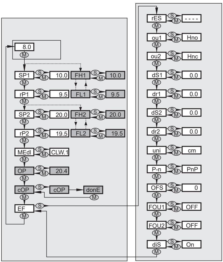

Menu items highlighted in grey, e.g. [cOP], are only active when assigned parameters have been selected.
10 Parameter setting

Depending on the parameter setting, the parameters available in the menu may change.
Parameter setting can be carried out via the IO-Link interface or via the operating elements on the unit.
Parameters can be set before installation or during operation.

If you change parameters during operation, this will influence the function of the plant.
▶ Ensure that there will be no malfunctions in your plant.
During parameter setting the unit remains in the operating mode. It continues to monitor with the existing parameter until the parameter setting has been completed.

To adjust the overflow prevention [cOP], the device must be installed in the tank.
Requirements for parameter setting via the IO-Link interface:
√ A suitable parameter setting software, e.g. ifm moneo|configure
√ The Input Output Device Description (IODD) for the device, see documentation.ifm.com
√ One IO-Link master
▶ Connect the IO-Link master to a parameter setting software.
▶ Set the port of the master to the IO-Link operating mode.
▶ Connect the device to a free port of the IO-Link master.
▷ The unit switches to IO-Link mode.
▶ Change parameter settings in the software.
▶ Write parameter settings to the unit.

Notes on parameter setting → Manual of the parameter setting software
10.1 Notes on parameter setting via IO-Link

▶ On delivery the device LKxxxx is not operational.
▶ First, the integrated overflow prevention [OP] has to be adjusted.
▶ Depending on the application, [OP] adjustment can be carried out in different ways:
• directly on the display.
- via an IO-Link tool, button "Teach_OP [cOP]".
• via the controller: write the value 208 to the IO-Link index 2 (length: 1 byte).

The OP adjustment is not part of the data storage.
Therefore, a simple replacement (e.g. in case of a device failure) (provided the OP is not deactivated: Operating modes ( → ☐ 9)) is only possible with reservations: on the new device, the OP adjustment has to be carried out manually, either via the operating keys or via IO-Link. Only when the OP adjustment has been carried out successfully does the device revert to the cyclical process data transmission.

After a factory reset (button "Restore Factory Settings"), the device reboots and the factory settings are restored.
10.2 Parameter setting in general
3 steps must be taken for each parameter setting:
1: Select Parameter
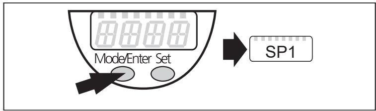
▶ Press [Mode/Enter] until the requested parameter is displayed.
2: Set parameter value
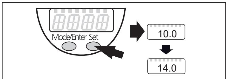
▶ Press [SET] and keep it pressed.
▷ Current setting value of the parameter flashes for 5 s.
▷ After 5 s: the setting value is changed. Incrementally by pressing the button once or continuously by keeping the button pressed.
▷ The numerical values are incremented continuously:
For reducing the value:
▶ Let the display move to the maximum setting value. Then the cycle starts again at the minimum setting value.
3: Acknowledge parameter value

▶ Briefly press [Mode/Enter].
▷ The parameter is displayed again. The new setting value is saved.
Setting of other parameters:
▶ Start again with step 1.
Finishing the parameter setting:
▶ Press [Mode/Enter] several times until the current measured value is displayed, or wait for 30 s.
▷ The sensor returns to the process value display.
If [C. Loc] is displayed when an attempt is made to modify a parameter value, a parameter setting process is active via the IO-Link communication (temporary locking).

If [S. Loc] is displayed, the sensor is permanently locked via software. This locking can only be removed with a parameter setting software.
Change from menu level 1 to menu level 2
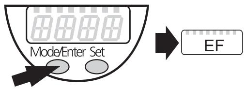
▶ Press [Mode/Enter] until [EF] is displayed.
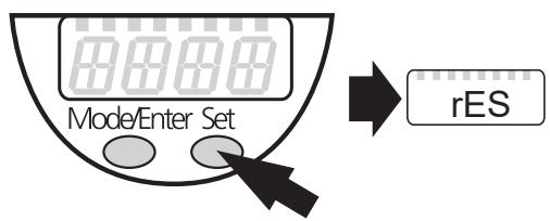
▶ Briefly press [Set].
▷ The first parameter of the submenu is displayed (here: [rES]).
Lock / unlock
The device can be locked electronically to prevent unintentional settings.
Locking:

▶ Make sure that the device is in normal operating mode.
▶ Press [Mode/Enter] + [Set] simultaneously for 10 s.
▷ [Loc] is displayed.
[Loc] is briefly displayed if you try to change parameter values.
Unlocking:

▶ Press [Mode/Enter] + [Set] simultaneously for 10 s.
▷ [uLoc] is displayed.
Timeout:
If no button is pressed for 30 s during parameter setting, the device returns to the operating mode with unchanged values.

The device can be configured before or after installation.
Exception: to adjust the overflow prevention [cOP], the device must be installed in the tank.
10.3 Basic settings
Setting ranges of all parameters: Setting values and calculation aids ( → ☐ 25)
Factory settings of all parameters: Factory setting ( → ☐ 34)
10.3.1 Determine unit of measurement

▶ Enter [uni] before entering the values for SPx, rPx, OP or OFS.
▷ This avoids unintentional wrong settings.
| ▶ Select [uni]▶ Determine unit of measurement: [cm], [inch] | [uni] |
10.3.2 Setting the offset
The distance between tank bottom and lower edge of the measuring probe can be entered as offset value.

▶ Set [OFS] before entering the values for SPx, rPx or OP.
▷ This avoids unintentional wrong settings.
| ▶ Select [OFS]. ▶ Set the value for the offset. Note the set unit of measurement [uni]. | [OFS] |
10.3.3 Setting the medium
| ▶ Select [MEdL]. | [MEdl] | |
| [CLW.1] = | Water, water-based media, coolant emulsions. | |
| [CLW.2] = | Water, water-based media, coolant emulsions for temperatures > 35 °C (installation in climatic tube). | |
| [OIL.1] = | Oils with an increased dielectric constant (e.g. some synthetic oils). | |
| [OIL.2] = | Oils with a low dielectric constant (e.g. mineral oils). | |
| [Auto] = | Automatic medium detection: Operating modes (→ ☐ 9) | |
▶ In case of doubt, select [OIL.2] for oils.
▶ Check the correct function by performing an application test.

The settings [CLW.1] and [CLW.2] suppress deposits (e.g. metal swarf).
The settings [OIL.1] and [OIL.2] suppress a bottom layer of higher dielectric water or swarf which is a few cm high. If no oil layer is present (or if it is very thin), the bottom layer is detected.
With the setting [MEdl] = [Auto], no overflow prevention OP is available. In that case, the menu items [OP] and [cOP] are not available.
10.3.4 Setting the overflow prevention
| ▶ Observe minimum distances and installation specifications▶ Select [OP]▶ Define the position of the overflow prevention OP. The option [OP] = [OFF]deactivatesthe overflow prevention OP. | [OP] |

▶ Set [OP] before [SPx] or [FHx].
▷ If [OP] is reduced after setting [SPx] / [FHx] to a value ≤ [SPx] / [FHx], [SPx] / [FHx] shifts downwards.
▷ If [OP] is increased, [SPx] / [FHx] is also increased if [OP] and [SPx] / [FHx] are close together (1 x step increment).

When the overflow prevention is deactivated [OP] = [OFF] or [MEdI] = [Auto], the safe function of the sensor must be verified with particular care. Switch-on and switch-off processes and special operating states such as very full tanks, possible maintenance and cleaning operations are to be considered in the verification.

▶ For the setting [OP] = [OFF], the menu item [cOP] is not available.
10.3.5 Adjusting the overflow prevention

Only adjust the overflow prevention OP when the device is installed. If possible, carry out the adjustment when the tank is empty.
The tank may be partly filled.
▶ Make sure that the overflow prevention OP is not covered by the medium. Observe the minimum distance between the overflow prevention OP and the level.
| ▶ Select [cOP] | [cOP] |
| ▶ Press [Set] and keep it pressed. | |
| ▷ [cOP] flashes for some seconds; then the continuous display indicates that the adjustment is being made. | |
| ▷ If the adjustment is successful, [donE] is displayed. | |
| ▶ Confirm by clicking on [Mode/Enter]. | |
| ▷ If the adjustment is not successful, [FAIL] is displayed. | |
| ▶ If necessary, lower the level or correct the position of the overflow prevention [OP] and repeat the adjustment operation. |
Table minimum distance between the overflow prevention OP and the level during adjustment:
| [cm] | [inch] | |
| LKx022 | 2.0 | 0.8 |
| LKx023 | 3.5 | 1.4 |
| LKx024 | 5.0 | 2.0 |

The position of the overflow prevention OP can be determined by calling up the parameter [OP]. Note the offset if necessary.
The current level is to be determined manually since the device is not yet ready for operation before the adjustment.

When the overflow prevention is activated ([OP] = [value ...]), an adjustment [cOP] must be carried out each time:
- [MEdl] or [OP] have been changed. In this case is displayed.
- the installation position (height, orientation) was changed.
- the connection between the sensor and the tank ground (e.g. cable length) was changed.
With deactivated overflow prevention ([OP] = [OFF] or [MEdI] = [Auto]):
To apply the basic settings and to adapt to the medium and installation environment the device has to be reinitialised when installed.
▶ Switch the operating voltage off and on again.
10.4 Setting the output signals
10.4.1 Setting the output function
| ▶ Select [OU1] / [OU2] and set the switching function:• [Hno] = hysteresis function/normally open• [Hnc] = hysteresis function/normally closed• [Fno] = window function/normally open• [Fnc] = window function/normally closed Note: if the switch point is used as an overflow prevention, the setting [OUx] = [Hnc] (NC function) is recommended. The principle of normally closed operation ensures that wire break or cable break is also detected. | [OU1][OU2] |
10.4.2 Setting the switching limits (hysteresis function)
| ▶ Make sure that the function [Hno] or [Hnc] is set for [OU1] or [OU2]. ▶ Select [SP1] / [SP2] and set the value at which the output switches. | [SP1][SP2] |
| ▶ Select [rP1] / [rP2] and set the value at which the output switches off. [rPx] is always smaller than [SPx]. The device only accepts values which are lower than the value for [SPx]. If [SPx] is shifted, [rPx] also shifts provided that the lower end of the setting range is not reached. | [rP1][rP2] |
10.4.3 Setting the switching limits (window function)
| ▶ Make sure that the function [Fno] or [Fnc] is set for [OU1] or [OU2]. ▶ Select [FH1] / [FH2] and set the upper limit of the acceptable range. | [FH1][FH2] |
| ▶ Select [FL1] / [FL2] and set the lower limit of the acceptable range. [FLx] is always smaller than [FHx]. The device only accepts values which are lower than the value for [FHx]. If [FHx] is shifted, [FLx] also shifts provided that the lower end of the setting range is not reached. | [FL1][FL2] |
10.4.4 Setting the switching delay
| ▶ Select [dS1] / [dS2] and set the value between 0.0 and 60 s. The switching delay reacts according to VDMA. | [dS1][dS2] |
10.4.5 Setting the switch-off delay
| ▶ Select [dr1] / [dr2] and set the value between 0.0 and 60 s. The switch-off delay reacts according to VDMA. | [dr1][dr2] |
10.4.6 Setting the switching logic for the output
| ▶ Select [P-n] and set [PnP] or [nPn]. | [P-n] |
10.4.7 Defining the response of the outputs in case of a fault (safe state)
| ▶ Select [FOUx] and set the value:• [On] = switching output switches ON in case of a fault.• [OFF] = switching output switches OFF in case of a fault. Hardware faults (error message [Err]) or a faulty data set (error message [PArA]) are considered to be faults: Error indications (→ 31)Overflow or activation of the overflow prevention OP is not considered to be a fault. | [FOU1][FOU2] |
10.4.8 Configuring the display
| ▶ Select [dis] and set the value:[on] = the display is switched on in the operating mode. Update of the measured values every 500 ms [OFF] = the display is switched off in the operating mode. When one of the buttons is pressed, the current measured value is displayed for 30 s. The indicator LEDs remain active even if the display is deactivated. | [diS] |
10.4.9 Resetting all parameters to factory setting
| ▶ Select [rES]▶ Press and hold [Set] until [----] is displayed. ▶ Briefly press [Mode/Enter]. ▷ The device reboots and then the factory settings are restored. | [rES] |
10.5 Setting values and calculation aids
10.5.1 Setting values [OFS]
| [cm] | [inch] | |||
| Setting range | 0...200.0 | 0...78.8 | ||
| LKx022 LKx023 | LKx024 | LKx022 LKx023 | LKx024 | |
| Step increment | 0.5 | 1 | 0.2 | 0.5 |
10.5.2 Setting values [OP]
![IFM LK7022 - Setting values [OP] - 1](/content/2026/04/596669/images/a2092095f7ed9cb243d5ac7956e1f2080fa45a0e430153807cfcae4649b544d7.jpg)
Fig. 11: Setting values / OPx: Setting range [OP]
| Section | LKx022 | LKx023 | LKx024 | |||
| [cm] | [inch] | [cm] | [inch] | [cm] | [inch] | |
| 1 | 20.4 | 8.0 | 40.7 | 16.0 | 61 | 23.9 |
| 19.1 | 7.5 | 38.3 | 15.1 | 57 | 22.4 | |
| 17.9 | 7.1 | 35.8 | 14.1 | 53 | 21.0 | |
| 16.7 | 6.6 | 33.4 | 13.1 | 50 | 19.5 | |
| 15.5 | 6.1 | 31.0 | 12.2 | 46 | 18.1 | |
| 14.3 | 5.6 | 28.5 | 11.2 | 42 | 16.7 | |
| 13.0 | 5.1 | 26.1 | 10.3 | 39 | 15.2 | |
| 11.8 | 4.7 | 23.6 | 9.3 | 35 | 13.8 | |
| 10.6 | 4.2 | 21.2 | 8.3 | 31 | 12.3 | |
| 9.4 | 3.7 | 18.8 | 7.4 | 28 | 10.9 | |
| 8.2 | 3.2 | 16.3 | 6.4 | 24 | 9.5 | |
| 2 | 6.9 | 2.7 | 13.9 | 5.5 | 20 | 8.0 |
![IFM LK7022 - Setting values [OP] - 2](/content/2026/04/596669/images/f71b3aca35921df63548fbd4e83476323a84f5844a53ea74ada3abed11ac4ab0.jpg)
The indicated values for [OP] refer to the distance between OP and the lower edge of the probe. The values apply if [OFS] = [0] .
If [OFS] > [0], they increase by the set offset value.
Example LK1022:
According to → Table Setting values [OP], OP has to be set to segment 20.4 cm.
[OFS] = 7. 0 cm
[OP] is to be set to 20.4 cm + 7.0 cm = 27.4 cm.
10.5.3 Calculation aids [OP]
![IFM LK7022 - Calculation aids [OP] - 1](/content/2026/04/596669/images/07d5e61cf382c49d07839399a4826b0c613584c52aeb0d3c3f1e0223b527bfe1.jpg)
For proper functioning of the overflow prevention OP the minimum distance (y) ( → Figure: definition from above) must be observed.
The following correlations apply:
| B + c = L + uandB = z + y | B: Tank heightc: Outside length (maximum: Installation(→ □ 12)).y: Required response level OP from above (minimum: Installation instructions for the operation with overflow prevention(→ □ 12), maximum: Setting values [OP](→ □ 26). | L: Probe lengthu: Distance between probe and tank bottomz: Required response level OP from the bottom (max-imum: z < L - c - y or z < B - y) |
10.5.3.1 Definition "from the cover"
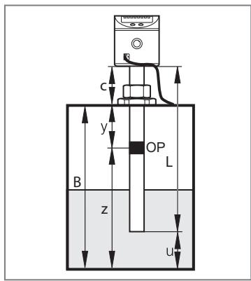
Fig. 12: Definition "from the cover"
Required distance (y) of the overflow prevention OP "from the cover" is defined.
• Without offset ([OFS] = [0]): [OP] = L - c - y
- With offset ([OFS] = u): [OP] = L - c - y + u or
[OP] = B - y
Example:
c = 3. 0 cm, y = 5. 0 cm, u = 1. 0 cm
Without offset: [OP] = 26.4 cm - 3.0 cm - 5.0 cm = 18.4 cm
With offset: [OP] = 26.4 cm - 3.0 cm - 5.0 cm + 1.0 cm = 19.4 cm
10.5.3.2 Definition "from the bottom"
Response level (z) of the overflow prevention OP from the tank bottom is defined.
• Without offset ([OFS] = [0]): [OP] = z - u
• With offset ([OFS] = u): [OP] = z
Example:
z = 18.0 cm (from the tank bottom), u = 1.0 cm
Without offset: [OP] = 18.0 cm - 1.0 cm = 17.0 cm
With offset: [OP] = 18.0 cm
▶ Round the calculated value to the next lower adjustable value: Reading the set parameters ( → ☐ 31)
10.5.4 Setting ranges [SPx] / [FHx] and [rPx] / [FLx]
| LKx022 | LKx023 | LKx024 | ||||
| [cm] | [inch] | [cm] | [inch] | [cm] | [inch] | |
| [SPx] / [FHx] | 2.5...20.0 | 1.0...7.8 | 3.5...39.0 | 1.4...15.4 | 6...59 | 2.5...23.5 |
| [rPx] / [FLx] | 2.0...19.5 | 0.8...7.6 | 3.0...38.5 | 1.2...15.2 | 5...58 | 2.0...23.0 |
| Step increment | 0.5 | 0.2 | 0.5 | 0.2 | 1 | 0.5 |
![IFM LK7022 - Setting ranges [SPx] / [FHx] and [rPx] / [FLx] - 1](/content/2026/04/596669/images/273031af3d09277f81213f1995017cc3ad5491ceef77629b20dd0524608c1720.jpg)
The values apply if [OFS] = [0].
If [OFS] > [0], they increase by the set offset value.
10.6 Application examples
10.6.1 Hydraulic power unit
Minimum level monitoring with early warning and alarm
| Switching output 1: early warning | |
| SP1 | slightly above rP1 (to suppress wave movements) |
| rP1 | below preset level → early warning, start refilling |
| ou1 | hysteresis function, normally closed (Hnc) |
| Switching output 2: alarm | |
| SP2 | min. value reached again → Alarm reset |
| rP2 | below min. value → Alarm |
| ou2 | hysteresis function, normally open (Hno) |

Fig. 13: Hydraulic power unit
XX. X display value
A early warning
B alarm
- If the level is below rP1, output 1 switches until liquid is refilled. If SP1 is reached again, output 1 is reset.
- If the level is above SP2, output 2 switches. If the level falls below rP2 or if there is a wire break, output 2 is reset.
- By setting SP1 the maximum level can be controlled / monitored: the value of SP1 determines up to which level (max.) liquid is to be refilled. When the maximum level is reached, this is signalled by the LED OUT1 going out and the weakening of the signal at output 1.
10.6.2 Pumping station
Empty the tank with overflow prevention
| Switching output 1: control to empty tank | |
| SP1 | upper value exceeded → Submersible pump ON |
| rP1 | lower value reached → Submersible pump OFF |
| ou1 | hysteresis function, normally open (Hno) |
| Switching output 2: overflow prevention (for the LK10xx, it is recommended to use the integrated overflow prevention, parameter [OP]) | |
| SP2 | maximum value exceeded → Alarm |
| rP2 | slightly below SP2 (to suppress wave movements) |
| ou2 | hysteresis function, normally closed (Hnc) |
| OP | overflow prevention*) |

Fig. 14: Pumping station
XX. X Display value
A Emptying
B Overflow prevention
- If SP1 is exceeded, output 1 switches (submersible pump ON). If the level is below rP1, output 1 is reset (submersible pump OFF).
- If SP2 is exceeded or if there is a wire break, output 2 is reset (OFF).
*) The use of the integrated overflow prevention OP (parameter [OP]) is recommended. If SP2 is set to the maximum value, the response of the overflow prevention OP leads to a switching operation immediately and without delay. In that case, SP2 functions as a directly acting overflow switch point.
10.6.3 Storage tank / hydraulic unit
Monitoring of the acceptable range (alarm) and level control
| Switching output 1: refilling | |
| SP1 | upper preset value reached, finish → refilling |
| rP1 | below lower preset value, start → refilling |
| ou1 | hysteresis function, normally closed (Hnc) |
| Switching output 2: safety function min - max | |
| SP2 | max. value exceeded → Alarm |
| rP2 | below min. value → Alarm |
| ou2 | window function, normally open (Fno) |

Fig. 15: Storage tank
XX. X display value
A refilling
B min. monitoring
C max. monitoring
- If the level is below rP1, output 1 switches until liquid is refilled. If SP1 is reached again, output 1 is reset.
- If the level is below FL2 or above FH2 or if there is a wire break, output 2 is reset (OFF) (→ alarm).
-
The logical link between the outputs 1 and 2 indicates whether there is overflow or the actual level is below the minimum level.
-
Overflow: output 1 and output 2 reset (OFF).
- Below min. value: output 1 switched (ON) and output 2 reset (OFF).
11 Operation
After switch-on of the supply voltage, the device is in the operating mode (= normal operating mode). It carries out its measurement and evaluation functions and generates output signals according to the set parameters.
▶ Check whether the device operates correctly.
11.1 Operating indicators
| [---] continuous | Initialisation phase after power on. |
| Numerical value + LED 1 | Current level in cm. |
| Numerical value + LED 2 | Current level in inches. |
| LED 7 / LED 8 | Switching status OUT2 / OUT1 (on when output x is switched). |
| [----] | Level below the active zone. |
| [FULL] + [numerical value] alternately | The overflow prevention OP is reached (overflow warning) or the level is above the active zone, or a detected mounting element has been reached. |
| [≡≡≡] | Adjustment [cOP] of the overflow prevention OP necessary. |
| [Loc] | Device locked via operating keys; parameter setting impossible. For unlocking press the two setting buttons for 10 s. |
| [uLoc] | Device is unlocked / parameter setting is possible again. |
| [C. Loc] | The device is temporarily locked; parameter setting via IO-Link is active (temporary locking). |
| [S. Loc] | Device is permanently locked via software. This locking can only be removed with a parameter setting software. |
11.2 Reading the set parameters
▶ Briefly press [Mode/Enter] (if required, repeat several times).
▷ Menu structure is scrolled until the required parameter has been reached.
▶ Briefly press [Set].
▷ Respective parameter value is displayed for 30 s.
11.3 Error indications
| Indication | Possible cause | Recommended actions |
| [Err] | Fault in the electronics *) | ► Replace the device. |
| [FAIL] | Error during adjustment of the overflow prevention OP:• Overflow prevention covered by the medium during adjustment.• Overflow prevention soiled.• Minimum distances too short• Mounting element detected below the overflow prevention.• Measured value not constant. | ► Lower the level, if possible.► Clean the probe.► Observe the notes on installation.► ▶ Correct the position of the overflow prevention OP.► Repeat the adjustment.► Deactivate OP. |
| [SC1] + LED 8[SC2] + LED 7 | Flashing:Short circuit in switching output OUT1 or OUT2. | ► Remove the short circuit. |
| [SC] + LED 7[SC] + LED 8 | Flashing:Short circuit in both switching outputs. | ► Remove the short circuit. |
| [PArA] | Faulty data set *) | ► Reset to factory settings [rES]. |
*) The outputs change into the safe state: Output response in different operating states ( → ☐ 32)
11.4 Output response in different operating states
| OUT1 | OUT2 | |
| Initialisation phase | OFF | OFF |
| Overflow prevention OP not adjusted | OFF | OFF |
| Overflow prevention OP adjusted or deactivated, normal operation | According to the level and setting [ou1] | According to the level and setting [ou2] |
| Fault / Safe state | OFF for [FOU1] = [OFF]ON for [FOU1] = [On] | OFF for [FOU2] = [OFF]ON for [FOU2] = [On] |
12 Repair, maintenance and disposal
▶ After use, dispose of the unit in an environmentally friendly way in accordance with the applicable national regulations.
▶ For transport only use appropriate packaging to avoid damage of the unit.
▶ In case of return shipment, ensure that the unit is free from soiling, especially from dangerous and toxic substances.
When removing or installing the unit for maintenance and cleaning:
▶ Make sure that the stainless steel tube clip is fixed to the sensor.
▷ It must be possible to exactly reproduce the installation height and position.
▶ Remove the sensor and clean it / carry out maintenance
▶ Install sensor exactly in the same position as before. Otherwise check the parameter [OP] and carry out [cOP] once again.
12.1 Maintenance information for the operation without overflow prevention
[MEdl] = [Auto] or [OP] = [OFF] (overflow prevention OP deactivated)
▶ The device must be reinitialised in the following cases (switch the operating voltage briefly off and on again):
• After all maintenance operations.
• After cleaning operations (e.g. water jet cleaning of the probe).
- If the sensor was removed from the tank and then installed again during operation.
- If the active zone of the sensor was touched with the hand or grounded objects (e.g. a screwdriver, a cleaning lance).
- If the connection between sensor and tank wall / counter-electrode was changed.
- After a change of the medium with considerably differing dielectric constants. For manual selection of media, first the [MEdI] setting needs to be adjusted.
13 Factory setting
| Factory setting | User settings | |||
| LKx022 | LKx023 | LKx024 | ||
| SP1 | 10.0 | 19.5 | 29 | |
| rP1 | 9.5 | 19.0 | 28 | |
| SP2 | 20.0 | 39.0 | 59 | |
| rP2 | 19.5 | 38.5 | 58 | |
| OP* | 20.4 | 40.7 | 61 | |
| MEdl | LK10xx: CLW.1LK70xx: Auto | |||
| cOP | ---- | |||
| rES | ---- | |||
| ou1 | Hno | |||
| ou2 | Hnc | |||
| dS1 | 0.0 | |||
| dr1 | 0.0 | |||
| dS2 | 0.0 | |||
| dr2 | 0.0 | |||
| uni | cm | |||
| P-n | PnP | |||
| OFS | 0 | |||
| FOU1 | OFF | |||
| FOU2 | OFF | |||
| diS | On | |||
*) Not available / inactive for LK70xx
- 1 PRELIMINARY NOTE
- 1.1 SYMBOLS USED
- 1.2 WARNINGS
- 2 SAFETY INSTRUCTIONS
- 3 INTENDED USE
- 3.1 RESTRICTION OF THE APPLICATION AREA
- 4 GETTING STARTED
- 4.1 EXAMPLE CONFIGURATION 1
- 4.2 EXAMPLE CONFIGURATION 2
- 5 FUNCTION
- 5.1 MEASURING PRINCIPLE
- 5.2 OPERATING PRINCIPLE / FEATURES OF THE DEVICE
- 5.2.1 OPERATING MODES
- 5.2.2 NOTES ON THE INTEGRATED OVERFLOW PREVENTION
- 5.2.3 DISPLAY AND SWITCHING FUNCTION
- 5.2.4 OFFSET FOR INDICATING THE REAL LEVEL IN THE TANK
- 5.2.5 SAFE STATE IN CASE OF A FAULT
- 5.2.6 IO-LINK
- 6 INSTALLATION
- 6.1 INSTALLATION INSTRUCTIONS FOR THE OPERATION WITH OVERFLOW PREVENTION
- 6.2 INSTALLATION INSTRUCTIONS FOR THE OPERATION WITHOUT OVERFLOW PREVENTION
- 6.2.1 INSTALLATION IN THE INACTIVE ZONE
- 6.2.2 INSTALLATION IN THE ACTIVE ZONE A OF THE PROBE
- 6.3 OTHER INSTALLATION NOTES
- 6.3.1 MARKING OF THE INSTALLATION HEIGHT
- 7 ELECTRICAL CONNECTION
- 8 OPERATING ELEMENTS AND DISPLAY ELEMENTS
- 9 MENU
- 9.1 MENU STRUCTURE
- 10 PARAMETER SETTING
- 10.1 NOTES ON PARAMETER SETTING VIA IO-LINK
- 10.2 PARAMETER SETTING IN GENERAL
- 10.3 BASIC SETTINGS
- 10.3.1 DETERMINE UNIT OF MEASUREMENT
- 10.3.2 SETTING THE OFFSET
- 10.3.3 SETTING THE MEDIUM
- 10.3.4 SETTING THE OVERFLOW PREVENTION
- 10.3.5 ADJUSTING THE OVERFLOW PREVENTION
- 10.4 SETTING THE OUTPUT SIGNALS
- 10.4.1 SETTING THE OUTPUT FUNCTION
- 10.4.2 SETTING THE SWITCHING LIMITS (HYSTERESIS FUNCTION)
- 10.4.3 SETTING THE SWITCHING LIMITS (WINDOW FUNCTION)
- 10.4.4 SETTING THE SWITCHING DELAY
- 10.4.5 SETTING THE SWITCH-OFF DELAY
- 10.4.6 SETTING THE SWITCHING LOGIC FOR THE OUTPUT
- 10.4.7 DEFINING THE RESPONSE OF THE OUTPUTS IN CASE OF A FAULT (SAFE STATE)
- 10.4.8 CONFIGURING THE DISPLAY
- 10.4.9 RESETTING ALL PARAMETERS TO FACTORY SETTING
- 10.5 SETTING VALUES AND CALCULATION AIDS
- 10.5.1 SETTING VALUES [OFS]
- 10.5.2 SETTING VALUES [OP]
- 10.5.3 CALCULATION AIDS [OP]
- 10.5.3.1 DEFINITION "FROM THE COVER
- 10.5.3.2 DEFINITION "FROM THE BOTTOM
- 10.5.4 SETTING RANGES [SPX] / [FHX] AND [RPX] / [FLX]
- 10.6 APPLICATION EXAMPLES
- 10.6.1 HYDRAULIC POWER UNIT
- 10.6.2 PUMPING STATION
- 10.6.3 STORAGE TANK / HYDRAULIC UNIT
- 11 OPERATION
- 11.1 OPERATING INDICATORS
- 11.2 READING THE SET PARAMETERS
- 11.3 ERROR INDICATIONS
- 11.4 OUTPUT RESPONSE IN DIFFERENT OPERATING STATES
- 12 REPAIR, MAINTENANCE AND DISPOSAL
- 12.1 MAINTENANCE INFORMATION FOR THE OPERATION WITHOUT OVERFLOW PREVENTION
- 13 FACTORY SETTING
Brand : IFM
Model : LK7022
Category : Motion detector