
KN0001 - Gas detector IFM - Free user manual and instructions
Find the device manual for free KN0001 IFM in PDF.
| Product type | Capacitive gas detector |
| Brand | IFM |
| Model | KN0001 |
| Dimensions (approx.) | Approximately 100 x 50 x 50 mm |
| Weight (approx.) | Approximately 150 g |
| Power supply | 24 V DC, compliant with industrial standards |
| Main functions | Level detection of liquids and bulk solids; adjustment via Teach-In elements and CAL wire; NC/NO output; electronic lock |
| LED indicators | Green (mode), yellow (output), red (unsafe working zone / error) |
| Electrical connection | According to label; CAL wire for programming |
| Maintenance and cleaning | Regular cleaning of the sensor; recalibration if soiled; use a soft cloth |
| Safety | Do not use as a safety component; disconnect power before intervention; installation by qualified personnel |
| Spare parts and repairability | Not specified; contact IFM customer service |
| General information | Manual available in several languages; microprocessor with EEPROM memory; preventive maintenance assistance |
Frequently Asked Questions - KN0001 IFM
User questions about KN0001 IFM
0 question about this device. Answer the ones you know or ask your own.
Ask a new question about this device
Download the instructions for your Gas detector in PDF format for free! Find your manual KN0001 - IFM and take your electronic device back in hand. On this page are published all the documents necessary for the use of your device. KN0001 by IFM.
USER MANUAL KN0001 IFM
Capacitive level switch
DéTECTeur de niveau
capacitif
KNM
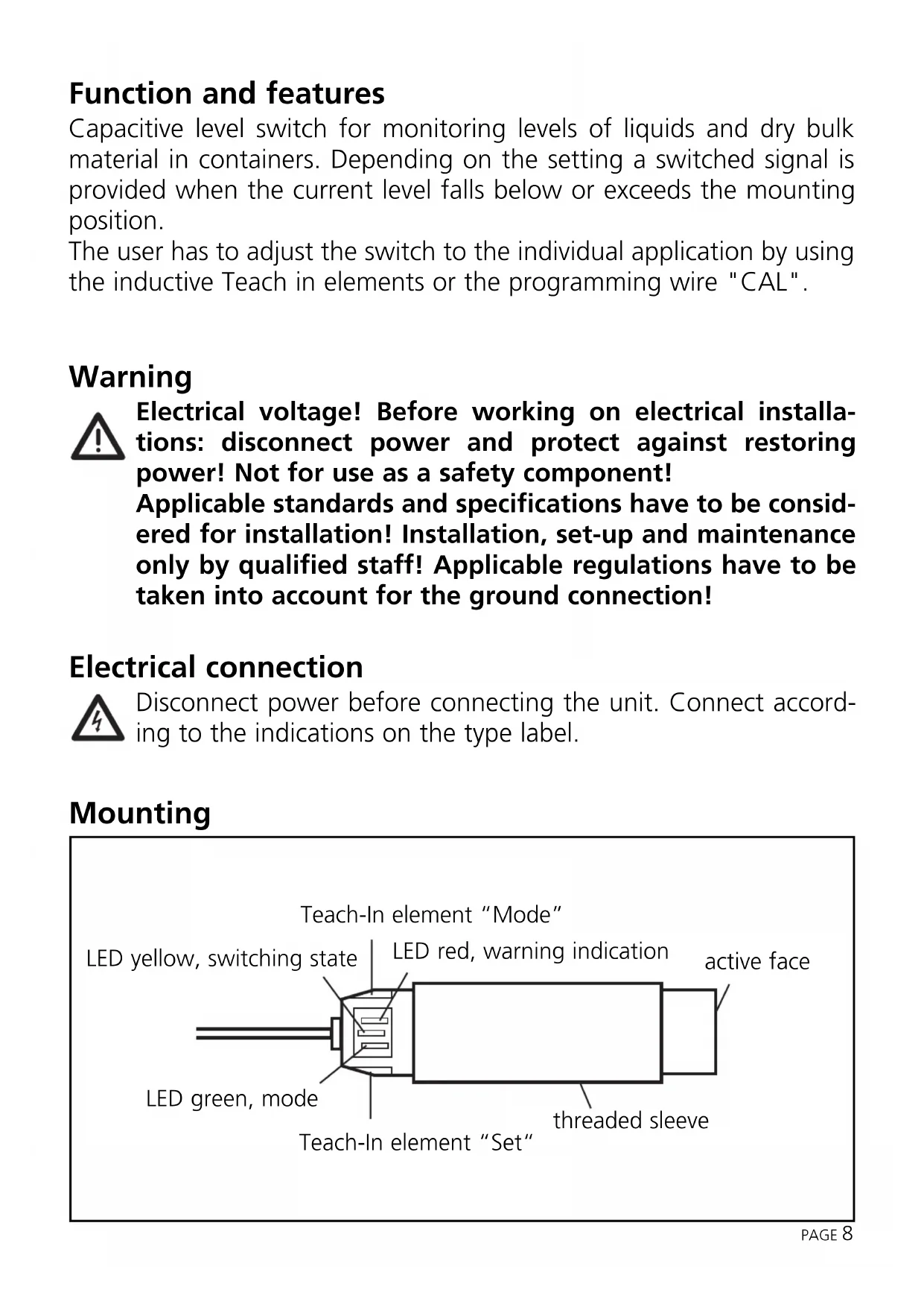
Function and features
Capacitive level switch for monitoring levels of liquids and dry bulk material in containers. Depending on the setting a switched signal is provided when the current level falls below or exceeds the mounting position.
The user has to adjust the switch to the individual application by using the inductive Teach in elements or the programming wire "CAL".
Warning

Electrical voltage! Before working on electrical installations: disconnect power and protect against restoring power! Not for use as a safety component!
Applicable standards and specifications have to be considered for installation! Installation, set-up and maintenance only by qualified staff! Applicable regulations have to be taken into account for the ground connection!
Electrical connection
Disconnect power before connecting the unit. Connect according to the indications on the type label.
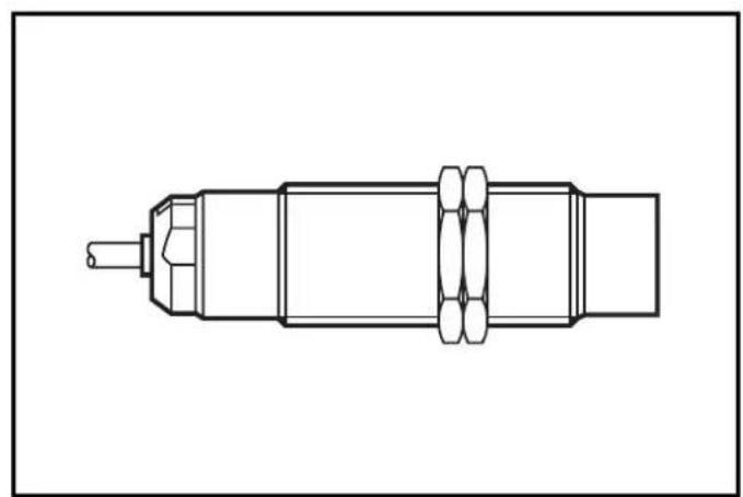
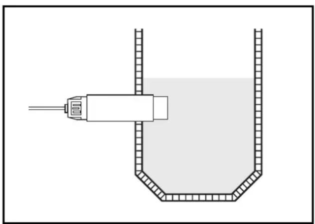
Mounting
The sensor characteristics of a capacitive unit (medium sensitivity, humidity compensation etc.) depend strongly on the mounting position. Consequently, you can fully benefit from the technical advantages of the unit's electronically controlled adjustment when mounting has been completed.
Setting
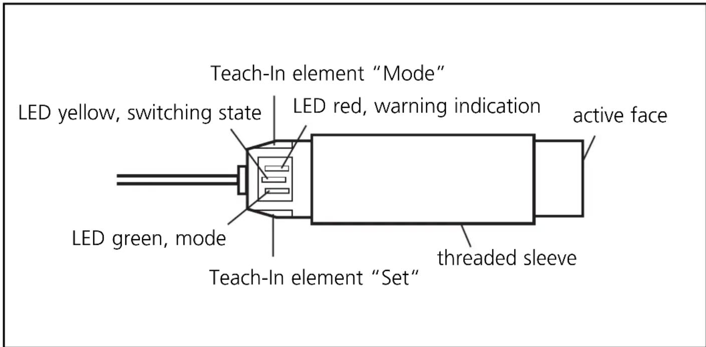
The sensor is set via 2 inductive Teach-In elements (functions *SET and MODE).
If you touch the marked field with a metal object (e.g. screwdriver), the respective Teach-In element is activated.
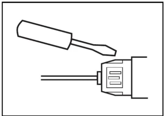
If you remove the object again from the field, the respective Teach-in element is deactivated again. In the text below "actuation" means activating and then deactivating a Teach-In element with a metal object by touching and removing without special time requirements.
- The SET function is also possible via the programming wire "CAL" (not for article KNM.../OF). The programming wire "CAL" is electrically connected with wire "N" to activate the function.
The unit has a microprocessor which enables optimum adjustment to the medium. This process can be carried out as often as you like. The set values are stored in a non-volatile memory (EEPROM) and will be retained even in case of a permanent power failure. At any time a value for the empty state, a value for the full state as well as the output function (normally closed or normally open) are stored in this memory.
The unit has an additional function "uncertain operating range" to monitor and assess the normal operating status. This function provides a signal if the internal sensor signal approaches the switch point before it is actually reached. In this case the red LED is flashing slowly. In clear-cut applications it should only light for short periods, as the level nears the switch point.
Important:
This function is not an error message indicating a failure of the unit. It is to help the user to assess his application. For example it can indicate switch point drift of the sensor caused by considerable soiling before malfunctioning occurs, thus allowing a cleaning process to be started in time or a new empty state setting to be made which takes account of the soiling.
This function also enables comparison of different mounting positions.
Programming
"Operating mode" is the mode when all the normal sensor functions are active.
The following settings are also possible on the unit:
- Setting of the switch point by adjustment to the empty and full states (adjustment mode)
- Setting of the output function as normally closed or normally open (OES mode)
- Electronic lock to avoid unintentional adjustment (locking mode)
Display functions, overview
| LED | State Display | |
| LED green | operating mode off adjustment mode empty slow flashing (1Hz) adjustment mode full fast flashing (2Hz) OES mode slow flashing (1Hz) locking mode off | |
| LED yellow | output disabled off output enabled on OES mode, nc slow flashing (1Hz), together with LED green | |
| LED red uncertain operating range slow flashing (1Hz) error message fast flashing (2Hz) | ||
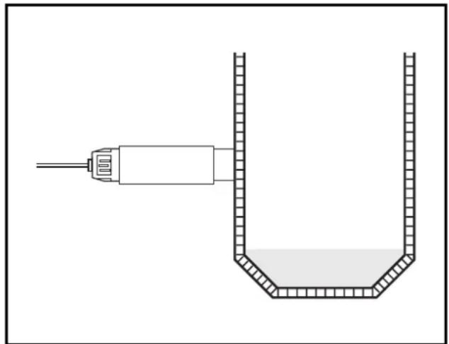
- Adjustment to empty (adjustment mode)
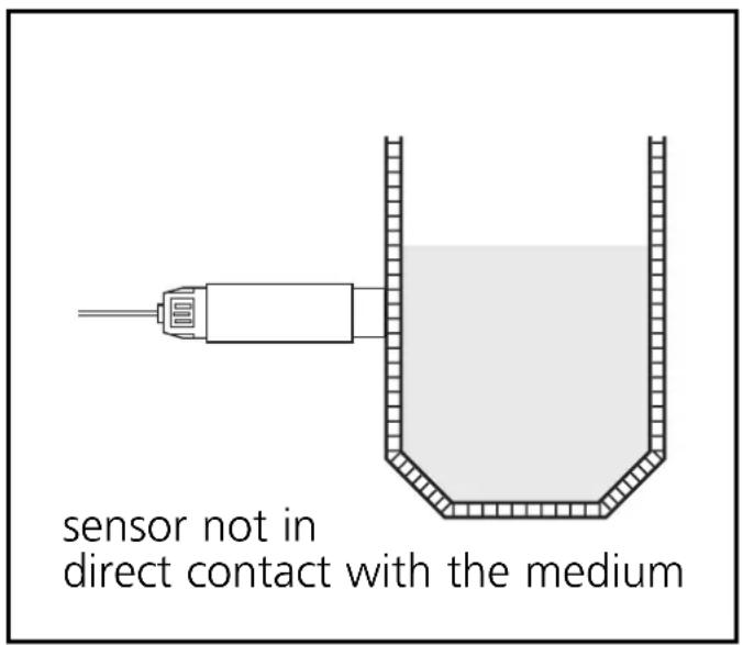
Ensure that the medium to be detected is not in the sensing area of the sensor. Activate the *Teach-In element "SET" for max. 5 s. The green LED flashes slowly. When the element is deactivated, the measured value for the empty state is stored. The unit returns to the operating mode.
Note:
When the unit is adjusted to the empty state, it automatically suggests a possible measured value for the full state. Any measured value for the full state which may have been stored previously is overwritten. This suggested measured value is calculated on the basis of the empty state which has just been measured and a signal distance set at the factory. Under normal conditions safe functioning is guaranteed without adjustment to the full state.
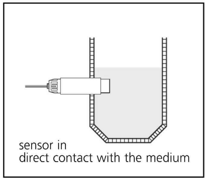
- Adjustment to full (adjustment mode)
Ensure that the medium to be detected is in the sensing area of the sensor.
Activate the *Teach-In element "SET" for min. 5 s and max. 10 s. First the green LED flashes slowly and after 5 s it flashes quickly. By deactivating the element the measured value for the full state is read.
The unit returns to the operating mode. You can repeat the adjustment to the full state as often as you like. The adjustment to the full state does not change the measured value for the empty state stored previously. This enables optimum adaptation of the sensor to changing media in the same vessel for example.
Note:
The adjustment to the full state is not absolutely necessary for the functioning of the unit but it is recommended. On the basis of the values for the empty state/full state the internal microprocessor determines the optimum position of the switching thresholds between the two states. If you use both adjustment criteria (adjustment to the empty/full states), the maximum operational reliability possible for your individual application is guaranteed.
- The SET function is also possible via the programming wire "CAL" (not for article KNM.../OF). The programming wire "CAL" is electrically connected with wire "N" to activate the function.
Error messages:
If the adjustment to the empty/full state is not possible, the red LED flashes quickly (approx. 2 Hz) after the adjustment attempt.
To erase this error message, press a Teach-In element (no matter which) once or switch off the operating voltage for a short time. The values successfully set so far remain unchanged.
Possible reasons for an error message:
-
The signal difference between the empty/full state is too small (e.g. adjustment to the empty and full state without appropriate change of the level)
-
The signal change between the empty and the full state is in the wrong order (e.g. adjustment to the empty state when the vessel is full and to the full state when the vessel is empty)
-
Adjustment to the empty state outside the operating range (e.g. adjustment to the empty state with direct contact with an electrically grounded medium, for example when the sensing face is immersed into water)
- Electronic error or damage of the unit in the sensing area
- Internal error (can only be erased by switching off the operating voltage for a short time, hardware reset)
Setting normally closed/open (OES mode)
The switching output of the unit can be used as normally closed or normally open contact.
First the OES mode must be activated.
Activate the OES mode:
Activate both Teach-In elements "SET" and "MODE" simultaneously for at least 5 s (you need two screwdrivers or similar metal objects).
Now the unit displays the current output function (normally closed or normally open).
Normally open: only the green LED flashes slowly
Normally closed: both the green and the yellow LED are flashing. By actuating the Teach-In element "SET" you can change between the two output functions as often as you like.
Deactivate the OES mode:
There are different ways of deactivating the OES mode and returning to the operating mode.
- In the OES mode actuate the Teach-In element "MODE"
- If after activation of the OES mode no button is pressed for 30~s , the unit automatically returns to the operating mode without any changes being made.
- If you have already pressed the Teach-In element "SET" in the OES mode and no button is pressed for 30~s , the unit automatically returns to the operating mode and stores the last output function set (normally closed or normally open).
Activate/deactivate the electronic lock (locking mode)
Activate the *Teach-In element "SET" for min. 10 s.
If this process is started when the unit is unlocked, the green LED flashes slowly first, then faster. After 10 s all LEDs go off. When the *TeachIn element "SET" is deactivated, the unit is locked and all setting functions are disabled. The unit returns to the operating mode.
If this process is started when the unit is locked, the green LED does not react first to avoid any hint to a hidden function. After 10 s all LEDs go off (if the unit is in an operating mode where no LEDs light or are flashing, the green LED flashes once briefly to indicate that 10 s have elapsed.). When the *Teach-In element "SET" is deactivated, the unit is unlocked and all setting functions can be used again. The unit returns to the operating mode.
- The SET function is also possible via the programming wire "CAL" (not for article KNM.../OF). The programming wire "CAL" is electrically connected with wire "N" to activate the function.
Operation
Check whether the unit functions properly. Indication by LEDs.

- Function and features
- Warning
- Electrical connection
- Mounting
- Setting
- Important:
- Programming
- - Adjustment to empty (adjustment mode)
- Note:
- - Adjustment to full (adjustment mode)
- Error messages:
- Setting normally closed/open (OES mode)
- Activate the OES mode:
- Deactivate the OES mode:
- Activate/deactivate the electronic lock (locking mode)
- Operation
Brand : IFM
Model : KN0001
Category : Gas detector