
SD8001 - Gas detector IFM - Free user manual and instructions
Find the device manual for free SD8001 IFM in PDF.


| Product Type | Gas detector for industrial use |
| Product Name | SD8001 |
| Brand | IFM |
| Dimensions (H x W x D) | 120 mm x 70 mm x 40 mm |
| Weight | Approx. 200 g |
| Power Supply | 12-24 V DC |
| Power Consumption | < 2 W |
| Detection Method | Catalytic combustion |
| Detected Gases | Combustible gases (methane, propane, etc.) |
| Measurement Range | 0-100% LEL |
| Response Time | < 30 seconds |
| Output Signal | 4-20 mA or relay (configurable) |
| Operating Temperature | -20°C to +60°C |
| Humidity Range | 10-95% RH (non-condensing) |
| Protection Rating | IP65 |
| Safety Certifications | CE, ATEX (if applicable) |
| Alarm Output | Audible (85 dB) and visual (LED) |
| Maintenance | Calibrate every 6 months; clean sensor as needed |
| Warranty | 2 years |
| Included Accessories | Mounting bracket, manual |
Frequently Asked Questions - SD8001 IFM
User questions about SD8001 IFM
0 question about this device. Answer the ones you know or ask your own.
Ask a new question about this device
Download the instructions for your Gas detector in PDF format for free! Find your manual SD8001 - IFM and take your electronic device back in hand. On this page are published all the documents necessary for the use of your device. SD8001 by IFM.
USER MANUAL SD8001 IFM
Operating instructions Compressed air meter
efector300
SD8001
80004720 / 00 10 / 2013

natural_image
Line drawing of a handheld electronic device with a cylindrical shaft and control panel (no text or symbols)UK
Contents
1 Preliminary note....4
1.1 Symbols used ....4
2 Safety instructions ....4
3 Functions and features ....5
4 Function....5
4.1 Processing of the measured signals....5
4.2 Volumetric flow monitoring....5
4.3 Consumed quantity monitoring (totalizer function) 6
4.3.1 Consumed quantity monitoring with pulse output......6
4.3.2 Consumed quantity monitoring with preset meter 6
4.4 Monitoring of temperatures....6
4.5 Volumetric flow monitoring / switching function 6
4.6 Volumetric flow monitoring / analogue function .....7
5 Installation....8
5.1 Installation location 8
5.2 Installation conditions ....8
5.3 Mounting position 9
5.4 Installation in pipes 10
6 Electrical connection....10
7 Operating and display elements 11
8 Menu....12
8.1 Menu structure....12
8.2 Explanation of the menu....13
9 Parameter setting 14
9.1 General parameter setting....14
9.2 Settings for volumetric flow monitoring....15
9.2.1 Settings for limit value monitoring with OUT1....15
9.2.2 Settings for limit value monitoring with OUT2....16
9.2.3 Scaling of the analogue value for volumetric flow 16
9.3 Settings for monitoring of consumed quantities....16
9.3.1 Settings for quantity monitoring by pulse output....16
9.3.2 Settings for quantity monitoring using the preset meter .....16
9.3.3 Settings for meter reset controlled by the program .....16
9.3.4 Switch off the meter reset....17
9.4 User settings (optional)....17
9.4.1 Determine the standard unit of measurement for volumetric flow .....17
9.4.2 Configuration of the standard display 17
9.4.3 Setting the damping of the measured values .....17
9.4.4 Setting the error behaviour of OUT1 / OUT2....17
10.1 Read the set parameters 21
10.2 Changing the display unit in the Run mode....21
10.3 Error indication 21
10.4 General operating conditions....22
11 Technical data and scale drawing....22
12 Factory setting 23
1 Preliminary note
1.1 Symbols used
▶ Instruction
Reaction, result
[...] Designation of buttons, switches or indications
→ Cross-reference

Important note
Non-compliance can result in malfunctions or interference.
2 Safety instructions
- Please read this document prior to installing the unit. Ensure that the product is suitable for your application without any restrictions.
- Work on compressed air equipment as well as mounting, setting for operation and set-up of the unit must be carried out by suitably qualified personnel. When doing so, state of the art, safety and accident prevention regulations must be adhered to.
- Ensure that the installation is at a standstill and no pressure is applied before mounting components into or removing them from compressed air equipment.
- Improper or non-intended use may lead to malfunctions of the unit or to unwanted effects in your application. That is why installation, electrical connection, set-up, operation and maintenance of the unit must be carried out by qualified personnel authorised by the plant operator.
- In all applications test the compatibility of the product materials ( 11 Technical data and scale drawing) with the media to be measured.
For the scope of validity cULus: The device shall be supplied from an isolating transformer having a secondary Listed fuse rated as noted in the following table.
| Overcurrent protection | ||
| Control-circuit wire size | Maximum protective device rating Ampere | |
| AWG (mm) | 2) | |
| 26 (0.13) 1 | ||
| 24 (0.20) 2 | ||
| 22 (0.32) 3 | ||
| 20 (0.52) 5 | ||
| 18 (0.82) 7 | ||
| 16 (1.3) 10 | ||
3 Functions and features
The unit monitors the standard volume flow of operating compressed air.
It detects the 3 process categories volumetric flow, consumed quantity, medium temperature.
Applications: compressed air equipment.
All data refer to standard volume flow according to DIN ISO 2533, i.e. volume flow at 1013 hPa, 15°C and 0 % relative air humidity.
The general operating conditions of compressed air equipment apply.
Pressure Equipment Directive (PED): Devices with a measuring section comply with art. 3 sec. (3) of the Directive 97/23/EC and are designed and manufactured for stable gases of the fluid group 2 in accordance with sound engineering practice.

4 Function
4.1 Processing of the measured signals
• The unit displays the current process values.
- It generates 2 output signals according to the parameter setting.
OUT1: 3 selection options .... parameter setting switching signal for volumetric flow limit values .... (→ 9.2.1)
or pulse sequence for totalising meter .... (→ 9.3.1)
or switching signal for preset counter .... (→ 9.3.2)
OUT2: 2 selection options
switching signal for volumetric flow limit value ·s·s(9.2.2)
or analogue signal for volumetric flow 9.2.3
4.2 Volumetric flow monitoring
The flow rate is monitored by a calorimetric measuring system, the measured signals by the electronics.
- 2 switching signals for volumetric flow limit values can be provided (output 1 and output 2). For the switching functions 4.5.
- An analogue signal proportional to the volumetric flow (4...20 mA) can be provided on output 2. For the analogue functions → 4.6.
4.3 Consumed quantity monitoring (totalizer function)
The unit has an internal quantity meter which continuously totals the volumetric flow. The sum corresponds to the current consumed quantity since the last reset.
• The current meter count can be indicated.
- In addition the value before the last reset is stored. This value can also be indicated.
The meter saves the totalled consumed quantity every 10 minutes. After a power failure this value is available as the current meter count. If a time-controlled reset is set, the elapsed time of the set reset interval is also stored. So the possible data loss can be maximum 10 minutes.
The meter can be reset as follows:
• Manual reset ( 9.3.3).
• Time-controlled automatic reset ( 9.3.3).
4.3.1 Consumed quantity monitoring with pulse output
Output 1 provides a counting pulse if the value set in [lmPS] is reached ( 9.3.1).
4.3.2 Consumed quantity monitoring with preset meter
2 types of monitoring are possible:
• Time-dependent quantity monitoring
- Settings: [ImPS] = quantity x, [ImPR] = [no], [rTo] = time t.
- If the quantity x is reached during the time t, output 1 switches and remains switched until the meter is reset.
- If the quantity x has not been reached after the time t, the meter is automatically reset and counting starts again; output 1 does not switch.
• Quantity monitoring not time-dependent
- Settings: [ImPS] = quantity x, [ImPR] = [no], [rTo] = [OFF].
- If the quantity x is reached, output 1 switches and remains switched until the meter is reset.
4.4 Monitoring of temperatures
- The unit detects the current system temperature and shows it on the display (→ chapter 10.2 Changing the display unit in the Run mode).
4.5 Volumetric flow monitoring / switching function
OUTx changes its switching state if it is above or below the set switching limits (SPx, rPx). The following switching functions can be selected:
• Hysteresis function / normally open (fig. 1): [OUx] = [Hno].
• Hysteresis function / normally closed (fig. 1): [OUx] = [Hnc].
First the set point (SPx) is set, then the reset point (rPx) at the requested distance.
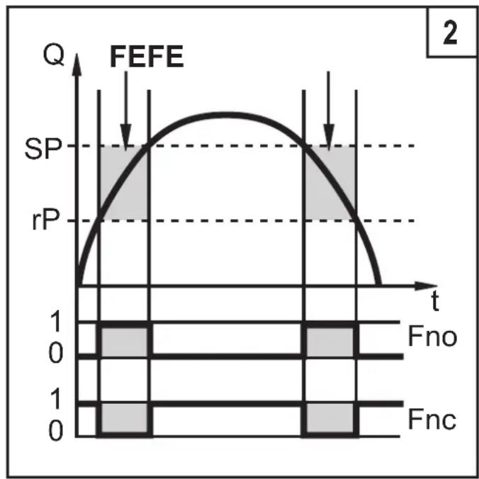
• Window function / normally open (fig. 2): [OUx] = [Fno].
• Window function / normally closed (fig. 2): [OUx] = [Fnc].
The width of the window can be set by means of the distance between SPx and rPx. SPx = maximum value, rPx = minimum value.

line
| t | Q | | ---- | ----- | | 0 | SP | | 1 | rP | | 2 | HY | | 3 | 0 |HY = hysteresis; FE = window
line
| t | Q | | ---- | ----- | | 0 | 0 | | 1 | SP | | 2 | SP | | 3 | rP | | 4 | 0 |When set to the window function the set and reset points have a fixed hysteresis of 0.25 % of the final value of the measuring range. This keeps the switching state of the output stable if the volumetric flow varies slightly.
4.6 Volumetric flow monitoring / analogue function
- The analogue start point [ASP] determines at which measured value the output signal is 4 mA.
- The analogue end point [AEP] determines at which measured value the output signal is 20 mA.
Minimum distance between [ASP] and [AEP] = 25 % of the final value of the measuring range.
Factory setting Measuring range scaled

line
| Q | I [mA] | | ---- | ------ | | 0 | 4 | | MEW | 20 | | Q | 20 |
line
| Q | I [mA] | | ---- | ------ | | 0 | 3.6 | | ASP | 4 | | AEP | 20 | | MEW | 20 |MEW = final value of the measuring range
In the set measuring range the output signal is between 4 and 20 mA.
It is also indicated:
• Volumetric flow above the measuring range: output signal > 20 mA.
- Flow rate below the measuring range: output signal between 3.6 and 4 mA.
5 Installation

The rules and regulations for the installation and operation of compressed air equipment must be observed.
5.1 Installation location
• Behind the cold dryer / near the load.
- If compressed air is fed into the main pipe through parallel pipes, the unit should be mounted in the main pipe.
• Installation after the maintenance unit is also possible. If oil is used for the loads, the unit must be mounted before the oiler.
5.2 Installation conditions
To achieve the specified measurement accuracy, the following mounting conditions must be adhered to: defined inflow / outflow pipe lengths, defined flow cross-sectional area, fixed installation depth and correct positioning of the measuring elements.
The unit is delivered mounted on a pipe section meeting these conditions.
In case of turbulances at the inflow side additional baffled pipes (B) are recommended:
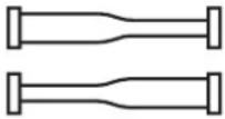 | changes to the pipe diameter B = 5 x pipe diameter |
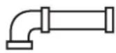 | 90° elbow B = 5 x pipe diameter |
 | two 90° elbows, one plane B = 10 x pipe diameter |
 | two 90° elbows, two planes B = 15 x pipe diameter |
| valve, slide B = 35 x pipe diameter |
5.3 Mounting position
- Permitted mounting positions: pipe length vertical, any position (fig. 1, 2), pipe length horizontal, unit vertical (fig. 3, 5), unit on side, pipe length left (fig. 4).
- Avoid the mounting position shown in fig. 6 (unit on side, pipe length right). If the flow rate is low, the specified measurement accuracy cannot be adhered to.

5.4 Installation in pipes
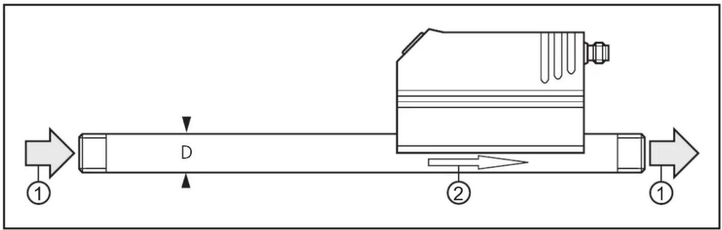
Integrate the pipe length so that the direction of flow (1) and the marking arrow (2) show in the same direction.
6 Electrical connection

The unit must be connected by a qualified electrician.
The national and international regulations for the installation of electrical equipment must be adhered to.
Voltage supply to EN50178, SELV, PELV.
▶ Disconnect power.
▶ Connect the unit as follows:
| 2 switching outputs 1 switching output / 1 analog output | |
 | 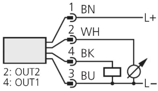 |
OUT1: switching signal or pulse sequence pnp
OUT2: switching signal pnp or analogue signal (I)
Core colours of ifm sockets:
1 = BN (brown), 2 = WH (white), 3 = BU (blue), 4 = BK (black).
7 Operating and display elements

| 1 to 8: Indicator LEDs |
| - LED 1 = current volumetric flow in standard cubic feet/minute (scfm).- LED 2 = current volumetric flow in standard cubic feet/hour (scfh).- LED 3 = current consumed quantity since the last reset in standard cubic feet (scf).- LED 3 flashing = consumed quantity before the last reset in standard cubic feet (scf).- LEDs 3 and 5 = current consumed quantity since the last reset in 10standard cubic feet.- LEDs 3 and 5 flashing = consumed quantity before the last reset in 10standard cubic feet.- LED 4 = current medium temperature in °F.- LED 6 = not used.- LED 7, LED 8 = switching state of the corresponding output. |
| 9: Alphanumeric display, 4 digits |
| - Indication of the current volumetric flow (if [SELd] = [FLOW] is set).- indication of the meter count (if [SELd] = [TOTL] is set).- indication of the current medium temperature (→ 10.2).- indication of the parameters and parameter values. |
| 10: Mode/Enter pushbutton |
| - Selection of the parameters and acknowledgement of the parameter values. |
| 11: Set pushbutton |
| - Setting of the parameter values (scrolling by holding pressed, incremental by pressing briefly).- Change of the display unit in the normal operating mode (Run mode). |
8 Menu
8.1 Menu structure

flowchart
graph TD
    A["1200"] --> B["scfm"]
    B --> C["scfh"]
    C --> D["scf"]
    D --> E["(scf)*"]
    E --> F["°F"]
    F --> G["H1"]
    G --> H["900"]
    H --> I["LO"]
    I --> J["0"]
    J --> K["FOU1"]
    K --> L["OFF"]
    L --> M["FOU2"]
    M --> N["OFF"]
    N --> O["dAP"]
    O --> P["06"]
    P --> Q["rTo"]
    Q --> R["OFF"]
    R --> S["d,S"]
    S --> T["d3"]
    T --> U["Un1"]
    U --> V["SCFH"]
    V --> W["SEld"]
    W --> X["FLOW"]
    X --> Y["rES"]
    Y --> Z["----"]

    subgraph RUN
        A
        B
        C
        D
        E
        F
        G
        H
        I
        J
        K
        L
        M
        N
        O
        P
        Q
        S
        T
        U
        V
        W
        X
        Y
        Z
    end

    SP1 -->|S| IMPS
    IMPS -->|S| 0.120
    rP1 -->|S| 1460
    1460 --> IMPP
    IMPP -->|S| YES_no
    OU1 -->|S| Hno_Hnc_Fno_Fnc_ImP
    OU2 -->|S| Hno_Hnc_Fno_Fnc_I
    SP2 -->|S| 3000
    3000 --> ASP
    ASP -->|S| 0
    rP2 -->|S| 2960
    2960 --> AEP
    AEP -->|S| 7945
    EF -->|S|
    EF --> I200
    scfm -->|S|
    HI -->|S|
    LO -->|S|
    FOU1 -->|S|
    FOU2 -->|S|
    dAP -->|S|
    rTo -->|S|
    d,S -->|S|
    Un1 -->|S|
    SELd -->|S|
    rES -->|S|
⑧ = [Mode/Enter] / ⑤ = [Set]
scf = current meter count in standard cubic feet
(scf)* = stored meter count in standard cubic feet
8.2 Explanation of the menu
| SP1/rP1 | Maximum / minimum value for volumetric flow, at which OUT1 changes its switching status. |
| ImPS Pulse | value. |
| ImPR | Pulse repetition active (= pulse output) or not active (= function preset meter). |
| OU1 | Output function for OUT1 (volumetric flow or consumed quantity):- Switching signal for limit values: hysteresis function or window function, normally open or normally closed.- Pulse or switching signal for quantity meter. |
| OU2 | Output function for OUT2 (volumetric flow):- Switching signal for limit values: hysteresis function or window function, normally open or normally closed.- Analogue signal: 4-20 mA. |
| SP2/rP2 | Maximum / minimum value for volumetric flow, at which OUT2 changes its switching status. |
| ASP Analogue | ue start value for volumetric flow. |
| AEP Analogue | ue end value for volumetric flow. |
| EF Extended | functions / opening of menu level 2. |
| HI / LO | Maximum / minimum value memory for volumetric flow. |
| FOU1 | Behaviour of output 1 in case of an internal fault. |
| FOU2 | Behaviour of output 2 in case of an internal fault. |
| dAP | Measured value damping / damping constant in seconds. |
| rTo | Meter reset: manual reset / time-controlled reset. |
| diS | Update rate and orientation of the display. |
| Uni | Standard unit of measurement for volumetric flow: standard cubic feet/minute or standard cubic feet/hour. |
| SELd | Standard process category of the display: volumetric flow value / meter count. |
| rES | Restore factory setting. |
9 Parameter setting
During parameter setting the unit remains in the operating mode. It continues its monitoring function with the existing parameters until the parameter setting has been completed.
9.1 General parameter setting
3 steps must be taken for each parameter set:
| 1 | Parameter selection► Press [Mode/Enter] until the requested parameter is displayed. |  |
| 2 | Setting of the parameter value► Press [Set] and keep it pressed.> Current setting value of the parameter flashes for 5 s.> After 5 s: The setting value is changed: incremental by pressing briefly or scrolling by holding pressed. |  |
| Numerical values are incremented continuously. If the value is to be reduced: let the display move to the maximum setting value. Then the cycle starts again at the minimum setting value. | ||
| 3 | Acknowledgement of the parameter value► Press [Mode/Enter] briefly.> The parameter is displayed again. The new setting value is stored. |  |
| Setting of other parameters► Start again with step 1. | ||
| Finishing the parameter setting► Press [Mode/Enter] several times until the current measured value is displayed or wait for 15 s.> The unit returns to the operating mode. | ||
• Change from menu level 1 to menu level 2
| ► Press [Mode/Enter] until [EF] is displayed. |  |
| ► Press [Set] briefly.> The first parameter of the sub-menu is displayed (here: [HI]). |  |
- Locking / unlocking
The unit can be locked electronically to prevent unintentional wrong settings.
| ▶ Make sure that the unit is in the normal operating mode. ▶ Press [Mode/Enter] + [Set] for 10 s. > [Loc] is displayed. |  |
| During operation: [Loc] is briefly displayed if you try to change parameter values. | |
| ▶ Press [Mode/Enter] + [Set] for 10 s. > [uLoc] is displayed. | 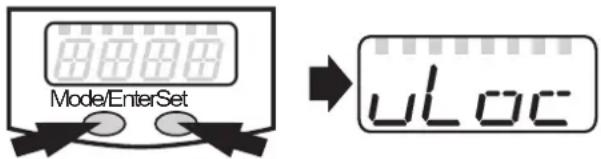 |
When delivered: unlocked.
- Time out:
If during parameter setting no pushbutton is pressed for 15 s, the unit exits the parameter setting mode. The parameter value is not changed.
9.2 Settings for volumetric flow monitoring
9.2.1 Settings for limit value monitoring with OUT1
▶ Select [OU1] and set the switching function:
[Hno] = hysteresis function/normally open,
[Hnc] = hysteresis function/normally closed,
[Fno] = window function/normally open,
[Fnc] = window function/normally closed.
▶ Select [SP1] and set the value at which the output switches.
▶ Select [rP1] and set the value at which the output switches back.
OU I SP I -P I
9.2.2 Settings for limit value monitoring with OUT2
| ▶ Select [OU2] and set the switching function:[Hno] = hysteresis function/normally open,[Hnc] = hysteresis function/normally closed,[Fno] = window function/normally open,[Fnc] = window function/normally closed.▶ Select [SP2] and set the value at which the output switches.▶ Select [rP2] and set the value at which the output switches back. |  |
9.2.3 Scaling of the analogue value for volumetric flow
| ▶ Select [OU2] and set the function:[I] = current signal proportional to volumetric flow (4...20 mA);▶ Select [ASP] and set the value at which the minimum output value is provided.▶ Select [AEP] and set the value at which the maximum output value is provided. |  |
9.3 Settings for monitoring of consumed quantities
9.3.1 Settings for quantity monitoring by pulse output
| ▶ [Select [OU1] and set [lmP].▶ Select [lmPS] and set the volumetric flow quantity at which 1 pulse is provided (→9.6).▶ Select [lmPR] and set [YES]> Pulse repetition is active. Output 1 provides a counting pulse when the value set in [lmPS] is reached. |  |
9.3.2 Settings for quantity monitoring using the preset meter
| ▶ Select [OU1] and set [ImP].▶ Select [ImPS] and set the volumetric flow quantity at which output 1 switches (→9.6).▶ Select [ImPR] and set [no]> Pulse repetition is not active. The output switches ON if the value set in [ImPS] is reached. It remains switched until the meter is reset. |  |
9.3.3 Settings for meter reset controlled by the program
| ▶ Select [rTo] and continue with a) or b).a) Reset the meter manually▶ Press [Set] until [rES.T] is displayed, then press [Mode/Enter] briefly.b) Enter the value for time-controlled reset▶ Press [Set] until the requested value is displayed (intervals from 1 hour to 8 weeks), then press [Mode/Enter] briefly. |  |
9.3.4 Switch off the meter reset
| ▶ Select [rTo] and set [OFF]. The meter is only reset after overflow (= factory setting). | r- To |
9.4 User settings (optional)
9.4.1 Determine the standard unit of measurement for volumetric flow
| ▶ Select [Uni] and set the unit of measurement:[SCFm] = flow rate in standard cubic feet / minute.[SCFH] = flow rate in standard cubic feet / hour.The setting only has an effect on the volumetric flow value. The counter values (consumed quantity) are automatically displayed in the unit of measurement providing the highest accuracy. | Uni |
9.4.2 Configuration of the standard display
| ▶ Select [SELd] and determine the standard process category.[FLOW] = display shows the current volumetric flow value in the standard unit of measurement.[TOTL] = display indicates the current meter count in scf or 1000 scf.▶ Select [diS] and determine the update rate and orientation of the display:[d1] = update of the measured values every 50 ms.[d2] = update of the measured values every 200 ms.[d3] = update of the measured values every 600 ms.[rd1], [rd2], [rd3] = display as for d1, d2, d3; rotated by 180°.[OFF] = the display is switched off in the operating mode. | SELDi S |
9.4.3 Setting the damping of the measured values
| ▶ Select [dAP] and the damping constant in seconds (t value 63 %). | dAP |
9.4.4 Setting the error behaviour of OUT1 / OUT2
| ▶ [Select [FOU1] and determine the value:[On] = output 1 switches ON in case of an error.[OFF] = output 1 switches OFF in case of an error.[OU] = output 1 switches irrespective of the error as defined with the parameters.▶ Select [FOU2] and determine the value:[On] = output 2 switches ON in case of an error, the analogue signal goes to the upper end stop value.[OFF] = output 2 switches OFF in case of an error, the analogue signal goes to the lower end stop value.[OU] = output 2 switches irrespective of the error as defined with the parameters. The analogue signal corresponds to the measured value. | FOU1FOU2 |
| ▶ Select [HI] or [LO] and press [Set] briefly.[HI] = maximum value, [LO] = minimum value.Delete memory:▶ Select [HI] or [LO].▶ Press [Set] and keep it pressed until [----] is displayed.▶ Press [Mode/Enter] briefly.It makes sense to delete the memories as soon as the unit works under normal operating conditions for the first time. |  |
9.5.2 Reset all parameters to the factory setting
| ▶ Select [rES], then press [Set] and keep it pressed until [----] is displayed. ▶ Press [Mode/Enter] briefly.The factory setting is listed at the end of the instructions (→ 12 Factory setting).It makes sense to write your own settings in this table before executing the function. |  |
9.6 Setting of the preset meter / pulse value (ImPS)
7 setting ranges are available:
| LED indication in steps of value | |||||||||||
| 1 3 | 0 .1 2 0 ... | 9 | 9 | 8 | 0 | 0.020 | scf 0.12 | 0..9 | 980 scf | ||
| 2 3 | 1 0 .0 0 ... | 9 | 9 | 9 | 8 | 0.02 | scf 10.00 | ... | 99.98 scf | ||
| 3 3 | 1 0 0 .0 ... | 9 | 9 | 9 | 9 | 0.1 | scf 100.0 | ... | 999.9 scf | ||
| 4 3 | 1 0 0 0 ... | 9 | 9 | 9 | 1 | scf | 1000..9 | 999 scf | |||
| 5 | 3 + 5 | 1 | 0 | .0 | 0 | ... | 9 | 9 .9 | 9 | 10 scf | |
| 6 | 3 + 5 | 1 | 0 | 0 | .0 | ... | 9 | 9 | 9 .9 | 100 scf | |
| 7 | 3 + 5 | 1 | 0 | 0 | ..4 | 0 0 0 | 1000 scf | 1 000 000 scf ...4 000 000 scf | |||
UK
Setting operation:
▶ Ensure that [OU1] is set to [ImP].
▶ Select [lmPS], press [Set] and keep it pressed.
The current numerical value flashes for 5 s, then one of the 4 digits becomes active (digit flashes, can be changed).
▶ Set the requested value as indicated in the following table.
First select the requested setting range. Then set the figure from the left digit to the right digit.
▶ Press [Mode/Enter] briefly when all 4 digits are set.
As soon as the first digit flashes there are 3 options:
| ▶ Press [Set] once | The flashing digit is increased. 9 is followed by 0 - 1 - 2, etc. |
| 8 1 2 3 | |
| [Set] pressed 1 x 9 1 2 3 | |
| [Set] pressed 1 x 0 1 2 3 | |
| [Set] pressed 1 x 1 1 2 3 | |
| ► Press [Set] and keep pressed. | The flashing digit is increased, 9 is followed by 0 and the first new digit (left) becomes active.[Set] permanently pressed .1 9 3[Set] kept pressed .1 0 3 |
| If digit 1 is increased this way, the display changes to the next higher setting range (9 is followed by 10).[Set] permanently pressed .1 2 3[Set] kept pressed 1 0 .1 2 | |
| ► Press no pushbutton for 3 s. | The digit following on the right flashes (= becomes active). If the fourth digit flashes unchanged for 3 s, digit 1 becomes active again (if the value of digit 1 is >0).no pushbutton pressed; after 3 s .1 2 3after 3 s .1 2 3after 3 s .1 2 3after 3 s .1 2 3 |
| If digit 1 has the value “0”, the display changes to the next lower setting range.no pushbutton pressed; after 3 s 0 1 .2 3after 3 s 0 1 .2 3after 3 s 0 1 .2 3after 3 s (new digit 4 active and set to 0) 1 .2 3 0after 3 s (new digit 1 active) 1 .2 3 0 |
Highlighted grey (1) = flashing digit
Note: If [Set] is pressed continuously, the display moves through all setting ranges; after the end value it jumps back to the start value. Release [Set] briefly and start the setting again.
10 Operation
Correct operation and compliance with the measurement accuracy can only be ensured if the environmental conditions specified in the Technical data are adhered to. Ensure that the maximum pressure range, measuring range and permitted operating temperature are not exceeded.
After power on and expiry of the power-on delay time (approx. 0.5 s) the unit is in the Run mode (= normal operating mode). It carries out its measurement and evaluation functions and generates output signals according to the set parameters.
• Operation indication → chapter 7 Controls and indicating elements.
- During the power-on delay time the outputs are switched as programmed: ON for NO function (Hno / Fno) and OFF for NC function (Hnc / Fnc).
- If output 2 is configured as analogue output, the output signal is at the maximum value during the power-on delay time.

10.1 Read the set parameters
▶ Press [Mode/Enter] until the requested parameter is displayed.
▶ Press [Set] briefly.
The unit displays the corresponding parameter value for about 15 s. After another 15 s the parameter is displayed again, then the unit returns to the Run mode.
10.2 Changing the display unit in the Run mode
▶ Press [Set] briefly in the Run mode. Press the pushbutton to move to the next display unit.
The unit displays the current measured value for approx. 15 s, the corresponding LED lights.
10.3 Error indication
| [SC1] Short circuit in OUT1.* |
| [SC2] Short circuit in OUT2.* |
| [SC] Short circuit in both outputs.* |
| [OL] Measured value > 120% of the final value of the measuring range. |
| [UL] Measured value < lowest value of the measuring range. |
| [Err] Fault in the measuring probe. |
*The output concerned is switched off as long as the short circuit continues.
These faults are indicated even if the display is deactivated.
10.4 General operating conditions
The unit is maintenance-free for media which will not adhere to the measuring probes.
• From time to time check the measuring probes visually for build-up.
- If necessary, clean them at regular intervals. To do so, use a suitable cleaning liquid (e.g. alcoholic solution).
- Avoid mechanical damage to the measuring probes.
11 Technical data and scale drawing
Technical data and scale drawing at www.ifm.com → Data sheet search → Enter the article number.
12 Factory setting
| Factory setting User setting | ||
| SP1 | 1500 | |
| rP1 | 1460 | |
| ImPS | 0.120 | |
| ImPR | YES | |
| OU1 | Hno | |
| OU2 | Hno | |
| SP2 | 3000 | |
| rP2 | 2960 | |
| ASP | 0 | |
| AEP | 7945 | |
| FOU1 | OFF | |
| FOU2 | OFF | |
| dAP | 0.6 | |
| rTo | OFF | |
| diS | d3 | |
| Uni | SCFH | |
| SELd | FLOW | |
More information at www.ifm.com
- Contents
- Preliminary note
- Symbols used
- Safety instructions
- Functions and features
- Function
- Processing of the measured signals
- Volumetric flow monitoring
- Consumed quantity monitoring (totalizer function)
- Consumed quantity monitoring with pulse output
- Consumed quantity monitoring with preset meter
- Monitoring of temperatures
- Volumetric flow monitoring / switching function
- Volumetric flow monitoring / analogue function
- Installation
- Installation location
- Installation conditions
- Mounting position
- Installation in pipes
- Electrical connection
- Operating and display elements
- Menu
- Menu structure
- Parameter setting
- General parameter setting
- Settings for volumetric flow monitoring
- Settings for limit value monitoring with OUT1
- Settings for limit value monitoring with OUT2
- Scaling of the analogue value for volumetric flow
- Settings for monitoring of consumed quantities
- Settings for quantity monitoring by pulse output
- Settings for quantity monitoring using the preset meter
- Settings for meter reset controlled by the program
- Switch off the meter reset
- User settings (optional)
- Determine the standard unit of measurement for volumetric flow
- Configuration of the standard display
- Setting the damping of the measured values
- Setting the error behaviour of OUT1 / OUT2
- Reset all parameters to the factory setting
- Setting of the preset meter / pulse value (ImPS)
- Setting operation:
- Operation
- Read the set parameters
- Changing the display unit in the Run mode
- Error indication
- General operating conditions
- Technical data and scale drawing
Brand : IFM
Model : SD8001
Category : Gas detector