
Linear 7 115 FA - Speaker HK AUDIO - Free user manual and instructions
Find the device manual for free Linear 7 115 FA HK AUDIO in PDF.
| Product Type | Professional active speaker (Fullrange) |
| Brand and Model | HK Audio Linear 7 115 FA |
| Dimensions (W x H x D) | 45 x 71 x 45 cm (17-23/32 x 27-61/64 x 17-23/32 inches) |
| Weight | 32 kg (70.5 lbs) |
| Power Supply | 100–240 V~, 50-60 Hz, 1 A (rated consumption according to EN 62368-1) |
| Mains Connectors | 1x Powercon NAC3 In (no Link output) |
| Output Power (Peak) | 2000 W (Class D, bi-amplified) |
| Max. SPL (10% THD) | 129 dB half space (average 70 Hz - 12 kHz); 134 dB peak |
| Frequency Response +/-3 dB | 57 Hz - 19 kHz; -10 dB: 54 Hz - 19 kHz |
| Woofer | 1x 15" with 3" voice coil |
| Tweeter Driver | 1" with 1.7" voice coil |
| Horn | CD 60° x 40°, rotatable |
| Active Crossover Frequency | 1.5 kHz, FIR X-Over, 60 dB/oct. |
| DSP Processing | 10-band parametric EQ, delay, limiter, polarity, mute, high/low-pass filters |
| Factory Presets | Flat, Boost, Low Cut, Remote |
| Analog Inputs | 1x XLR/jack combo balanced (Input) |
| Analog Outputs | 1x XLR Thru, 1x XLR DSP Out (processed signal or audio network) |
| Ethernet Network | 2x Ethercon (RJ45) – In/Thru, Milan (AVB) compatible |
| Clustering Angle | 60° (angled side panels) |
| Tripod Mount | DuoTilt 3°/7° (for 35 mm pole) |
| Suspension Mounting Points | 3x M8 (AP-8) |
| Handles | 2x MultiGrip |
| Cabinet Material | Composite (birch plywood/MDF) |
| Grille | 2 mm metal with black acoustic foam |
| Maintenance and Cleaning | Clean only with a dry cloth. Do not open the cabinet. Have any repairs carried out by a qualified specialist. |
| Safety | Do not expose to humidity or rain, do not open, observe mounting and load instructions for tripods, use only HK Audio accessories. |
| Operating Conditions | Indoor use, moderate climate zones. Do not use near water or heat sources. |
| Warranty | Registration within 30 days at www.hkaudio.com |
Frequently Asked Questions - Linear 7 115 FA HK AUDIO
User questions about Linear 7 115 FA HK AUDIO
0 question about this device. Answer the ones you know or ask your own.
Ask a new question about this device
Download the instructions for your Speaker in PDF format for free! Find your manual Linear 7 115 FA - HK AUDIO and take your electronic device back in hand. On this page are published all the documents necessary for the use of your device. Linear 7 115 FA by HK AUDIO.
USER MANUAL Linear 7 115 FA HK AUDIO
Important Safety Instructions! Read before connecting!
This product has been built by the manufacturer in accordance with IEC 62368-1 and left the factory in safe working order. To maintain this condition and ensure non-risk operation, the user must follow the advice and warning comments found in the operating instructions. If this product shall be used in vehicles, ships or aircraft or at altitudes exceeding 2000 m above sea level, take care of the relevant safety regulations which may exceed the IEC 62368-1 requirements.
WARNING: To prevent the risk of fire and shock hazard, do not expose this appliance to moisture or rain. Do not open case – no user serviceable parts inside. Refer service to qualified service personnel.

This symbol, wherever it appears, alerts you to the presence of regulated dangerous voltage inside the enclosure – voltage that sufficient to constitute a risk of shock.

This symbol, wherever it appears, alerts you to the presence normally accessible hazardous voltage. External wiring connected terminal marked with this symbol must be a “ready made complying with the manufacturers recommendations, or must being installed by instructed persons only.

This symbol, wherever it appears, alerts you to important and maintenance instructions in the accompanying e. Read the manual.

This symbol, wherever it appears, tells you: Take care! Hot To prevent burns you must not touch.

All electrical and electronic products including batteries
should be disposed of separately from the municipal waste stream via designated collection facilities appointed by the government or the local authorities.

Read these instructions. Keep these instructions. Follow all gs and instructions marked on the product and in this manual.
- Do not use this product near water. Do not place the product near water, baths, wash basins, kitchen sinks, wet areas, swimming pools or damp rooms.
- Do not place objects containing liquid on the product – vases, glasses, bottles etc.
- Clean only with dry cloth.
- Do not remove any covers or sections of the housing.
- The set operating voltage of the product must match the local mains supply voltage. If you are not sure of the type of power available consult your dealer or local power company.
- Before connecting the device, please ensure that the mains supply you are using is equipped with adequate protection against short circuiting and grounding faults when the device is plugged in.
- To reduce the risk of electrical shock, the grounding of this product must be maintained. Use only the power supply cord provided with this product, and maintain the function of the center (grounding) pin of the mains connection at any time. Make sure the mains outlet used provides a proper protective ground connection.
- Do not defeat the safety purpose of the polarized or grounding-type plug. A polarized plug has two blades with one wider than the other. A grounding type plug has two blades and a third grounding prong. The wide blade or the third prong are provided for your safety. If the provided plug does not fit into your outlet, consult an electrician for replacement of the obsolete outlet.
- Protect the power cord from being walked on or pinched particularly at plugs, convenience receptacles, and the point where they exit from the device! Power supply cords should always be handled carefully. Periodically check cords for cuts or sign of stress, especially at the plug and the point where the cord exits the device.
- Never use a damaged power cord.
- Unplug this product during lightning storms or when unused for long periods of time.
-
This product can be fully disconnected from mains only by pulling the mains plug at the unit or the wall socket. The product must be placed in such a way at any time, that disconnecting from mains is easily possible.
-
Fuses are to be replaced exclusively by qualified personnel, and then only with fuses of the proper type and rating.
- Refer all servicing to qualified service personnel. Servicing is required when the unit has been damaged in any way, such as:
- When the power cord or plug is damaged or frayed.
- If liquid has been spilled or objects have fallen into the product.
- If the product has been exposed to rain or moisture.
- If the product does not operate normally when the operating instructions are followed.
- If the product has been dropped or the cabinet has been damaged.
- Do not connect external speakers to this product with an impedance lower than the rated impedance given on the product or in this manual. Use only cables with sufficient cross section according to the local safety regulations.
- Keep away from direct sunlight.
- Do not install near heat sources such as radiators, heat registers, stoves or other devices that produce heat.
- This apparatus is for moderate climates areas use, not suitable for use in tropical climates countries.
- Do not block any ventilation openings. Install in accordance with manufacturer's instructions. This product must not be placed in a built-in installation such as a rack unless proper ventilation is provided.
- Always allow a cold device to warm up to ambient temperature, when being moved into a room. Condensation can form inside it and damage the product, when being used without warming up.
- Do not place naked flame sources, such as lighted candles on the product.
- The device must be positioned at least 20 cm/8" away from walls.
- Use only with the cart, stand, tripod, bracket or table specified by the manufacturer or sold with the product. When a cart is used, use caution when moving the cart/product combination to avoid injury from tip-over.
- Use only accessories recommended by the manufacturer, this applies for all kind of accessories, for example protective covers, transport bags, stands, wall or ceiling mounting equipment. In case of attaching any kind of accessories to the product, always follow the instructions for use, provided by the manufacturer. Never use fixing points on the product other than specified by the manufacturer.
- This appliance is NOT suitable to be used by any person or persons (including children) with limited physical, sensorical or mental ability, or by persons with insufficient experience and/or knowledge to operate such an appliance. Children under 4 years of age must be kept away from this appliance at all times.
- Never push objects of any kind into this product through cabinet slots as they may touch dangerous voltage points or short out parts that could result in risk of fire or electric shock.
- This product is capable of delivering sound pressure levels in excess of 90 dB, which may cause permanent hearing damage! Exposure to extremely high noise levels may cause a permanent hearing loss. Wear hearing protection if continuously exposed to such high levels.
- The manufacturer only guarantees the safety, reliability and efficiency of this product if:
- Assembly, extension, re-adjustment, modifications or repairs are carried out by the manufacturer or by persons authorized to do so
- The electrical installation of the relevant area complies with the requirements of IEC (ANSI) specifications.
- The unit is used in accordance with the operating instructions.
- This product is optimized for use with music and speech signals. Using this product with sine wave, square wave or other kind of measuring signals at higher level may lead to severe damage of the product.
General Notes on Safety for Loudspeaker Systems

Mounting systems may only be used for those loudspeaker systems authorized by the manufacturer and only with the mounting accessories specified by the manufacturer in the installation instructions. Read and heed the manufacturer's installation instructions. The indicated load-bearing capacity cannot be guaranteed and the manufacturer will not be liable for damages in the event of improper installation or the use of unauthorized mounting accessories. The system's load-bearing capacity cannot be guaranteed and the manufacturer will not be liable for damages in the event that loudspeakers, mounting accessories, and connecting and attaching components are modified in any way. Components affecting safety may only be repaired by the manufacturer or authorized agents, otherwise the operating permit will be voided.

Installation may be performed qualified personnel only, and then only at pick-points with sufficient load-carrying capacity and in compliance with local building regulations. Use only the mounting hardware specified by the manufacturer in the installation instructions (screws, anchors, etc.). Take all the precautions necessary to ensure bolted connections and other threaded locking devices will not loosen.

Fixed and portable installations (in this case, speakers and mounting accessories) must be secured by two independent safeties to prevent them from falling. Safeties must be able to catch accessories or parts that are loose or may become loose. Ensure compliance with the given national regulations when using connecting, attaching, and rigging devices. Factor potential dynamic forces (jerk) into the equation when determining the proper size and load-bearing capacity of safeties.

Be sure to observe speaker stands' maximum load-bearing capacity. Note that for reasons of design and construction, most speaker stands are approved to bear centric loads only; that is, the speakers' mass has to be precisely centered and balanced. Ensure speaker stands are set up stably and securely. Take appropriate added measures to secure speaker stands, for example when:
- the floor or ground surface does not provide a stable, secure base. - they are extended to heights that impede stability. - high wind pressure may be expected.
- there is the risk that they may be knocked over by people. Special measures may become necessary as precautions against unsafe audience behavior. Do not set up speaker stands in evacuation routes and emergency exits. Ensure corridors are wide enough and put proper barriers and markings in place when setting speaker stands up in passageways. Mounting and dismounting are especially hazardous tasks. Use aids suitable for this purpose. Observe the given national regulations when doing so.


Wear proper protection (in particular, a helmet,
gloves, and safety shoes) and use only suitable means of ascent (ladders, scaffolds, etc.) during installation. Compliance with this requirement is the sole responsibility of the company performing the installation.

WARNING! After installation, inspect the system comprised mounting fixtures and loudspeakers to ensure it is properly d.
The operator of loudspeaker systems (fixed or portable) must regularly inspect or task a third party to regularly inspect all system components in accordance with the given country's regulations and have possible defects repaired immediately. We also strongly recommend maintaining a logbook or the like to document all inspections.
Also be sure to provide sufficient safety margins for the rigging points used for flown systems. Observe the given national regulations when doing so.

Professional loudspeaker systems can produce harmful levels. Even prolonged exposure to seemingly harmless levels (ing at about 95 dBA SPL) can cause permanent hearing damage! More we recommend that everyone who is exposed to high volume produced by loudspeaker systems wears professional hearing vision (earplugs or earmuffs).
Manufacturer: Stamer Musikanlagen GmbH, Magdeburger Str. 8, 66606 St. Wendel, Germany
LINEAR 7
L7 110 XA L7 112 FA L7 112 XA L7 115 FA L7 118 Sub A
Welcome to the HK Audio family!
Thank you for choosing a brand-name product made by our company. Rest assured, we engineered and built it with the greatest care so it will serve you well for many tomorrows to come.

Even if your experience with sound systems runs deep, some things about this product are sure to be new to you. This is why we ask that you do not set this manual aside without reading it first. Be sure to keep it in a safe place for later reference.
Here's wishing you the best sound at every occasion!
Your HK Audio team

Strong electromagnetic interference or electrostatic discharge may prevent the product from functioning normally. If this happens, the product may be returned to normal operation by powering off and on again. Should this not result in the product functioning normally again, please move the product away from the source of disturbance and try again.
Warranty
Use the convenient online registration option at www.hkaudio.com.

http://warranty.hkaudio.com
The registration is only valid if the device is registered within 30 days of the date of purchase.
HK Audio
Technischer Service
Postfach 1509
66595 St. Wendel, Germany
Fax: +49 6851 905 100
1 General Information
Unpacking and Inventorying
When you first unpack your LINEAR 7 speaker cabinet, take a quick inventory to make sure it comes complete with the manual and Powercon mains cable.
2 Connectors and Controls
text_image
Input Thru Gain DSP OutL7 XA/FA models

text_image
Input L Thru Gain 0 dB 3 6 dB-6 dB DSP Out 4 1 2 3 4 R 1 2 5L7 118 Sub A
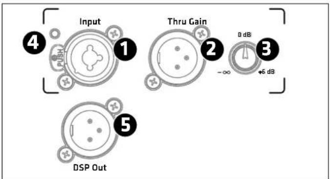
① Input
This XLR/1/4" (6.35 mm) combo jack provides a balanced input for analog signals.
• L7 XA/FA models have one input channel.
- The L7 118 Sub A subwoofer has two separate inputs for the left and right signals. The two channels are equal and merged post-preamp, so you can use either one in mono mode.
2 Thru
Use this parallel, balanced XLR output to send the signal routed into the Input through to other components. This output remains active even when the electronic components are deactivated. The subwoofer has two of these ports.
3 Gain
Use this knob to adjust the input gain for the incoming signal.
- The control range for the XA/FA models sweeps from - (mute) to +6 dB.
- This knob adjusts the gain for both of the L7 118 Sub A's stereo preamp channels in a range of -6 to +6 dB.
The center-notched 12 o'clock position is 0 dB in both cases.
Heads up: The Gain setting does not affect the signal sent to the DSP Out.
4 Input/Limiter LED
This LED lights up green to indicate incoming signals and red to indicate signal peaks. The LED briefly flashes red to tell you the Limiter is responding to signal peaks. If it stays red, turn down the Gain knob.
5 DSP Out
Use this XLR port to forward the signal routed into the Input jack or to forward a digital audio signal streamed* in via Milan™, an AVB-based digital audio network protocol. The onboard DSP can process both types of signals. This means the DSP Out can serve as a network interface that lets you integrate an added powered speaker that is not equipped with Ethernet ports. You can even use it as an audio interface to send audio signals streamed* in to the LINEAR 7 speaker on to other speakers, for example, to powered LINEAR SUB series subwoofers.
In the factory default configuration, the unprocessed input signal goes straight to DSP Out it, regardless of the selected preset and the Gain knob setting.
text_image
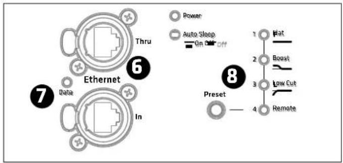
Thru 6 Ethernet 7 Data In Power Auto Sleep On Off 1 2 3 4 8 Preset Flat Boost Low Cut Remote⑥ Ethernet In /Thru
Use the two Ethercon ports to integrate the speaker into a network. They accept RJ45 and Ethercon (NE8 MX, NE8 MX6, NE8 MC) plugs. Use the Ethernet Thru port to forward the network signal.
Always use S/STP or S/FTP cables to shield against electromagnetic interference. We recommend CAT6 cables. A separate manual explains the fi ner points of network integration, remote control functions and audio streaming*.
You will find it on the LINEAR 7 download page at www.hkaudio.com. For a brief description of the DSP functions, see section 8 Preset.
7 Data
This LED lights up orange when data flows through the network connector.

Preset
Use the Preset selection button to call up factory presets or a user preset you can confi gure via the remote DSP CONTROL software. Tap the select button once to scroll through Presets 1 through 4.
A separate manual explains how to program the four remote user presets. You will find it on the LINEAR 7 download page at www.hkaudio.com.
Presets:
| L7 110 XAL7 112 XAL7 112 FA L7 115 FA L7 118 Sub A | |||||
| 1 Flat Flat Flat Flat Front | |||||
| 2 Monitor Monitor | Boost Boost | Cardioid 1 | |||
| 3 | Low Cut | Low Cut | Low Cut | Low Cut | Cardioid 2 |
| 4 | Remote (to access stored settings via the remote HK Audio DSP CONTROL software) | ||||
The L7 XA/FA models' factory presets:
| Flat Delivers | linear response across the full frequency range |
| Monitor | Optimized to dampen the extra bass generated by floor coupling when you set a speaker on its side for use as a monitor |
| Boost | Enhances low-frequency response when you use the mid/high unit a standalone speaker without a subwoofer |
| Low Cut | A high-pass filter optimizes the unit for use as a mid/high unit paired with the L7 118 Sub A |
The L7 118 Sub A's factory presets:
| Front | Standard operating mode for a forward-facing subwoofer |
| Cardioid 1:1 | For cardioid setups with one forward-facing L7 118 Sub A; see section 4.2 for more on this |
| Cardioid 2:1 | For cardioid setups with two forward-facing L7 118 Sub A; see section 4.2 for more on this |
Factory presets 1 to 3 address the speaker only and not the DSP Out.
Heads up: If you are operating the speaker in a network connected to the remote DSP CONTROL software, you can configure the DSP Out independently even when using factory presets 1 to 3. To learn more about this, consult the separate DSP CONTROL manual. You will find it on the LINEAR 7 download page at www.hkaudio.com.
The Remote Preset
| Remote This | lets you call up a user preset that you previously stored via DSP CONTROL for the speaker as well as for the DSP Out. The speakers does not need to be connected to the remote software to do this. |
The remote preset's default setup is identical to factory preset 1 (Flat/Front).
You can access the following DSP functions via the remote DSP CONTROL software and save your settings in user presets:
Fully parametric 10-band EQ with variable fi Iter characteristics for each frequency band, high-pass and low-pass filters with variable filter characteristics, Limiter, Delay, Polarity, Level, and Mute
You can configure these parameters separately and independently for the speaker and its DSP Out.
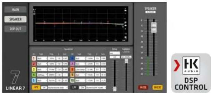
text_image
MAIN SPEAKER DSP BUT 7 LINEAR 7 Speaker 1 2 3 4 5 6 7 8 9 10 11 12 13 14 15 16 17 18 19 20 21 22 23 24 25 26 27 28 29 30 31 32 33 34 35 36 37 38 39 40 41 42 43 44 45 46 47 48 49 50 51 52 53 54 55 56 57 58 59 60 61 62 63 64 65 66 67 68 69 70 71 72 73 74 75 76 77 78 79 80 81 82 83 84 85 86 87 88 89 90 91 92 93 94 95 96 97 98 99 100Screenshot of the remote DSP CONTROL software. You can download this software free of charge at the LINEAR 7 product page at www.hkaudio.com. The speaker and DSP Out parameters are identical, but the powerful onboard DSP lets you configure each set independently.

Power
This rocker switch turns the power on and off. Set it to Power to turn the electronic components on and to Off to disconnect them from the mains power supply. The Power switch does not affect the Powercon Link port. See section 12 below for more on this.

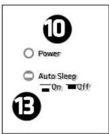
Power-LED
This LED lights up green when the electronic components are getting mains power.

Mains Input
Use the factory-included Powercon mains cord to connect this socket to a power outlet. Insert the push-pull connector and turn it clockwise to make sure the Powercon cord engages and locks.
To unlock it, pull the Powercon plug's locking mechanism towards the cable and turn it counterclockwise.
text_image
10 Power Auto Sleep On Off 13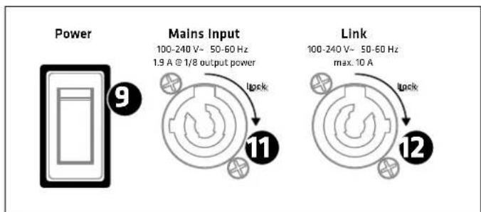
flowchart
graph TD
    A["Power"] --> B["Mains Input"]
    B --> C["100-240 V~ 50-60 Hz\n1.9 A @ 1/8 output power"]
    B --> D["Link"]
    D --> E["100-240 V~ 50-60 Hz\nmax. 10 A"]
    B --> F["Lock"]
    B --> G["Lock"]

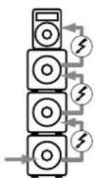
Link (L7 118 Sub A only)
This socket can power up to three additional LINEAR 7 speaker cabinets. Hardwired to the Mains Input, it is not affected by the Power switch setting. The Link circuit goes live the moment you connect the Mains Input to a power source. This is why you must make sure all downstream devices are switched off before you connect them to the Link port.
13 Auto Sleep
Use this recessed button to switch energy-saving Auto Sleep mode on and off. Your speaker leaves the factory with the Auto Sleep button pressed to enable this mode. This function puts the electronic components to sleep when four and a half hours pass without the speaker registering an audio signal, data sent to the Ethercon ports, or an adjustment of a button or knob. The only way to wake it up is by switching the Power button off and on again or patching an analog audio signal into the Input.
Heads up: You cannot wake up the speaker via the Ethercon ports. There is but one way to deactivate the Auto Sleep function – by 'unpressing' the button to set it to the up position.
3 An Overview of the Various LINEAR 7 Models
natural_image
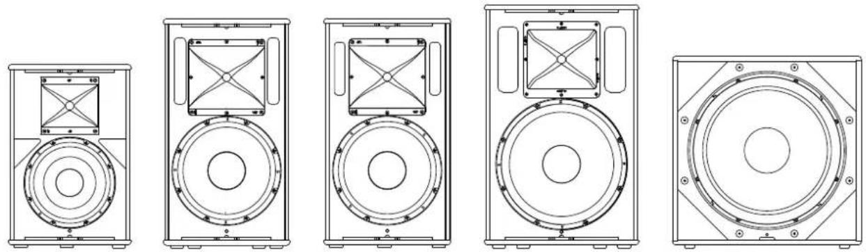
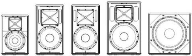
Five line drawings of speaker speakers arranged in a row, showing different speaker positions (no text or symbols present)L7 110 XA L7 112 FA L7 112 XA L7 115 FA L7 118 Sub A
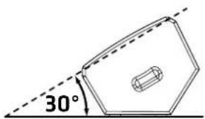
The LINEAR 7 series consists of four mid/high units and a subwoofer, the L7 110 XA, L7 112 XA, L7 112 FA, L7 115 FA and the L7 118 Sub A. The housings of the multifunctional L7 110 XA and L7 112 XA models are angled 30^ so you can also set them sideways for use monitors. The larger housings of the L7 112 FA and L7 115 FA fullrange models deliver more low-frequency sound pressure.
text_image
30°L7 110 XA / L7 112 XA
All XA and FA models are loaded with rotatable horns. The directivity of each cabinet's horn is optimized for its primary purpose – that is, the most frequently used application. The L7 110 XA cab sports a 10" woofer and a horn with a wide 80°x60° throw pattern to provide uniform near-fi eld coverage. L7 112 XA/FA cabs feature a 12" woofer and a horn with a medium 70°x50° throw pattern. The L7 115 FA cab comes with 15" woofer and a horn with a narrow 60°x40° long-throw pattern.
You need tools to rotate the horns, so they are not conducive to frequent adjustment. The idea is to optimize the throw pattern for the cabinet's primary application.
Tip: You do not have to rotate the horn when setting the cab on its side for use as a stage monitor. In fact, the upright speaker's narrower vertical throw pattern works great in the horizontal position. Its tightly focused directivity minimizes overlap with adjacent monitors and reduces the risk of feedback risk because you can aim the speaker more accurately.
4 Setting Up Speakers
4.1 The XA/FA Models
LINEAR 7 mid/high units may be stacked on subwoofers, mounted on speaker stands or poles, installed with wall brackets, or fl own with the proper rigging hardware.
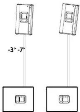
Setting Up with the DuoTilt 3/7
text_image
-3° -7°All mid/high units feature the HK Audio DuoTilt 3/7, a special mount for 35 mm speaker stands and poles offering two angles, -3° and -7°, to provide better coverage. The DuoTilt 3/7 is sited closer to the baffling to maintain the optimum center of gravity when the speaker is on a stand.
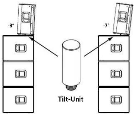
Setting Up with the Tilt Unit
text_image
-3° -7° Tilt-UnitHK Audio offers an optional Tilt Unit if you wish to tilt the mid/high units when they are stacked directly on subwoofers. It screws into the subwoofer's M20 mount just like a speaker pole. This lets you take advantage of the DuoTilt's -3° and -7° inclination angles in stacked setups with the Tilt Unit holding the mid/high units in place.
Caution! If you do not use the Tilt Unit to stack mid/high units, be sure to secure these cabinets in place, for example, with lashing straps.
General Info about Setting Up with Speaker Stands
Heads-up: Always make sure the speaker stand is on solid footing and be sure to observe the manufacturer's instructions as to its maximum load-bearing capacity.

Caution!
- Use only speaker stands that are stable enough to prevent accidental tipping. Ensure the speaker stand is designed to handle the cabinet's weight. Adjustable stands' highest setting must be limited to prevent the combination of speaker stand and speaker from tipping. This applies when setting the stand on a flat, horizontal surface.
- When setting up on an uneven or sloping surface, make sure the speaker stand's base is secured to prevent accidental tipping, either by attaching suitable weights to the base or taking other measures to secure the stand.
- The use of any other fixtures or fittings can result in instability that may result in injury.
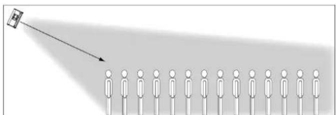
Rigging:
natural_image
Diagram showing a person emitting a beam of light from a target, with no text or symbols present.All XA and FA models can be flown by installing the AP-8 attachment and steel cables or chains to their rigging points, or by installing the proper truss brackets.
FA models provide heavy-duty 4x5 mm threaded inserts in the side-mounted shell grips serving to attach the HK Audio TB-45N or TB-45NQ (the Q stands for quick-release pins). XA models' wedge monitor-like angled panel does not accommodate a shell grip, so they come with reinforced 2x8 mm threaded mounting points that let you bolt on the HK Audio TB-28N truss bracket. Mounting instructions are enclosed with the truss brackets.
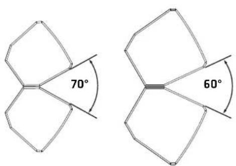
Clustering:
chemical
Two molecular structures with labeled bond angles of 70° and 60°L7 112 FA L7 115 FA
LINEAR 7 FA enclosures feature angled side panels for easy clustering.
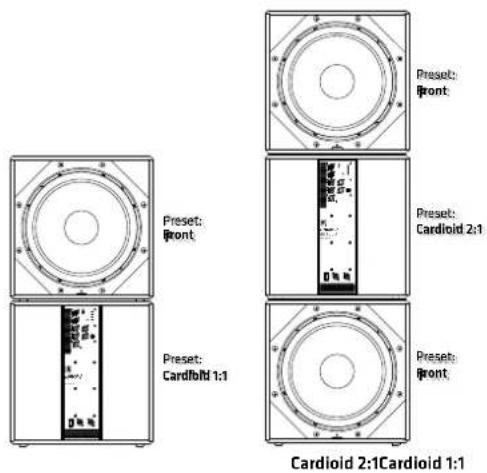
4.2 L7 118 Sub A
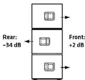
Deploy the L7 118 Sub A as you would any other direct radiating subwoofer. However, do not stack the bass bins when confi guring cardioid setups. Instead, place them side by side, maintaining a distance of at least one meter from walls. You have two cardioid setups to choose from - Cardioid 1:1 and Cardioid 2:1. The diagrams below show the front view from the audience's perspective.
text_image
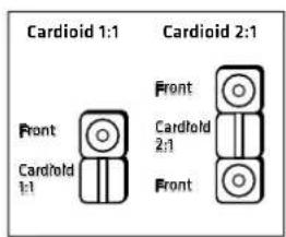
Preset: Front Preset: Cardiol 2:1 Preset: Cardiol 1:1 Cardiol 2:1Cardiol 1:1Select the proper preset for the given setup on the L7 118 Sub A's rear panel. See section 2, ⑧ Preset for more on this:
text_image
Cardioid 1:1 Cardioid 2:1 Front Cardioid 1:1 Front Cardioid 2:1 FrontBoth setups attenuate the rearward sound pressure level by up to 34 dB, and boost the forward SPL around 2 dB.
text_image
Rear: -34 dB Front: +2 dBWhen is it a good idea to go with a cardioid setup?
While speakers are able to throw midrange and high frequencies in directional patterns, low frequencies tend to radiate in all directions. Excessive bass levels can often be a problem on and behind the stage. And promoters are increasingly making demands to limit sound systems' low-end reach, for example, in festival tents at urban venues. Such demands for limiting low-range frequencies' range are best met with cardioid setups. With its hardware appointments and filter sets, the L7 118 Sub A provides a fast, easy way to configure effective cardioid setups.
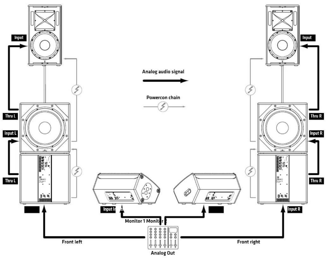
5 Example Systems
5.1 Setting Up a 2.1 Stereo System
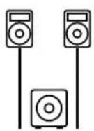
With the benefit of the L7 118 Sub A's onboard stereo preamp, you can easily set up a 2.1 system routing both the left and right channels into the L7 118 Sub A and then forwarding their signals to the mid/high units via its two Thru ports. The L7 110 XA's wide throw patterns are perfect for this application.
Presets:
| Mid/high units Low Cut |
| L7 118 Sub A Front |
For a balanced image, center the subwoofer between the two mid/high units.
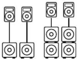
5.2 Setting Speakers on Poles
natural_image
Diagram showing two groups of speakers connected in a row, with no text or symbols present.If you wish to place mid/high units on speaker poles rather than stands, simply screw a pole with an M20 thread into the M20 pole mount on the L7 118 Sub A.
Presets:
| Mid/high units Low Cut |
| L7 118 Sub A Front |
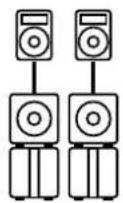
5.3 Stacking Speakers
Placing three L7 118 Sub As on top of one another creates a 1.65 m stack. You may place the mid/high units directly on the bass bins.
Presets:
| Mid/high units | Low Cut |
| L7 118 Sub A Front | |
5.4 Configuring a 1:1 Cardioid Setup
Use a speaker pole to set up 1:1 cardioid systems. Aim the bottom subwoofers to the rear.
Presets:
| Mid/high units Low Cut | |
| L7 118 Sub A - top Front | |
| L7 118 Sub A - bottom Cardioid 1:1 | |
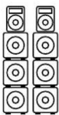
5.5 Configuring a 2:1 Cardioid Setup
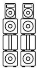
When setting up full cardioid stacks, aim the middle subwoofers to the rear.
Presets:
| Mid/high units Low Cut | |
| L7 118 Sub A - top Front | |
| L7 118 Sub A - center Cardioid 2:1 | |
| L7 118 Sub A - bottom Front |
You will find several example setups for your LINEAR 7 system starting on page 42.
6 Optional HK Audio Accessories
HK Audio offers rain covers for the FA/XA models. They also serve to protect the speakers in transit and splash-proof them during operation. Brackets are also available for mounting and flying speakers. Visit the LINEAR 7 product pages at www.hkaudio.com to learn more.
HK Audio offers a cover for the L7 118 Sub A to protect it in transit and a robust Rear Protection Plate (RPP) to splash-proof electronic components and guard against unauthorized handling in cardioid mode. The enclosure comes with mounting points for casters. Visit the LINEAR 7 product pages at www.hkaudio.com to learn more.
7 Technical Specifications
| Model L7 110 XA L7 112 XA L7 112 FA L7 115 FA L7 118 Sub A | |||||
| Max. SPL @ 10% THD 126 dB | half space(70 Hz - 12 kHz averaged) | 128 dB half space(70 Hz - 12 kHz averaged) | 128 dB half space(70 Hz - 12 kHz averaged) | 129 dB half space(70 Hz - 12 kHz averaged) | 129 dB half space(42 Hz - 100 Hz averaged) |
| Max. SPL peak @ 10%THD | 129 dB half space 131 dB half space | 131 dB half space 134 dB half space | 131 dB half space | ||
| Frequency response+/- 3 dB | 70 Hz - 19 kHz 67 Hz - 19 kHz 64 | Hz - 19 kHz 57 Hz - 19 kHz | 42 Hz - X-over | ||
| Frequency response-10 dB | 65 Hz - 19 kHz | 62 Hz - 19 kHz | 55 Hz - 20 kHz | 54 Hz - 19 kHz | 38 Hz - X-over |
| Power amp output (peakpower) | 2000 W | 2000 W | 2000 W | 2000 W | 2000 W |
| Amp type | Class D - biamped | Class D - biamped | Class D - biamped | Class D - biamped | Class D |
| Bass woofer | - | - | - | - | 1x 18", 4" voice coil |
| Low/Mid speaker | 1x 10", 2.5" voice coil | 1x 12", 2.5" voice coil | 1x 12", 2.5" voice coil | 1x 15", 3" voice coil | - |
| HF driver | 1", 1.4" voice coil | 1", 1.7" voice coil | 1", 1.7" voice coil | 1", 1.7" voice coil | - |
| Horn directivity | 80° x 60° CD horn, rotatable | 70° x 50° CD horn, rotatable | 70° x 50° CD horn, rotatable | 60° x 40° CD horn, rotatable | - |
| Active x-over frequency | 2 kHz FIR X-Overwith 60 dB/oct. | 1.6 kHz FIR X-Overwith 60 dB/oct. | 1.6 kHz FIR X-Overwith 60 dB/oct. | 1.5 kHz FIR X-Overwith 60 dB/oct. | - |
| Max. input level | +20 dBu | +20 dBu | +20 dBu | +20 dBu | +20 dBu |
| Analog ports | 1x XLR Combo In bal.,1x XLR Thru bal. | 1x XLR Combo In bal.,1x XLR Thru bal. | 1x XLR Combo In bal.,1x XLR Thru bal. | 1x XLR Combo In bal.,1x XLR Thru bal. | 2x XLR Combo In bal.,2x XLR Thru bal. |
| DSP Out | 1x XLR | 1x XLR | 1x XLR | 1x XLR | 1x XLR |
| Network port | Ethercon RJ45, 1x In, 1x Thru | Ethercon RJ45, 1x In, 1x Thru | Ethercon RJ45, 1x In, 1x Thru | Ethercon RJ45, 1x In, 1x Thru | Ethercon RJ45, 1x In, 1x Thru |
| Filter presets | Flat, Monitor, Low Cut, Remote | Flat, Monitor, Low Cut, Remote | Flat, Boost, Low Cut, Remote | Flat, Boost, Low Cut, Remote | Front, Cardioid 1:1, Cardioid 2:1,Remote |
| Remote software | HK Audio DSP CONTROL(Windows, Mac OS) | HK Audio DSP CONTROL(Windows, Mac OS) | HK Audio DSP CONTROL(Windows, Mac OS) | HK Audio DSP CONTROL(Windows, Mac OS) | HK Audio DSP CONTROL(Windows, Mac OS) |
| DSP functions | Fully parametric 10-band EQwith variable filter characteristics, High-Pass Filter, Low-Pass Filter, Polarity, Level, Delay,Limiter, Mute | Fully parametric 10-band EQwith variable filter characteristics, High-Pass Filter, Low-Pass Filter, Polarity, Level, Delay,Limiter, Mute | Fully parametric 10-band EQwith variable filter characteristics, High-Pass Filter, Low-Pass Filter, Polarity, Level, Delay,Limiter, Mute | Fully parametric 10-band EQ withvariable filter characteristics,High-Pass Filter, Low-Pass Filter,Polarity, Level, Delay, Limiter,Mute | Fully parametric 10-band EQ withvariable filter characteristics,High-Pass Filter, Low-Pass Filter,Polarity, Level, Delay, Limiter,Mute |
| Sampling rate | 96 kHz | 96 kHz | 96 kHz | 96 kHz | 96 kHz |
| System latency | less than 2.6 ms | less than 2.6 ms | less than 2.6 ms | less than 2.6 ms | less than 2.6 ms |
| Mains connector | 1x Powercon NAC3 In,100-240 V | 1x Powercon NAC3 In,100-240 V | 1x Powercon NAC3 In,100-240 V | 1x Powercon NAC3 In,100-240 V | 1x Powercon NAC3 In,1x Powercon NAC3 Thru, 100-240V |
| Power consumption | 1 A / 100-240 V nominalaccording to EN 62368-1 | 1 A / 100-240 V nominalaccording to EN 62368-1 | 1 A / 100-240 V nominal accor-ding to EN 62368-1 | 1 A / 100-240 V nominal accor-ding to EN 62368-1 | 1.9 A / 100-240 V nominalaccording to EN 62368-1 |
| Clustering angle | - | - | 70° | 60° | - |
| Angles up | 30° | 30° | - | - | - |
| Pole mount | DuoTilt 3"/7° | DuoTilt 3"/7° | DuoTilt 3"/7° | DuoTilt 3"/7° | 1x M20 |
| Suspension points | 5x M8 (AP-8) | 5x M8 (AP-8) | 4x M8 (AP-8) | 3x M8 (AP-8) | - |
| Grips | 2x SingleGrip | 1x MultiGrip, 1x SingleGrip | 2x MultiGrip | 2x MultiGrip | 2x MultiGrip |
| Housing | Hybrid (birch multiplex / MDF) | Hybrid (birch multiplex / MDF) | Hybrid (birch multiplex / MDF) | Hybrid (birch multiplex / MDF) | Birch multiplex |
| Front grille | 2 mm metal grille backed withblack acoustic foam | 2 mm metal grille backed withblack acoustic foam | 2 mm metal grille backed withblack acoustic foam | 2 mm metal grille backed withblack acoustic foam | 2 mm metal grille backed withblack acoustic foam |
| Finish | Black acrylic enamel | Black acrylic enamel | Black acrylic enamel | Black acrylic enamel | Black acrylic enamel |
| Dimensions (WxHxD) | 36 x 54 x 31 cm14-11/64 x 21-1/4 x 12-13/64" | 37 x 67 x 31 cm14-9/16 x 26-3/8 x 12-13/64" | 37 x 67 x 37 cm14-9/16 x 26-3/8 x 14-9/16" | 45 x 71 x 45 cm17-23/32 x 27-61/64 x 17-23/32" | 55 x 56 x 69 cm21-21/32 x 22-3/64 x 27-11/64" |
| Weight | 17 kg / 37.5 lbs | 21 kg / 46.3 lbs | 23 kg / 50.7 lbs | 32 kg / 70.5 lbs | 41 kg / 90.4 lbs |
natural_image
Diagram showing a person projecting a target from a camera toward a row of human figures (no text or symbols present)chemical
Two molecular structures with labeled bond angles of 70° and 60°L7 112 FA L7 115 FA
text_image
Rear: -34 dB Front: +2 dBnatural_image
Two identical line drawings of speakers arranged in a row, each with two speakers and one speaker connected to a base (no text or symbols)natural_image
Diagram showing a person projecting a target from a camera (no text or symbols present)text_image
Rear: -34 dB Front: +2 dBnatural_image
Diagram showing two groups of speakers with different speaker positions, connected by lines (no text or labels)natural_image
Five identical line drawings of a speaker tower with circular and rectangular panels, no text or symbols present.L7 110 XA L7 112 FA L7 112 XA L7 115 FA L7 118 Sub A
natural_image
Diagram showing a person projecting a target from a camera toward a row of human figures (no text or symbols present)chemical
Two molecular structures with labeled bond angles of 70° and 60°L7 112 FA L7 115 FA
text_image
Rear: -34 dB Front: +2 dBnatural_image
Diagram showing two groups of speakers with different speaker positions, connected by lines (no text or labels)natural_image
Diagram showing a person projecting a target from a camera toward a row of human figures (no text or symbols present)chemical
Two molecular structures with labeled bond angles of 70° and 60°L7 112 FA L7 115 FA
text_image
Rear: -34 dB Front: +2 dBnatural_image
Diagram showing two groups of speakers with different speaker positions, connected by lines (no text or symbols present)Use this option when rendering analog audio signals without the remote DSP CONTROL software.
flowchart
graph TD
    A["Speaker 1"] -->|Input| B["Powercon chain"]
    A -->|Input| C["Analog output"]
    A -->|Input| D["Analog output"]
    E["Speaker 2"] -->|Input| F["Powercon chain"]
    E -->|Input| G["Analog output"]
    E -->|Input| H["Analog output"]
    I["Thru L"] --> A
    J["Thru R"] --> K["Analog output"]
    L["Thru L"] --> A
    M["Thru R"] --> N["Analog output"]
    O["Thru L"] --> A
    P["Thru R"] --> Q["Analog output"]
    R["Thru L"] --> A
    S["Thru R"] --> T["Analog output"]
    U["Power Conchance"] --> V["Analog audio signal"]
    W["Monitor 1 Monitor"] --> X["Analog output"]
    Y["Power Conchance"] --> Z["Analog output"]
• Deutsch
1. Standard-Setup analog
für den Betrieb mit analogem Audio-Signal – ohne Remote-Software DSP CONTROL
• Français
1. Setup analogique standard
Pour l'utilisation avec un signal audio analogique - sans logiciel distant DSP CONTROL
• Italiano
1. Confi gurazione standard analogica
per l'utilizzo con segnale audio analogico - senza software remoto DSP CONTROL
- Español
1. Confi guración estándar analógica
para el funcionamiento con señal de audio analógica - sin software remoto DSP CONTROL
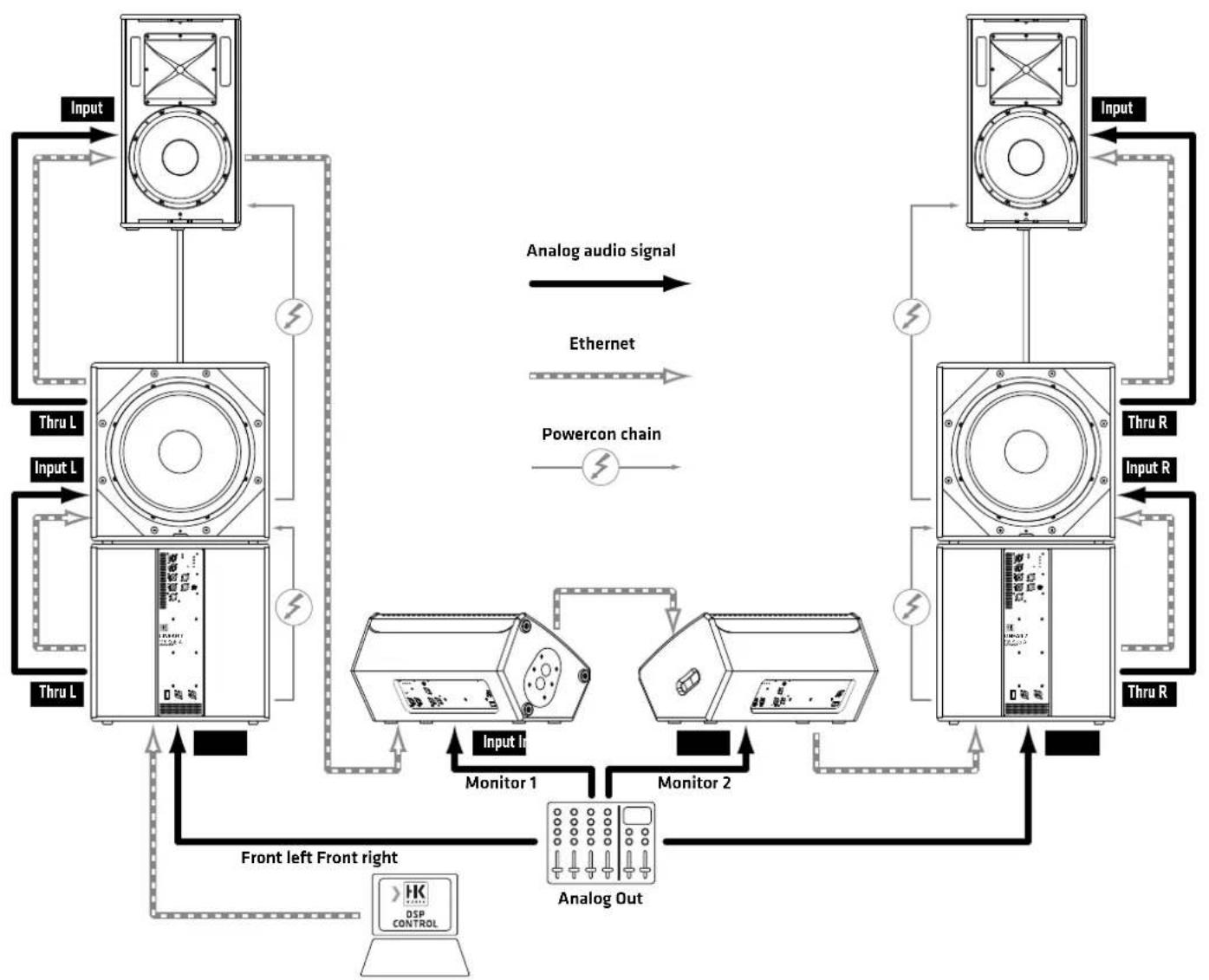
2. Daisy Chain 1
Use this option when rendering an analog audio signal with DSP CONTROL via Ethernet.
flowchart
graph TD
    A["Speaker 1"] -->|Input In| B["Monitor 1"]
    A -->|Input In| C["Monitor 2"]
    D["Speaker 2"] -->|Input In| E["Monitor 2"]
    D -->|Input In| F["Analog Out"]
    G["Speaker 3"] -->|Input In| H["Monitor 3"]
    G -->|Input In| I["Analog Out"]
    J["Speaker 4"] -->|Input In| K["Monitor 4"]
    J -->|Input In| L["Analog Out"]
    M["Speaker 5"] -->|Input In| N["Monitor 5"]
    M -->|Input In| O["Analog Out"]
    P["Speaker 6"] -->|Input In| Q["Monitor 6"]
    P -->|Input In| R["Analog Out"]
    S["Speaker 7"] -->|Input In| T["Monitor 7"]
    S -->|Input In| U["Analog Out"]
    V["Speaker 8"] -->|Input In| W["Monitor 8"]
    V -->|Input In| X["Analog Out"]
    Y["Speaker 9"] -->|Input In| Z["Monitor 9"]
    Y -->|Input In| AA["Analog Out"]
    AB["Speaker 10"] -->|Input In| AC["Monitor 10"]
    AB -->|Input In| AD["Analog Out"]
    AE["Speaker 11"] -->|Input In| AF["Monitor 11"]
    AE -->|Input In| AG["Analog Out"]
    AH["Speaker 12"] -->|Input In| AI["Monitor 12"]
    AH -->|Input In| AJ["Analog Out"]
    AK["Speaker 13"] -->|Input In| AL["Monitor 13"]
    AK -->|Input In| AM["Analog Out"]
    AN["Speaker 14"] -->|Input In| AO["Monitor 14"]
    AN -->|Input In| AP["Analog Out"]
    AQ["Speaker 15"] -->|Input In| AR["Monitor 15"]
    AQ -->|Input In| AS["Analog Out"]
    AT["Speaker 16"] -->|Input In| AU["Monitor 16"]
    AT -->|Input In| AV["Analog Out"]
    AW["Speaker 17"] -->|Input In| AX["Monitor 17"]
    AW -->|Input In| AY["Analog Out"]
    AZ["Speaker 18"] -->|Input In| BA["Monitor 18"]
    AZ -->|Input In| BB["Analog Out"]
    BC["Speaker 19"] -->|Input In| BD["Monitor 19"]
    BC -->|Input In| BE["Analog Out"]
    BF["Speaker 20"] -->|Input In| BG["Monitor 20"]
    BF -->|Input In| BH["Analog Out"]
    BI["Speaker 21"] -->|Input In| BJ["Monitor 21"]
    BI -->|Input In| BK["Analog Out"]
    BL["Speaker 22"] -->|Input In| BM["Monitor 22"]
    BL -->|Input In| BN["Analog Out"]
    BO["Speaker 23"] -->|Input In| BP["Monitor 23"]
    BO -->|Input In| BQ["Analog Out"]
    BR["Speaker 24"] -->|Input In| BS["Monitor 25"]
    BR -->|Input In| BT["Analog Out"]
    BU["Speaker 25"] -->|Input In| BV["Monitor 26"]
    BU -->|Input In| BW["Analog Out"]
    BX["Speaker 26"] -->|Input In| BY["Monitor 27"]
    BX -->|Input In| BZ["Analog Out"]
    CA["Speaker 27"] -->|Input In| CB["Monitor 28"]
    CA -->|Input In| CC["Analog Out"]
    CY["Speaker 28"] -->|Input In| CZ["Monitor 29"]
    CY -->|Input In| CC
    DA["Speaker 29"] -->|Input In| DB["Monitor 30"]
    DA -->|Input In| CC
    DC["Speaker 30"] -->|Input In| DD["Monitor 31"]
    DC -->|Input In| CC
• Deutsch
2. Daisy-Chain-Verkabelung 1
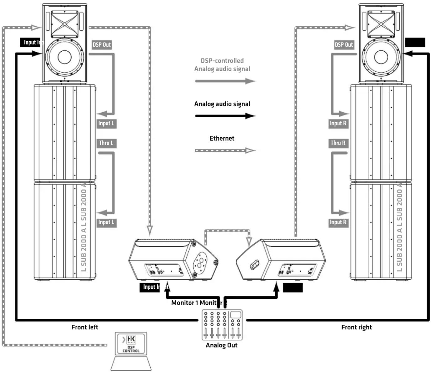
Use this option when integrating non-networkable powered speakers such as the L SUB 2000 in this example and rendering analog audio signals with DSP CONTROL via Ethernet. The DSP Out serves as an interface that forwards the digitally processed signal via an analog bus.
flowchart
graph TD
    A["Front left"] -->|Input L| B["Antenna"]
    B -->|DSP Out| C["Antenna"]
    C -->|DSP Out| D["Antenna"]
    D -->|DSP Out| E["Antenna"]
    E -->|DSP Out| F["Antenna"]
    F -->|DSP Out| G["Antenna"]
    G -->|DSP Out| H["Antenna"]
    H -->|DSP Out| I["Antenna"]
    I -->|DSP Out| J["Antenna"]
    J -->|DSP Out| K["Antenna"]
    K -->|DSP Out| L["Antenna"]
    L -->|DSP Out| M["Antenna"]
    M -->|DSP Out| N["Antenna"]
    N -->|DSP Out| O["Antenna"]
    O -->|DSP Out| P["Antenna"]
    P -->|DSP Out| Q["Antenna"]
    Q -->|DSP Out| R["Antenna"]
    R -->|DSP Out| S["Antenna"]
    S -->|DSP Out| T["Antenna"]
    T -->|DSP Out| U["Antenna"]
    U -->|DSP Out| V["Antenna"]
    V -->|DSP Out| W["Antenna"]
    W -->|DSP Out| X["Antenna"]
    X -->|DSP Out| Y["Antenna"]
    Y -->|DSP Out| Z["Antenna"]
    Z -->|DSP Out| AA["Antenna"]
    AA -->|DSP Out| AB["Antenna"]
    AB -->|DSP Out| AC["Antenna"]
    AC -->|DSP Out| AD["Antenna"]
    AD -->|DSP Out| AE["Antenna"]
    AE -->|DSP Out| AF["Antenna"]
    AF -->|DSP Out| AG["Antenna"]
    AG -->|DSP Out| AH["Antenna"]
    AH -->|DSP Out| AI["Antenna"]
    AI -->|DSP Out| AJ["Antenna"]
    AJ -->|DSP Out| AK["Antenna"]
    AK -->|DSP Out| AL["Antenna"]
    AL -->|DSP Out| AM["Antenna"]
    AM -->|DSP Out| AN["Antenna"]
    AN -->|DSP Out| AO["Antenna"]
    AO -->|DSP Out| AP["Antenna"]
    AP -->|DSP Out| AQ["Antenna"]
    AQ -->|DSP Out| AR["Antenna"]
    AR -->|DSP Out| AS["Antenna"]
    AS -->|DSP Out| AT["Antenna"]
    AT -->|DSP Out| AU["Antenna"]
    AU -->|DSP Out| AV["Antenna"]
    AV -->|DSP Out| AW["Antenna"]
    AW -->|DSP Out| AX["Antenna"]
    AX -->|DSP Out| AY["Antenna"]
    AY -->|DSP Out| AZ["Antenna"]
    AZ -->|DSP Out| BA["Antenna"]
    BA -->|DSP Out| BB["Antenna"]
    BB -->|DSP Out| BC["Antenna"]
    BC -->|DSP Out| BD["Antenna"]
    BD -->|DSP Out| BE["Antenna"]
    BE -->|DSP Out| BF["Antenna"]
    BF -->|DSP Out| BG["Antenna"]
    BG -->|DSP Out| BH["Antenna"]
    BH -->|DSP Out| BI["Antenna"]
    BI -->|DSP Out| BJ["Antenna"]
    BJ -->|DSP Out| BK["Antenna"]
    BK -->|DSP Out| BL["Antenna"]
    BL -->|DSP Out| BM["Antenna"]
    BM -->|DSP Out| BN["Antenna"]
    BN -->|DSP Out| BO["Antenna"]
    BO -->|DSP Out| BP["Antenna"]
    BP -->|DSP Out| BQ["Antenna"]
    BQ -->|DSP Out| BR["Antenna"]
    BR -->|DSP Out| BS["Antenna"]
    BS -->|DSP Out| BT["Antenna"]
    BT -->|DSP Out| BU["Antenna"]
    BU -->|DSP Out| BV["Antenna"]
    BV -->|DSP Out| BW["Antenna"]
    BW -->|DSP Out| BX["Antenna"]
    BX -->|DSP Out| BY["Antenna"]
    BY -->|DSP Out| BZ["Antenna"]
    BZ -->|DSP Out| CA["Antenna"]
    CA -->|DSP Out| CB["Antenna"]
    CB -->|DSP Out| CC["Antenna"]
    CC -->|DSP Out| DC["Antenna"]
    DC -->|DSP Out| DD["Antenna"]
    DD -->|DSP Out| BEQ["Antenna"]
    BEQ -->|DSP Out| BFQ["Antenna"]
    BFQ -->|DSP Out| BGQ["Antenna"]
    BGQ -->|DSP Out| BHQ["Antenna"]
    BHQ -->|DSP Out| BIQ["Antenna"]
    BIQ -->|DSP Out| BJQ
    BJQ -->|DSP Out| BKQ
    BKQ -->|DSP Out| BLQ
    BLQ -->|DSP Out| BMQ
    BMQ -->|DSP Out|
    BMQ -->|DSP Out|
    BMQ -->|DSP Out|
    BMQ -->|DSP Out|
    BMQ -->|DSP Out|
    BMQ -->|DSP Out|