
19557 - Desk Phone Vimar - Free user manual and instructions
Find the device manual for free 19557 Vimar in PDF.
| Product Type | Hands-free intercom for Due Fili system |
| Brand | Vimar |
| Model | 19557 |
| Number of modules | 3 modules |
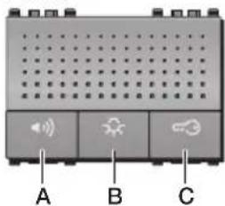
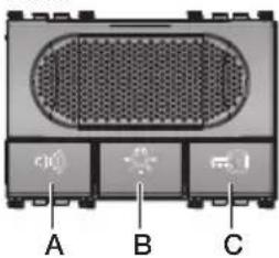
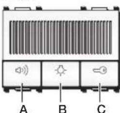
| Front keys | 3 keys: A (hands-free), B (auxiliary), C (door opener) |
| Maximum consumption (in call) | 150 mA |
| Normal consumption (standby) | 5 mA |
| Speaker | 16 Ω, 1 W, 500 Hz – 20 kHz |
| Microphone | 2 kΩ, 3 Vdc, 0.5 mA, 50 Hz – 16 kHz, S/N 58 dB |
| Operating temperature | +5 °C to +40 °C (indoor) |
| Power supply | Via Due Fili bus (12 Vdc) |
| Wiring type | Due Fili digital system |
| Main functions | Hands-free communication, door opener, staircase lighting, intercommunication, additional ringer |
| Settings | Audio volume and ringer volume via trimmers; primary and secondary encoding |
| Rear connectors | Bus line adaptation jumper, intercommunication button extension connector, PC programming connector |
| Encoding | Via configuration button, call plate, keypad, or PC with SaveProg software |
| Dimensions (approx.) | 3 standard modules (approx. 52 mm width) |
| Weight (approx.) | Approx. 120 g |
| Material | ABS plastic (estimate) |
| Available colors | White, black, silver (depending on Eikon, Arké, Plana series) |
| Maintenance and cleaning | Clean with a soft, dry cloth; do not use solvents |
| Certifications | Compliant with applicable standards; WEEE; REACH (lead traces) |
Frequently Asked Questions - 19557 Vimar
User questions about 19557 Vimar
0 question about this device. Answer the ones you know or ask your own.
Ask a new question about this device
Download the instructions for your Desk Phone in PDF format for free! Find your manual 19557 - Vimar and take your electronic device back in hand. On this page are published all the documents necessary for the use of your device. 19557 by Vimar.
USER MANUAL 19557 Vimar
ENGLISH Speakerphone Due Fili systems with door opening, stairlight and intercom functions - 3 modules 15
natural_image
Illustration of a finger pointing at the front panel of a portable electronic device with speaker icons and ports (no text or symbols)4 - ITALIANO

VIMAR
COLLEGAMENTI

Mors. Funzione
CONFORMITÀ NORMATIVA
Configuration (primary coding).... 19
Secondary coding (group calls) 20
Direct button function configuration 21
Additional ringtone.... 21
Bell push.... 22
Intercommunicating.... 22
Volume adjustment 26
Adapting the bus line.... 27
Installation rules.... 27
Conformity. 27
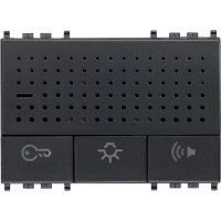
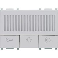
Speakerphone for Due Fili systems with door opening, stairlight and intercom functions - 3 modules.
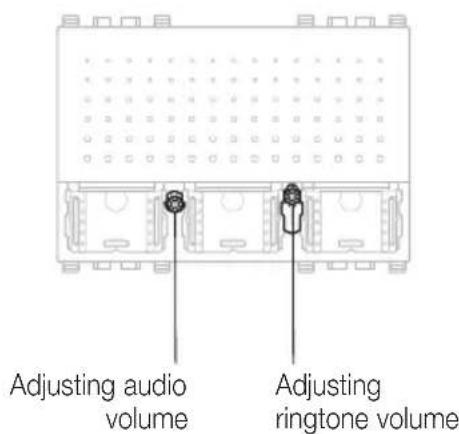
The speakerphone has to be installed exclusively in Due Fili system and allows communication with the outdoor (Due Fili entrance plates or call button 20577-19577-14577) and with Due Fili plates inside the building. There are three keys on the front of the unit. The first is for hands-free communication, the second for auxiliary use and the third is for unlocking the door. There are also two "trimmers" for adjusting speaker and ring tone volume and there is a button for encoding the unit. On the back of the unit (terminals side) there are: the BUSBAR bridge for making adjustments, the expansion connector for the intercom buttons and the connector for programming parameters by PC.
- Button A: Hands-free communication function (speak-listen).
- Button B: Auxiliary function.
- Button C: Unlock door function.

VIMAR
Eikon
Arké
Plana

VIMAR
CHARACTERISTICS
• Max absorption (in calls): 150 mA
• Normal absorption (on standby): 5 mA
• Speaker: 16 Ω, 1 W, 500 Hz - 20 kHz
- Microphone: 2 kΩ, 3 V d.c., 0.5 mA, 50 Hz - 16 kHz, S/N 58 dB
- Operating temperature: +5 °C - +40 °C (for indoor).
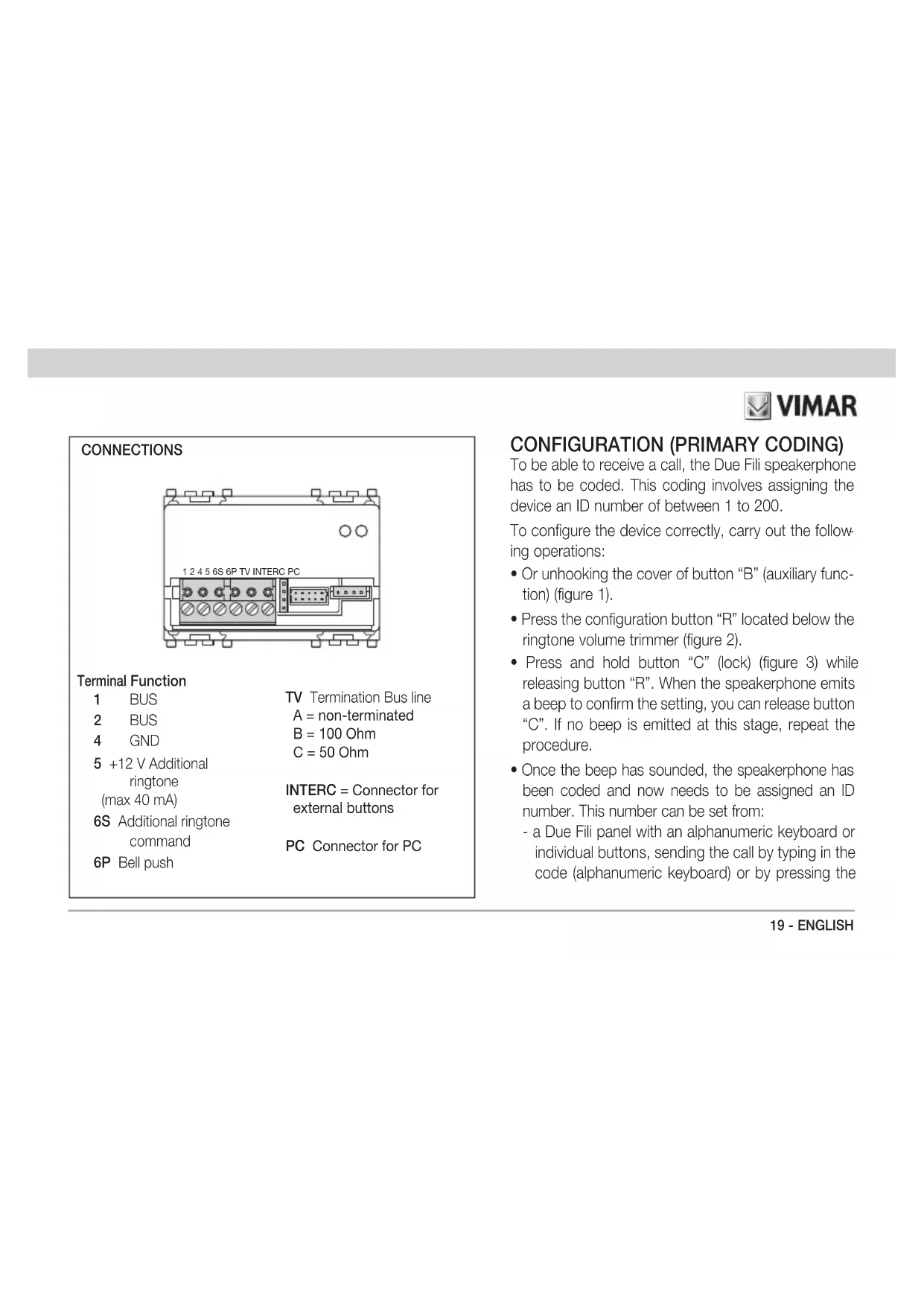
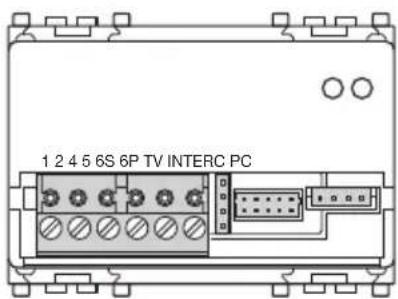
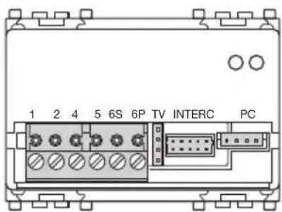
CONNECTIONS
See CONNECTION diagrams.
OPERATION
When a call is made from an outdoor plate (external plate or floor unit), the speakerphone rings; to speak with the caller press button "A" and keep it pressed for the entire conversation. For the best results, you are advised to speak from a distance of about 40 cms from the panel.
The auxiliary function is for managing external services e.g. turning on stairlights or triggering other tasks that can be sent by digital signals (AUX SERVICE 1 is the default setting). To activate the function press button "B".
The door unlocking function activates the separately wired electrically controlled lock mechanism that is operated from the LOCK button on the panel. To activate the function press button "C".
NOTE: For the meanings of digital commands, see the Due Fili technical documentation.
NOTE: The functions of buttons "B" and "C" (i.e. regarding digital signals sent to the bus) can be programmed with a personal computer and USB Interface and dedicated "SaveProg" software.

VIMAR
CONFIGURATION

VIMAR
CONNECTIONS
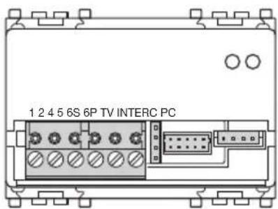
Terminal Function
| 1 | BUS | TV Termination Bus line |
| 2 | BUS | A = non-terminated |
| 4 | GND | B = 100 Ohm |
| 5 | +12 V Additional ringtone (max 40 mA) | C = 50 Ohm |
| 6S | Additional ringtone command | INTERC = Connector for external buttons |
| 6P | Bell push | PC Connector for PC |
CONFIGURATION (PRIMARY CODING)
To be able to receive a call, the Due Fili speakerphone has to be coded. This coding involves assigning the device an ID number of between 1 to 200.
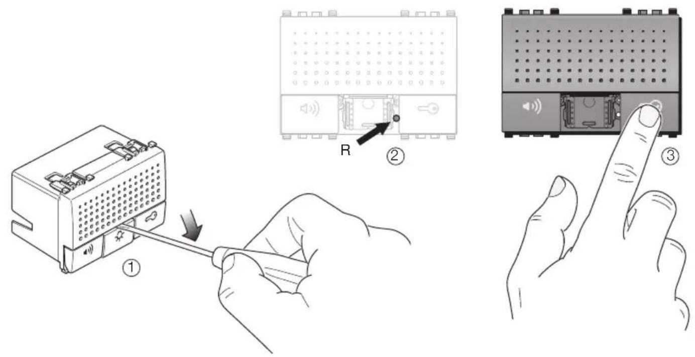
To configure the device correctly, carry out the following operations:
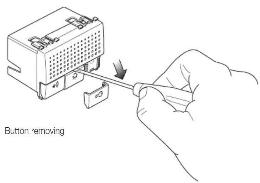
- Or unhooking the cover of button "B" (auxiliary function) (figure 1).
- Press the configuration button "R" located below the ringtone volume trimmer (figure 2).
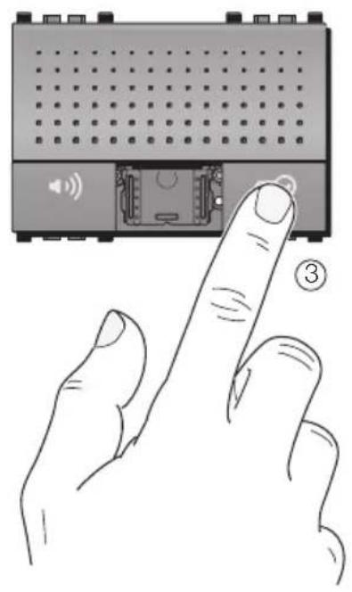
- Press and hold button "C" (lock) (figure 3) while releasing button "R". When the speakerphone emits a beep to confirm the setting, you can release button "C". If no beep is emitted at this stage, repeat the procedure.
- Once the beep has sounded, the speakerphone has been coded and now needs to be assigned an ID number. This number can be set from:
- a Due Fili panel with an alphanumeric keyboard or individual buttons, sending the call by typing in the code (alphanumeric keyboard) or by pressing the

VIMAR
button to be associated with the speakerphone (panel with buttons).
- a personal computer and USB Interface and dedicated "SaveProg" software.
As procedure differ for varying coding tools, see the technical documentation for instructions regarding coding the door entry system.
- When the code is sent, the entry phone beeps to confirm that coding has taken place; The code is then saved by the device and remains the same until a new configuration is input.
Even in the event of a power failure, the code remains as before.
SECONDARY CODING (Group Calls)
The same call can be sent to one or more door/video entry phones at the same time ("group call") in such a way that if the "master" is called, the call can be answered from all the door/video entry phones belonging to the group. The "master" is a directly coded door/video entry phone that is linked to a call from an external entrance plate.
f you want to program the video door entryphone as a secondary one of a certain master, press the configuration button "R" located below the ringtone volume trimmer (figure 2) then press and hold down the lock and auxiliary buttons "C" and "B" for at least 3 seconds until you hear a beep. You can now release buttons "C" and "B". From the plate, press the corresponding push button or enter the number of the master; the secondary will automatically acquire the ID code referring to the master.

VIMAR
DIRECT BUTTON FUNCTION CONFIGURATION
Buttons "B" and "C" can be configured at will by sending commands via the BUS that differ from the default settings (respectively AUX SERVICE 1 and LOCK); to configure buttons "B" and "C" without the programmer and/or personal computer, carry out the following operations:
- Unhook the cover of button "B" (auxiliary function) (figure 1).
- Press and hold button "R" located below the ringtone volume trimmer (figure 2).
- Press and hold the button you want to set ("B" or "C") and the hands free button "A" at the same time; release button "R". The door entryphone will emit a beep to confirm the setting and you can then release the buttons. If no beep is emitted at this stage, repeat the procedure.
- Once the beep has sounded, the door entryphone has been coded and now needs to receive the save command (sent from the PC USB interface and "SaveProg" software. For configuration details, refer to technical documentation.
IMPORTANT
During coding operations, take care not to assign the same code to more than one device. Needless to say, it is very important to keep a record of the codes assigned to the devices in the system (also useful in the event of expanding the system at some time in the future).
ADDITIONAL RINGTONE
To install additional call repeaters, use type '5' terminals (supply +12 V DC max 40 mA) and '6S' (GND command) to power a suitable external supporting relay.
BELL PUSH
An additional NO button can be installed to act as the bell push.
Use terminals '4' and '6P'.

VIMAR
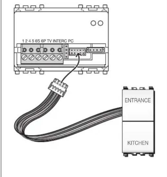
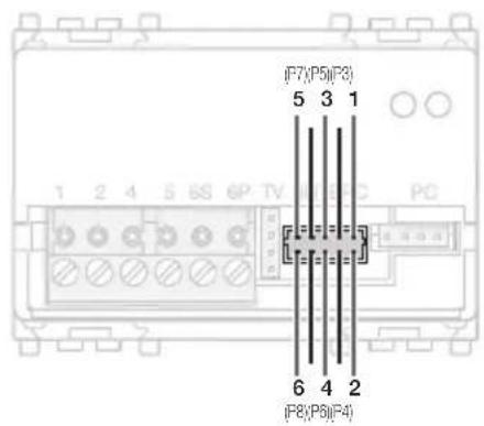
EXTERNAL BUTTON CONNECTIONS
INTERCOMMUNICATING
The entryphone can be enabled to receive and make intercommunicating audio calls. To make an intercommunicating call, an NO button (e.g. Art. 20066-19066-14066 dual button) needs to be wired with the enclosed connection cable and the entryphone needs to be configured using the PC USB interface and "SaveProg" software.
To configure the intercom buttons without the programmer and/or personal computer, carry out the following operations:
- Unhook the cover of button "B" (auxiliary function) (figure 1).
- Press the configuration button "R" located below the ring-tone volume trimmer (figure 2).
- Press and hold the button you want to set ("B" or "C") and the hands free button "A" at the same time. When the door entryphone emits a beep to confirm the setting, you can release the button. If no beep is emitted at this stage, repeat the procedure.

VIMAR
- Once the beep has sounded, the door entryphone has been coded and now needs to receive the ID number of the device to be called. This is done by pressing any key (e.g. lock or auxiliary function) on that device.
Button connection cable for intercom calls.
Up to 6 NO external door phone buttons can be installed with the intercom call expansion cable. The maximum number of intercom calls that can be handled is 6. Connect the auxiliary NO buttons as follows:
| Call wire (red, green or blue) | NO button contact. |
| Black wire NO button contact | return |
The expansion cable that comes with the speakerphone measures about 20 cm.
WARNING: Isolate any wires of the enclosed connection cable that are not used for the NO buttons to prevent contacts that will create false intercom calls.
The primary functions and entry phone options can also be set using the USB interface and the "SaveProg" software.

VIMAR
Diagram of buttons that can be configured with SaveProg:
| CORRESPONDENCE BETWEEN SaveProg AND ENTRY PHONE 20557 and button expansion module | ||
| SAVE PROG | Button | Function |
| P0 C LOCK MECHANISM | ||
| --- | ||
| P2 B AUX SERVICE 1 | ||
| P3 1 AUX SERVICE2 | ||
| P4 2 Free | ||
| P5 3 Free | ||
| P6 4 Free | ||
| P7 5 Free (F1 by default) | ||
| P8 6 Free (F2 by default) | ||
| CORRESPONDENCE BETWEEN SaveProg AND ENTRY PHONE 20557 and button expansion module | ||
| SAVE PROG | Button | Expansion cable |
| --- | ||
| --- | ||
| --- | ||
| P3 1 Red (high) | ||
| P4 2 Red | ||
| P5 3 Green (high) | ||
| P6 4 Green | ||
| P7 5 Blue (high) | ||
| P8 6 Blue | ||
EXTERNAL BUTTON CONNECTIONS

VIMAR
Example of configuring button functions using SaveProg software:
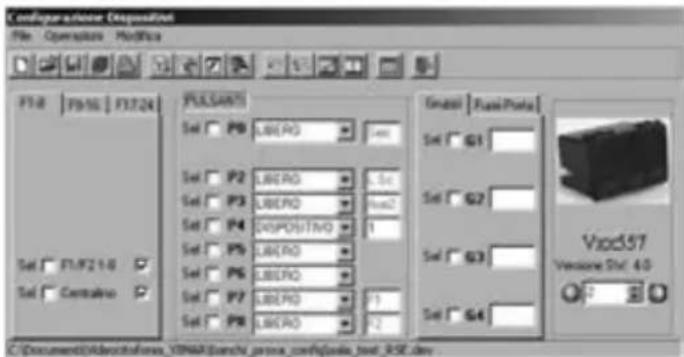
The setting of the DEVICE call (with ID=1) on button "P4" sends the intercom call to NO contact N° 2 to the door/video phone where the ID code = 1.
Deleting all settings
This procedure is recommended when you want to change the ID of a previously programmed door phone and do not want to save the device settings (restoring factory settings):
1) Press and hold button "R" located below the ringtone volume trimmer (figure 2)
2) Press and hold the buttons "A" and "B" together with button "R".
3) Release button "R" keeping buttons "A" and "B" pressed
4) After 2 seconds the entry phone give a long beep.
5) Release the buttons "A" and "B".
6) Press button "C" within 2 seconds.

VIMAR
VOLUME ADJUSTMENT

VIMAR
Reprogramming default values of single buttons
1) Press and hold button "R" located below the ringtone volume trimmer (figure 2)
2) Press and hold the button to be reprogrammed together with buttons "A" and "R".
3) Release the button "R", keeping the other two buttons pressed.
4) After 2 seconds the entry phone gives a beep.
5) Release the buttons and press the button again to restore the factory setting.
ADAPTING THE BUS LINE
In the event that the door entryphone is the last appliance connected to a branch of the BUS line, the line has to be terminated with a VT (Video Termination) jumper to ensure the best quality video signal (see figure alongside). Terminate the line and place a suitable jumper in position 'B' or 'C' and check the quality of the video signal on the nearest monitor. If the door entry phone is not the last appliance on the line, place the jumper in position 'A' (non-terminated line).
INSTALLATION RULES
Installation should be carried out observing current installation regulations for electrical systems in the country where the products are installed.
CONFORMITY
EMC directive. Standard EN 50486.
REACH (EU) Regulation no. 1907/2006 – Art.33. The product may contain traces of lead.

WEEE - User information
If the crossed-out bin symbol appears on the equipment or packaging, this means the product must not be included with other general waste at the end of its working life. The user must take the worn product to a sorted waste center, or return it to the retailer when purchasing a new one. Products for disposal can be consigned free of charge (without any new purchase obligation) to retailers with a sales area of at least 400 m ^2 , if they measure less than 25 cm. An efficient sorted waste collection for the environmentally friendly disposal of the used device, or its subsequent recycling, helps avoid the potential negative effects on the environment and people's health, and encourages the re-use and/or recycling of the construction materials.
$$ \frac{1}{2} = \frac{1}{3}\left(\frac{1}{4}\right)^{2} + \frac{1}{2}\left(\frac{1}{3}\right)^{2} + \dots +\frac{1}{2}\left(\frac{1}{3}\right)^{2} + \dots +\frac{1}{2}\left(\frac{1}{3}\right)^{2} + \dots +\frac{1}{2}\left(\frac{1}{3}\right)^{2} + \dots +\frac{1}{2}\left(\frac{1}{3}\right)^{2} + \dots +\frac{1.0}{2}\left(\frac{1}{3}\right)^{2} + \dots +\frac{1.0}{2}\left(\frac{1}{3}\right)^{2} + \dots +\frac{1.0}{2}\left(\frac{1}{3}\right)^{2} + \dots +\frac{1.0}{2}\left(\frac{1}{3}\right)^{2} + \dots +\dots +\frac{1.0}{2}\left(\frac{1}{3}\right)^{2} + \dots +\frac{1.0}{2}\left(\frac{1}{3}\right)^{2} + \dots +\frac{1.0}{2}\left(\frac{1}{3}\right)^{2} + \dots +\frac{1.0}{2}\left(\frac{1}{3}\right)^{\mathrm{max}} - \frac{1}{2} -\frac{1}{2}\left(\frac{1}{3}\right)^{\mathrm{max}} - \frac{1}{2}\left(\frac{1}{3}\right)^{\mathrm{max}} - \frac{1}{2}\left(\frac{1}{3}\right)^{\mathrm{max}} - \dots +\frac{1.0}{2}\left(\frac{1}{3}\right)^{\mathrm{max}} - \frac{1}{2}\left(\frac{1}{3}\right)^{\mathrm{max}} - \dots +\frac{1.0}{2}\left(\frac{1}{3}\right)^{\mathrm{max}} - \dots +\frac{1.0}{2}\left(\frac{1}{3}\right)^{\mathrm{max}} - \dots +\frac{1.0}{2}\left(\frac{1}{3}\right)^{\mathrm{max}} - \dots +\frac{1.0}{2}\left(\frac{1}{3}\right)^{\mathrm{n}} - \frac{\mathrm{n}}{\mathrm{n}} -\frac{\mathrm{n}}{\mathrm{n}} -\frac{\mathrm{n}}{\mathrm{n}} -\frac{\mathrm{n}}{\mathrm{n}} -\frac{\mathrm{n}}{\mathrm{n}} -\frac{\mathrm{n}}{\mathrm{n}} -\frac{\mathrm{n}}{\mathrm{n}} -\frac{\mathrm{n}}{\mathrm{n}} -\frac{\mathrm{n}}{\mathrm{n}} -\frac{\mathrm{n}}{\mathrm{n}} -\mathrm{n}\ $$

VIMAR
TABLES DES MATIERES
Description 30
Intercommunication.... 36
32 - FRANÇAIS

VIMAR
BRANCHEMENTS

Bornier Fonction
1 BUS
CONFORMITÉ AUX NORMES
Directive EMC. Norme EN 50486.

VIMAR
ANSCHLÜSSE
Klemme Funktion
1 BUS
INSTALLATIONSVORSCHRIFTEN

VIMAR
CONEXIONES

Borne Función
1 BUS

natural_image
Illustration of a finger pointing at the front panel of a portable electronic device with speaker icons and ports (no text or symbols)
VIMAR
ΣΥΝΔΕΣΕΙΣ
Επαφή Λειτουργία
1 BUS
2 BUS
4 GND
- VIMAR
- CONFORMITÀ NORMATIVA
- Speakerphone for Due Fili systems with door opening, stairlight and intercom functions - 3 modules.
- CHARACTERISTICS
- CONNECTIONS
- OPERATION
- CONFIGURATION (PRIMARY CODING)
- SECONDARY CODING (Group Calls)
- DIRECT BUTTON FUNCTION CONFIGURATION
- IMPORTANT
- ADDITIONAL RINGTONE
- BELL PUSH
- INTERCOMMUNICATING
- Button connection cable for intercom calls.
- Deleting all settings
- Reprogramming default values of single buttons
- ADAPTING THE BUS LINE
- INSTALLATION RULES
- CONFORMITY
- WEEE - User information
- TABLES DES MATIERES
- Bornier Fonction
- CONFORMITÉ AUX NORMES
- ANSCHLÜSSE
- Klemme Funktion
- INSTALLATIONSVORSCHRIFTEN
- Borne Función
- ΣΥΝΔΕΣΕΙΣ
- Επαφή Λειτουργία
Brand : Vimar
Model : 19557
Category : Desk Phone