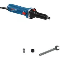
GWS 2400 P Professional - Coffee grinder BOSCH - Free user manual and instructions
Find the device manual for free GWS 2400 P Professional BOSCH in PDF.
User questions about GWS 2400 P Professional BOSCH
0 question about this device. Answer the ones you know or ask your own.
Ask a new question about this device
Download the instructions for your Coffee grinder in PDF format for free! Find your manual GWS 2400 P Professional - BOSCH and take your electronic device back in hand. On this page are published all the documents necessary for the use of your device. GWS 2400 P Professional by BOSCH.
USER MANUAL GWS 2400 P Professional BOSCH
natural_image
Three industrial angle milliosteps with visible blades and shafts, shown from different angles (no text or symbols)text_image
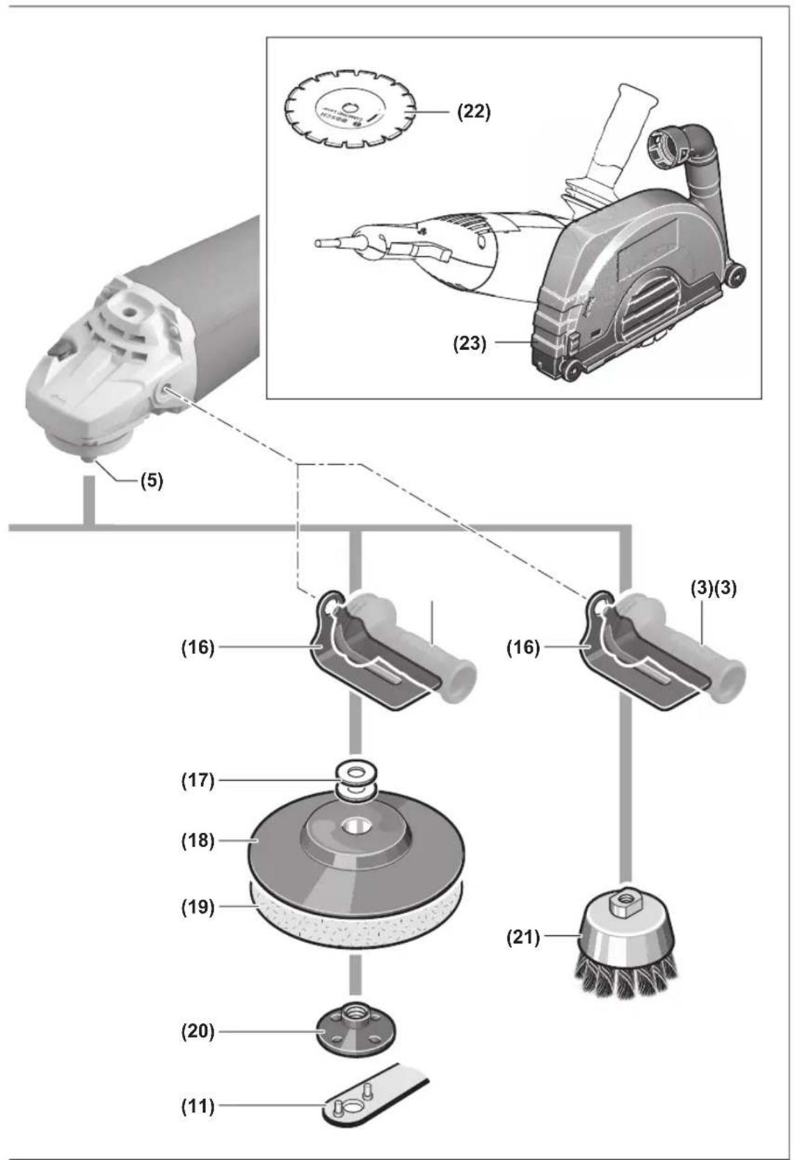
Technical diagram showing exploded and assembled views of a power tool with labeled parts including a grinding machine and various mechanical components.1609 92A 824 | (30.09.2022) Bosch Power Tools
text_image
(22) (23) (5) (16) (16) (3)(3) (17) (18) (19) (21) (20) (11)Deutsch
Sicherheitshinweise
natural_image
Technical illustration of a mechanical device with a cutting tool and gear mechanism, showing no text or symbols.natural_image
Illustration of a robotic arm with a rotating head and motion arrow (no text or symbols)www.bosch-pt.com/serviceaddresses
Entsorgung
General Power Tool Safety Warnings
WARNING
Read all safety warnings and all instructions. Failure to follow the
warnings and instructions may result in electric shock, fire and/or serious injury.
Save all warnings and instructions for future reference.
The term "power tool" in the warnings refers to your mains-operated (corded) power tool or battery-operated (cordless) power tool.
Work area safety
▶ Keep work area clean and well lit. Cluttered or dark areas invite accidents.
▶ Do not operate power tools in explosive atmospheres, such as in the presence of flammable liquids, gases or dust. Power tools create sparks which may ignite the dust or fumes.
▶ Keep children and bystanders away while operating a power tool. Distractions can cause you to lose control.
Electrical safety
▶ Power tool plugs must match the outlet. Never modify the plug in any way. Do not use any adapter plugs with earthed (grounded) power tools. Unmodified plugs and matching outlets will reduce risk of electric shock.
▶ Avoid body contact with earthed or grounded surfaces, such as pipes, radiators, ranges and refrigerators. There is an increased risk of electric shock if your body is earthed or grounded.
▶ Do not expose power tools to rain or wet conditions. Water entering a power tool will increase the risk of electric shock.
▶ Do not abuse the cord. Never use the cord for carrying, pulling or unplugging the power tool. Keep cord away from heat, oil, sharp edges or moving parts.
Damaged or entangled cords increase the risk of electric shock.
When operating a power tool outdoors, use an extension cord suitable for outdoor use. Use of a cord suitable for outdoor use reduces the risk of electric shock..
If operating a power tool in a damp location is unavoidable, use a residual current device (RCD) protected supply. Use of an RCD reduces the risk of electric shock.
16 | English
Personal safety
▶ Stay alert, watch what you are doing and use common sense when operating a power tool. Do not use a power tool while you are tired or under the influence of drugs, alcohol or medication. A moment of inattention while operating power tools may result in serious personal injury.
▶ Use personal protective equipment. Always wear eye protection. Protective equipment such as dust mask, non-skid safety shoes, hard hat, or hearing protection used for appropriate conditions will reduce personal injuries.
▶ Prevent unintentional starting. Ensure the switch is in the off-position before connecting to power source and/or battery pack, picking up or carrying the tool. Carrying power tools with your finger on the switch or energising power tools that have the switch on invites accidents.
Remove any adjusting key or wrench before turning the power tool on. A wrench or a key left attached to a rotating part of the power tool may result in personal injury.
▶ Do not overreach. Keep proper footing and balance at all times. This enables better control of the power tool in unexpected situations.
▶ Dress properly. Do not wear loose clothing or jewellery. Keep your hair, clothing and gloves away from moving parts. Loose clothes, jewellery or long hair can be caught in moving parts.
▶ If devices are provided for the connection of dust extraction and collection facilities, ensure these are connected and properly used. Use of dust collection can reduce dust-related hazards.
Power tool use and care
▶ Do not force the power tool. Use the correct power tool for your application. The correct power tool will do the job better and safer at the rate for which it was designed.
▶ Do not use the power tool if the switch does not turn it on and off. Any power tool that cannot be controlled with the switch is dangerous and must be repaired.
▶ Disconnect the plug from the power source and/or the battery pack from the power tool before making any adjustments, changing accessories, or storing power tools. Such preventive safety measures reduce the risk of starting the power tool accidentally.
▶ Store idle power tools out of the reach of children and do not allow persons unfamiliar with the power tool or these instructions to operate the power tool. Power tools are dangerous in the hands of untrained users.
- Maintain power tools. Check for misalignment or binding of moving parts, breakage of parts and any other condition that may affect the power tool's operation. If damaged, have the power tool repaired before use. Many accidents are caused by poorly maintained power tools.
▶ Keep cutting tools sharp and clean. Properly maintained cutting tools with sharp cutting edges are less likely to bind and are easier to control.
▶ Use the power tool, accessories and tool bits etc. in accordance with these instructions, taking into account the working conditions and the work to be performed. Use of the power tool for operations different from those intended could result in a hazardous situation.
Service
▶ Have your power tool serviced by a qualified repair person using only identical replacement parts. This will ensure that the safety of the power tool is maintained.
Safety Warnings for Angle Grinder
Safety Warnings common for Grinding, Sanding, Wire Brushing or Abrasive Cutting Off operations
This power tool is intended to function as a grinder, sander, wire brush or cut-off tool. Read all safety warnings, instructions, illustrations and specifications provided with this power tool. Failure to follow all instructions listed below may result in electric shock, fire and/or serious injury.
▶ Operations such as polishing are not recommended to be performed with this power tool. Operations for which the power tool was not designed may create a hazard and cause personal injury.
▶ Do not use accessories which are not specifically designed and recommended by the tool manufacturer. Just because the accessory can be attached to your power tool, it does not assure safe operation.
The rated speed of the accessory must be at least equal to the maximum speed marked on the power tool. Accessories running faster than their rated speed can break and fly apart.
The outside diameter and the thickness of your accessory must be within the capacity rating of your power tool. Incorrectly sized accessories cannot be adequately guarded or controlled.
Threaded mounting of accessories must match the grinder spindle thread. For accessories mounted by flanges, the arbour hole of the accessory must fit the locating diameter of the flange. Accessories that do not match the mounting hardware of the power tool will run out of balance, vibrate excessively and may cause loss of control.
▶ Do not use a damaged accessory. Before each use inspect the accessory such as abrasive wheels for chips and cracks, backing pad for cracks, tear or excess wear, wire brush for loose or cracked wires. If power tool or accessory is dropped, inspect for damage or install an undamaged accessory. After inspecting and installing an accessory, position yourself and bystanders away from the plane of the rotating accessory and run the power tool at maximum no load speed for one minute. Damaged accessories will normally break apart during this test time.
▶ Wear personal protective equipment. Depending on application, use face shield, safety goggles or safety glasses. As appropriate, wear dust mask, hearing protectors, gloves and workshop apron capable of stopping small abrasive or workpiece fragments. The eye protection must be capable of stopping flying debris generated by various operations. The dust mask or respirator must be capable of filtrating particles generated by your operation. Prolonged exposure to high intensity noise may cause hearing loss.
▶ Keep bystanders a safe distance away from work area. Anyone entering the work area must wear personal protective equipment. Fragments of workpiece or of a broken accessory may fly away and cause injury beyond immediate area of operation.
▶ Hold the power tool by insulated gripping surfaces only, when performing an operation where the cutting accessory may contact hidden wiring or its own cord. Cutting accessory contacting a "live" wire may make exposed metal parts of the power tool "live" and could give the operator an electric shock.
▶ Position the cord clear of the spinning accessory. If you lose control, the cord may be cut or snagged and your hand or arm may be pulled into the spinning accessory.
▶ Never lay the power tool down until the accessory has come to a complete stop. The spinning accessory may grab the surface and pull the power tool out of your control.
▶ Do not run the power tool while carrying it at your side. Accidental contact with the spinning accessory could snag your clothing, pulling the accessory into your body.
Regularly clean the power tool's air vents. The motor's fan will draw the dust inside the housing and excessive accumulation of powdered metal may cause electrical hazards.
▶ Do not operate the power tool near flammable materials. Sparks could ignite these materials.
▶ Do not use accessories that require liquid coolants. Using water or other liquid coolants may result in electrocution or shock.
Kickback and Related Warnings
Kickback is a sudden reaction to a pinched or snagged rotating wheel, backing pad, brush or any other accessory. Pinching or snagging causes rapid stalling of the rotating accessory which in turn causes the uncontrolled power tool to be forced in the direction opposite of the accessory's rotation at the point of the binding.
For example, if an abrasive wheel is snagged or pinched by the workpiece, the edge of the wheel that is entering into the pinch point can dig into the surface of the material causing the wheel to climb out or kick out. The wheel may either jump toward or away from the operator, depending on direction of the wheel's movement at the point of pinching. Abrasive wheels may also break under these conditions.
Kickback is the result of power tool misuse and/or incorrect operating procedures or conditions and can be avoided by taking proper precautions as given below.
Maintain a firm grip on the power tool and position your body and arm to allow you to resist kickback forces. Always use auxiliary handle, if provided, for maximum control over kickback or torque reaction during start-up. The operator can control torque reactions or kickback forces, if proper precautions are taken.
▶ Never place your hand near the rotating accessory.
Accessory may kickback over your hand.
Do not position your body in the area where power tool will move if kickback occurs. Kickback will propel the tool in direction opposite to the wheel's movement at the point of snagging.
▶ Use special care when working corners, sharp edges etc. Avoid bouncing and snagging the accessory.
Corners, sharp edges or bouncing have a tendency to snag the rotating accessory and cause loss of control or kickback.
▶ Do not attach a saw chain woodcarving blade or toothed saw blade. Such blades create frequent kickback and loss of control.
Safety Warnings specific for Grinding and Abrasive Cutting-Off operations
▶ Use only wheel types that are recommended for your power tool and the specific guard designed for the selected wheel. Wheels for which the power tool was not designed cannot be adequately guarded and are unsafe.
The grinding surface of centre depressed wheels must be mounted below the plane of the guard lip. An improperly mounted wheel that projects through the plane of the guard lip cannot be adequately protected.
The guard must be securely attached to the power tool and positioned for maximum safety, so the least amount of wheel is exposed towards the operator. The guard helps to protect operator from broken wheel fragments, accidental contact with wheel and sparks that could ignite clothing.
▶ Wheels must be used only for recommended applications. For example: do not grind with the side of cut-off wheel. Abrasive cut-off wheels are intended for peripheral grinding, side forces applied to these wheels may cause them to shatter.
▶ Always use undamaged wheel flanges that are of correct size and shape for your selected wheel. Proper wheel flanges support the wheel thus reducing the possibility of wheel breakage. Flanges for cut-off wheels may be different from grinding wheel flanges.
▶ Do not use worn down wheels from larger power tools. Wheel intended for larger power tool is not suitable for the higher speed of a smaller tool and may burst.
Additional Safety Warnings specific for Abrasive Cutting Off operations
▶ Do not "jam" the cut-off wheel or apply excessive pressure. Do not attempt to make an excessive depth of cut. Overstressing the wheel increases the loading
18 | English
and susceptibility to twisting or binding of the wheel in the cut and the possibility of kickback or wheel breakage.
▶ Do not position your body in line with and behind the rotating wheel. When the wheel, at the point of operation, is moving away from your body, the possible kick-back may propel the spinning wheel and the power tool directly at you.
When wheel is binding or when interrupting a cut for any reason, switch off the power tool and hold the power tool motionless until the wheel comes to a complete stop. Never attempt to remove the cut-off wheel from the cut while the wheel is in motion otherwise kickback may occur. Investigate and take corrective action to eliminate the cause of wheel binding.
▶ Do not restart the cutting operation in the workpiece. Let the wheel reach full speed and carefully re-enter the cut. The wheel may bind, walk up or kickback if the power tool is restarted in the workpiece.
▶ Support panels or any oversized workpiece to minimize the risk of wheel pinching and kickback. Large workpieces tend to sag under their own weight. Supports must be placed under the workpiece near the line of cut and near the edge of the workpiece on both sides of the wheel.
▶ Use extra caution when making a “pocket cut” into existing walls or other blind areas. The protruding wheel may cut gas or water pipes, electrical wiring or objects that can cause kickback.
Safety Warnings specific for Sanding operations
▶ Do not use excessively oversized sanding disc paper. Follow manufacturers recommendations, when selecting sanding paper. Larger sanding paper extending beyond the sanding pad presents a laceration hazard and may cause snagging, tearing of the disc, or kickback.
Safety Warnings specific for Wire Brushing operations
▶ Be aware that wire bristles are thrown by the brush even during ordinary operation. Do not overstress the wires by applying excessive load to the brush The wire bristles can easily penetrate light clothing and/or skin.
If the use of a guard is recommended for wire brushing, do not allow any interference of the wire wheel or brush with the guard. Wire wheel or brush may expand in diameter due to work load and centrifugal forces.
Additional safety information

Wear safety goggles.
▶ Use suitable detectors to determine if utility lines are hidden in the work area or call the local utility company for assistance. Contact with electric lines can lead to fire and electric shock. Damaging a gas line can lead to explosion. Penetrating a water line causes property damage or may cause an electric shock.
▶ Do not touch grinding and cutting discs until they have cooled down. The discs can become very hot while working.
▶ Release the On/Off switch and set it to the off position when the power supply is interrupted, e. g., in case of a power failure or when the mains plug is pulled. This prevents uncontrolled restarting.
- Secure the workpiece. A workpiece clamped with clamping devices or in a vice is held more secure than by hand.
Products sold in GB only:
Your product is fitted with an BS 1363/A approved electric plug with internal fuse (ASTA approved to BS 1362).
If the plug is not suitable for your socket outlets, it should be cut off and an appropriate plug fitted in its place by an authorised customer service agent. The replacement plug should have the same fuse rating as the original plug.
The severed plug must be disposed of to avoid a possible shock hazard and should never be inserted into a mains socket elsewhere.

Hold the power tool firmly with both hands and make sure you have a stable footing. The power tool can be more securely guided with both hands.
Product Description and Specifications

Read all the safety and general instructions.
Failure to observe the safety and general instructions may result in electric shock, fire and/or serious injury.
Please observe the illustrations at the beginning of this operating manual.
Intended use
The power tool is intended for cutting, roughing and brushing metal and stone materials without the use of water.
A separate protective guard for cutting must be used when cutting with bonded abrasives.
Sufficient dust extraction must be provided when cutting stone.
With approved abrasive tools, the power tool can be used for sanding with sanding discs.
Product features
The numbering of the product features refers to the diagram of the power tool on the graphics page.
(1) Spindle lock button
(2) On/off switch
(3) Auxiliary handle (insulated gripping surface)
(4) Handle (insulated gripping surface)
(5) Grinding spindle
(6) Protective guard for grinding
(7) Locking screw for protective guard
(8) Mounting flange with O-ring
(9) Grinding disc ^a)
(10) Clamping nut
(11) Two-pin spanner for clamping nut
(12) Quick-clamping nut SDS-clic ^a)
(13) Carbide grinding head ^a)
(14) Protective guard for cutting ^a)
(15) Cutting disc ^a
(16) Hand guard ^a)
(17) Spacer discs ^a)
(18) Rubber sanding pad ^a)
(19) Abrasive disc ^a)
(20) Round nut ^a)
(21) Cup brush ^a)
(22) Diamond cutting disc ^a)
(23) Extraction guard for cutting with cutting guides ^a)
a) Accessories shown or described are not included with the product as standard. You can find the complete selection of accessories in our accessories range.
Technical data
| Article number | 3 601 HF2 0.. 3 601 HF2 1.. 3 601 HF4 0.. 3 601 HF4 1.. 3 601 HF4 2.. 3 601 HF4 3.. | |||||
| Rated power input W 2000 2000 2200 2200 2400 2400 | ||||||
| Rated speed min | -1 | 6500 | 6500 | 6500 | 6500 | 6500 |
| Max. grinding disc diameter | mm | 230 | 230 | 230 | 230 | 230 |
| Grinding spindle thread | M14 | M14 | M14 | M14 | M14 | |
| Max. thread length of grinding spindle | mm | 25 | 25 | 25 | 25 | |
| Restart protection ● - ● - ● - | ||||||
| Soft start ● - ● - ● - | ||||||
| Weight according to EPTA-Procedure 01:2014 | ||||||
| - with low-vibration auxiliary handle | kg | 5.2 | 5.1 | 5.5 | 5.4 | 5.5 |
| - with standard auxiliary handle | kg | 5.1 | 5.0 | 5.4 | 5.3 | 5.4 |
| Protection class | ☐/II | ☐/II | ☐/II | ☐/II | ||
The specifications apply to a rated voltage [U] of 230 V. These specifications may vary at different voltages and in country-specific models.
Notes on mains connection requirements for GWS 2000 P/GWS 2200 P/GWS 2400 P:
The appliance meets IEC 61000-3-11 requirements and is subject to conditional connection. The appliance can lead to occasional voltage fluctuations under unfavorable power conditions. The impedance of this appliance is set as Z_actual = 0.18 . The user must make sure, that the connection point, with the impedance Z_max , on which the appliance shall be plugged in meets the impedance requirement: Z_actual ≥ Z_max . If Z_max is unknown, determine Z_max in consultation with the network supplier or supply authority.
Noise/Vibration Information
Noise emission values determined according to EN 60745-2-3.
Typically the A-weighted noise level of the power tool are: 97 dB(A); sound power level 108 dB(A). Uncertainty K = 3 dB.
Wear hearing protection!
Vibration total values a_n (triax vector sum) and uncertainty K determined according to EN 60745-2-3:
Surface grinding (roughing):
$$ a _ {n} = 7. 5 \mathrm{m} / \mathrm{s} ^ {2}, K = 1. 5 \mathrm{m} / \mathrm{s} ^ {2}, $$
Disc sanding:
$$ a _ {n} = 4. 5 \mathrm{m} / \mathrm{s} ^ {2}, K = 1. 5 \mathrm{m} / \mathrm{s} ^ {2}. $$
The vibration level given in these instructions has been measured in accordance with a standardised measuring procedure and may be used to compare power tools. It can also be used for a preliminary estimation of exposure to vibration.
The stated vibration level applies to the main applications of the power tool. However, if the power tool is used for different applications, with different application tools or poorly maintained, the vibration level may differ. This can significantly increase the exposure to vibration over the total working period.
20 | English
To estimate the exposure to vibration accurately, the times when the tool is switched off or when it is running but not actually being used should also be taken into account. This can significantly reduce the exposure to vibration over the total working period.
Implement additional safety measures to protect the operator from the effects of vibration, such as servicing the power tool and application tools, keeping the hands warm, and organising workflows correctly.
Fitting
Fitting Protective Equipment
▶ Pull the plug out of the socket before carrying out any work on the power tool.
Note: If the grinding disc breaks during operation or the holding fixtures on the protective guard/power tool become damaged, the power tool must be sent to the after-sales service immediately; see the "After-Sales Service and Application Service" section for addresses.
Protective guard for grinding
Place the protective guard (6) on the spindle collar. Adjust the position of the protective guard (6) to the requirements of the operation and lock the protective guard (6) with the locking screw (7).
▶ Adjust the protective guard (6) such that sparking in the direction of the operator is prevented.
Protective guard for cutting
▶ Always use the protective guard for cutting (14) when cutting with bonded abrasives.
▶ Provide sufficient dust extraction when cutting stone.
The protective guard for cutting (14) is fitted in the same way as the protective guard for grinding (6).
Extraction guard for cutting with a guide block
Observe the operating instructions of the extraction guard when fitting the extraction guard for cutting with a cutting guide (23).
Side handle
▶ Do not operate your power tool without the side handle (3).
Screw the side handle (3) on the left or right of the machine head depending on how your are working.
Hand guard
▶ Always fit the hand guard (16) when working with the rubber sanding plate (18) or with the cup brush/disc brush/flap disc.
Attach the hand guard (16) to the side handle (3).
Fitting the Abrasive Tools
▶ Pull the plug out of the socket before carrying out any work on the power tool.
▶ Do not touch grinding and cutting discs until they have cooled down. The discs can become very hot while working.
Clean the grinding spindle (5) and all the parts to be fitted.
Lock the grinding spindle with the spindle lock button (1) before clamping and releasing the abrasive tools.
▶ Do not press the spindle lock button while the grinding spindle is moving. The power tool may become damaged if you do this.
Grinding/cutting disc
Pay attention to the dimensions of the abrasive tools. The diameter of the hole must match that of the mounting flange. Do not use an adapter or reducer.
When using diamond cutting discs, ensure that the arrow indicating the direction of rotation on the diamond cutting disc matches the direction of rotation of the power tool (see the direction of rotation arrow on the machine head).
See the graphics page for assembly instructions.
To fasten the grinding/cutting disc, screw on the clamping nut (10) and tighten with the two-hole spanner. (see "Quick-clamping nut" size 2.6:15
▶ After fitting the abrasive tool, check that the abrasive tool is fitted correctly and can turn freely before switching on the power tool. Make sure that the abrasive tool does not brush against the protective guard or other parts.
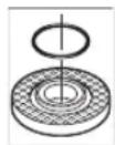
A plastic part (O-ring) is fitted around the cent-ring collar in the mounting flange (8). If the O-ring is missing or damaged, the mounting flange (8) must be replaced before operation can resume.
Flap disc
▶ Always fit the hand guard (16) when working with the flap disc.
Rubber sanding pad
▶ Always fit the hand guard (16) when working with the rubber sanding pad (18).
See the graphics page for fitting instructions.
Before fitting the rubber sanding pad (18), place the two spacer discs (17) on the grinding spindle (5).
Screw on the round nut (20) and tighten with the two-pin spanner.
Cup brush/disc brush
▶ Always fit the hand guard (16) when working with the cup brush or disc brush.
See the graphics page for fitting instructions.
The cup brush/disc brush must be screwed onto the grinding spindle until it rests firmly against the grinding spindle flange at the end of the grinding spindle thread. Tighten the cup brush/disc brush with an open-ended spanner.
Quick-clamping nut SDS-clic
To change the abrasive tool easily without having to use any additional tools, you can use the quick-clamping nut (12) instead of the clamping nut (10).
▶ The quick-clamping nut (12) may be used only for grinding or cutting discs or disc brushes with hole diameter 22.2 mm.
Only use quick-clamping nuts (12) that are in good working order and not damaged.
When screwing on, make sure that the printed side of the quick-clamping nut (12) is not facing the grinding disc; the arrow must be pointing towards the index mark (24).
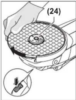
text_image
(24)Press the spindle lock button (1) to lock the grinding spindle. To tighten the quick-clamping nut, turn the grinding disc firmly clockwise.
natural_image
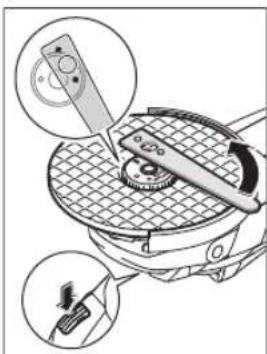
Technical illustration of a mechanical device with a cutting tool and gear mechanism, showing no text or symbols.If the quick-clamping nut has been attached correctly and is not damaged, you can loosen it by hand by turning the knurled ring anticlockwise. If the quick-clamping nut is stuck, do not attempt to loosen it with pliers – always use the two-pin spanner. Position the two-pin spanner as shown in the figure.
Approved abrasive tools
You can use all the abrasive tools mentioned in these operating instructions.
The permissible speed [min^-1] or the circumferential speed [m/s] of the abrasive tools used must at least match the values given in the table.
It is therefore important to observe the permissible rotational/circumferential speed on the label of the abrasive tool.

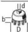
text_image
Max. [mm] [mm] D b d [min -1] [m/s]
230 8 22.2 6500 80

text_image
Max. [mm] [mm] D b d [min -1] [m/s]
180--650080

100 30 M14 8500 45
Dust/Chip Extraction
The dust from materials such as lead paint, some types of wood, minerals and metal can be harmful to human health. Touching or breathing in this dust can trigger allergic reactions and/or cause respiratory illnesses in the user or in people in the near vicinity.
Certain dusts, such as oak or beech dust, are classified as carcinogenic, especially in conjunction with wood treatment additives (chromate, wood preservative). Materials containing asbestos may only be machined by specialists.
- Use a dust extraction system that is suitable for the material wherever possible.
- Provide good ventilation at the workplace.
- It is advisable to wear a P2 filter class breathing mask.
The regulations on the material being machined that apply in the country of use must be observed. - Avoid dust accumulation at the workplace. Dust can easily ignite.
Operation
Start-Up
▶ Pay attention to the mains voltage. The voltage of the power source must match the voltage specified on the rating plate of the power tool. Power tools marked with 230 V can also be operated with 220 V.
▶ Products that are only sold in AUS and NZ: Use a residual current device (RCD) with a nominal residual current of 30 mA or less.
When operating the power tool using a mobile generator that does not have sufficient reserve capacity or an adequate voltage control system with inrush current boost converter, loss of performance or atypical behaviour may occur upon switch-on.
Please check the suitability of the power generator you are using, particularly with regard to the mains voltage and frequency.
Switching on/off
To start the power tool, push the on/off switch (2) forward and then press it down.
To lock the on/off switch (2) in position, push the on/off switch (2) further forward.
22 | English
To switch off the power tool, release the on/off switch (2); or, if the switch is locked, briefly press the on/off switch (2) and then release it.
Switch without locking mechanism (country-specific):
To start the power tool, push the on/off switch (2) forward and then press it down.
To switch off the power tool, release the on/off switch (2).
▶ Always check abrasive tools before using them. The abrasive tool must be fitted properly and be able to move freely. Carry out a test run for at least one minute with no load. Do not use abrasive tools that are damaged, run untrue or vibrate during use. Damaged abrasive tools can burst apart and cause injuries.
Restart protection
(GWS 2000 J/GWS 2200 J/GWS 2400 J)
The restart protection feature prevents the power tool from uncontrolled starting after the power supply to it has been interrupted.
To restart the tool, set the on/off switch (2) to the "off" position and then switch the power tool on again.
Soft start
(GWS 2000 J/GWS 2200 J/GWS 2400 J)
The electronic soft start limits the torque when the power tool is switched on and enables a smooth start-up.
Note: If the power tool runs at full speed immediately after being switched on, this means that the soft start and restart protection mechanisms have failed. The power tool must be sent to the after-sales service immediately (see the "After-Sales Service and Application Service" section for addresses).
Working Advice
▶ Pull the plug out of the socket before carrying out any work on the power tool.
▶ Exercise caution when cutting slots in structural walls; see the "Information on structural design" section.
▶ Clamp the workpiece if it is not secure under its own weight.
▶ Do not load the power tool so heavily that it comes to a stop.
▶ If the power tool has been subjected to a heavy load, continue to run it at no-load for several minutes to cool down the accessory.
▶ Do not use the power tool with a cut-off stand.
▶ Do not touch grinding and cutting discs until they have cooled down. The discs can become very hot while working.
Rough grinding
▶ Never use cutting discs for rough grinding.
The best rough grinding results are achieved with a set angle of 30^ to 40^ . Move the power tool back and forth with moderate pressure. This will ensure that the workpiece does not become too hot or discolour and that grooves are not formed.
Flap Disc
With the flap disc (accessory), curved surfaces and profiles can be worked. Flap discs have a considerably higher service life, lower noise levels and lower sanding temperatures than conventional sanding sheets.
Cutting Metal
▶ Always use the protective guard for cutting (14) when cutting with bonded abrasives.
When carrying out abrasive cutting, use a moderate feed that is suited to the material being machined. Do not exert pressure on the cutting disc and do not tilt or swing the power tool.
Do not attempt to reduce the speed of a cutting disc coming to a stop by applying pressure from the side.
natural_image
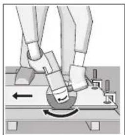
Illustration of a robotic arm with motion arrows indicating movement (no text or symbols)The power tool must always work in an up-grinding motion. Otherwise, there is a risk that it will be pushed uncontrolled out of the cut. For best results when cutting profiles and rectangular tubing, start at the smallest cross section.
Cutting stone
▶ Provide sufficient dust extraction when cutting stone.
▶ Wear a dust mask.
The power tool may be used only for dry cutting/grinding.
For cutting stone, it is best to use a diamond cutting disc. When using the extraction guard for cutting with a cutting guide (23), the dust extractor must be approved for extracting stone dust. Suitable dust extractors are available from Bosch.
Switch on the power tool and position it with the front part of the guide block on the workpiece. Move the power tool with a moderate feed motion that is suited to the material being machined.
When cutting especially hard materials such as concrete with a high pebble content, the diamond cutting disc can overheat and become damaged as a result. This is clearly indicated by circular sparking, rotating with the diamond cutting disc.
If this happens, stop cutting and allow the diamond cutting disc to cool down by running the power tool for a short time at maximum speed with no load.
If work is noticeably slower and circular sparking is present, this indicates that the diamond cutting disc has become blunt. You can resharpen the disc by briefly cutting into abrasive material (e.g. lime-sand brick).
Information on structural design
Recesses in load-bearing walls are subject to country-specific regulations. These regulations must be observed under all circumstances. Seek advice from the responsible structural engineer, architect or construction supervisor before starting work.
Maintenance and Service
Maintenance and Cleaning
▶ Pull the plug out of the socket before carrying out any work on the power tool.
▶ To ensure safe and efficient operation, always keep the power tool and the ventilation slots clean.
In extreme conditions, always use a dust extractor if possible. Blow out ventilation slots frequently and install a residual current device (RCD) upstream. When machining metals, conductive dust can settle inside the power tool, which can affect its protective insulation.
Store and handle the accessories carefully.
In order to avoid safety hazards, if the power supply cord needs to be replaced, this must be done by Bosch or by an after-sales service centre that is authorised to repair Bosch power tools.
After-Sales Service and Application Service
Our after-sales service responds to your questions concerning maintenance and repair of your product as well as spare parts. You can find explosion drawings and information on spare parts at: www.bosch-pt.com
The Bosch product use advice team will be happy to help you with any questions about our products and their accessories.
In all correspondence and spare parts orders, please always include the 10-digit article number given on the nameplate of the product.
Great Britain
Robert Bosch Ltd. (B.S.C.)
P.O. Box 98
Broadwater Park
North Orbital Road
Denham Uxbridge
UB 9 5HJ
At www.bosch-pt.co.uk you can order spare parts or arrange the collection of a product in need of servicing or repair.
Tel. Service: (0344) 7360109
E-Mail: boschservicecentre@bosch.com
You can find further service addresses at:
www.bosch-pt.com/serviceaddresses
Disposal
The power tool, accessories and packaging should be recycled in an environmentally friendly manner.
Do not dispose of power tools along with household waste.
Only for EU countries:
According to the European Directive 2012/19/EU on Waste Electrical and Electronic Equipment and its implementation into national law, power tools that are no longer usable must be collected separately and disposed of in an environmentally friendly manner.
If disposed incorrectly, waste electrical and electronic equipment may have harmful effects on the environment and human health, due to the potential presence of hazardous substances.
Only for United Kingdom:
According to The Waste Electrical and Electronic Equipment Regulations 2013 (SI 2013/3113) (as amended), products that are no longer usable must be collected separately and disposed of in an environmentally friendly manner.
Français
text_image
Technical diagram showing mechanical assembly with labeled parts and magnified viewsnatural_image
Illustration of a robotic arm performing a circular motion on a surface, with no visible text or symbols.Robert Bosch (France) S.A.S.
www.bosch-pt.com/serviceaddresses
natural_image
Mechanical device with gear meshing and tool insertion, shown in two circular insets (no text or symbols)natural_image
Illustration of robotic arm positioning with motion arrows (no text or symbols)Rebarbadora GWS 2000 J GWS 2000 P GWS 2200 J GWS 2200 P GWS 2400 J GWS 2400 P
Montar as ferramentas de lixar
natural_image
Diagram of a mechanical device with gear and adjustment tool, showing two views of the component (no text or symbols present)natural_image
Illustration of a robotic arm with a curved arm and motion arrow (no text or symbols)www.bosch-pt.com/serviceaddresses
Eliminação
Smerigliatrice angolare GWS 2000 J GWS 2000 P GWS 2200 J GWS 2200 P GWS 2400 J GWS 2400 P
natural_image
Diagram of a mechanical device with gear and adjustment mechanism, showing no text or symbolsnatural_image
Illustration of a robotic arm with motion arrows indicating movement (no text or symbols)www.bosch-pt.com/serviceaddresses
Smaltimento
Snelspanmoer SDS-elic
natural_image
Diagram of a mechanical device with a cutting tool and meshed plate, showing two views of the component (no text or symbols present)natural_image
Illustration of a robotic arm with a rotating head and mechanical components (no text or symbols)www.bosch-pt.com/serviceaddresses
Afvalverwijdering
natural_image
Diagram of a robotic arm with a tool interacting with a gear and a circular component, showing mechanical components (no text or symbols present)natural_image
Illustration of a robotic arm with a curved mechanical component and directional arrows (no text or symbols)Bosch Service Center
Telegrafvej 3
2750 Ballerup
På www.bosch-pt.dk kan der online bestilles reservedele eller oprettes en reparations ordre.
Tlf. Service Center: 44898855
Fax: 44898755
E-Mail: vaerktoej@dk.bosch.com
www.bosch-pt.com/serviceaddresses
Bortskaffelse
text_image
Technical diagram showing mechanical assembly with magnified views of a component and tool, including angular measurement and angle markings.natural_image
Mechanical diagram showing a robotic arm with a rotating base and foot, no text or symbols presentBosch Service Center
Telegrafvej 3
2750 Ballerup
Danmark
Tel.: (08) 7501820 (inom Sverige)
Fax: (011) 187691
www.bosch-pt.com/serviceaddresses
Avfallshantering
Overflatesliping (skrubbing):
$$ a _ {h} = 7, 5 \mathrm{m} / \mathrm{s} ^ {2}, K = 1, 5 \mathrm{m} / \mathrm{s} ^ {2}, $$
Sliping med slipeskive:
$$ a _ {h} = 4, 5 \mathrm{m} / \mathrm{s} ^ {2}, K = 1, 5 \mathrm{m} / \mathrm{s} ^ {2}. $$
Vernedeksel for slipping
text_image
Technical diagram showing mechanical assembly with magnified views of a component and tool, labeled with Chinese characters.natural_image
Illustration of a robotic arm with joints and motion arrows indicating movement (no text or symbols)www.bosch-pt.com/serviceaddresses
Deponering
text_image
Technical diagram showing mechanical assembly with magnified views of a component and tool, labeled with Chinese characters.natural_image
Illustration of a robotic arm with motion arrows indicating movement (no text or symbols)www.bosch-pt.com/serviceaddresses
Hävitys
Γωνιακός λειαντήρας GWS 2000 J GWS 2000 P GWS 2200 J GWS 2200 P GWS 2400 J GWS 2400 P
natural_image
Diagram of a mechanical device with a tool interacting with a gear and a rotating knob, shown in two views (no text or symbols present)natural_image
Illustration of a robotic arm performing a circular motion maneuver (no text or symbols)www.bosch-pt.com/serviceaddresses
Απόσυρση
natural_image
Technical illustration of a mechanical device with circular components and a tool, showing internal components (no text or symbols)text_image
maks. [mm] [mm] D b d [dev/ dak] [m/sn]

230 8 22,2 6500 80
180--650080
100 30 M14 8500 45
Toz ve talaş emme
natural_image
Illustration of a robotic arm with a circular motion indicator (no text or symbols)www.bosch-pt.com/serviceaddresses
Tasfiye
Szlifierka katowa GWS 2000 J GWS 2000 P GWS 2200 J GWS 2200 P GWS 2400 J GWS 2400 P
natural_image
Technical illustration of a mechanical device with gear meshing and tool insertion (no text or symbols)natural_image
Illustration of a robotic arm with joints and motion arrows indicating movement (no text or symbols)Robert Bosch Sp. z o.o.
www.bosch-pt.com/serviceaddresses
Utylizacja odpadów
text_image
Technical diagram showing mechanical assembly with labeled components and directional arrows indicating motion or assembly stepsD b d [ot/min] [m/s]
![BOSCH GWS 2400 P Professional - D b d [ot/min] [m/s] - 1](/content/2026/04/592794/images/643729db2bccb3edcbd03d0e1fae80f3f7fa9f9271c9adba6ef10b04ff13b861.jpg)
230 8 22,2 6 500 80
![BOSCH GWS 2400 P Professional - D b d [ot/min] [m/s] - 2](/content/2026/04/592794/images/866d395a23e0674f128bab460395d8f6de3a5ad098c6ea8f7ef9a0ee867f0c8b.jpg)
180--650080
![BOSCH GWS 2400 P Professional - D b d [ot/min] [m/s] - 3](/content/2026/04/592794/images/4f0be0f9b99ce9659721cc467df31ed0da535116e897ca4eeab40eda8da69d00.jpg)
100 30 M14 8 500 45
natural_image
Illustration of a robotic arm with a rotating base and foot, showing motion direction (no text or symbols)Bosch Service Center PT
K Vápence 1621/16
692 01 Mikulov
www.bosch-pt.com/serviceaddresses
Likvidace
natural_image
Diagram of a mechanical device with a tool interacting with a gear and a base, showing two views of the mechanism (no text or symbols present)D b d [ot/min] [m/s]
![BOSCH GWS 2400 P Professional - D b d [ot/min] [m/s] - 1](/content/2026/04/592794/images/94fa68beeec44c8daa3824596e1fd0c4c526b2ac1b7ce89662016681a75d99bc.jpg)
230 8 22,2 6 500 80
![BOSCH GWS 2400 P Professional - D b d [ot/min] [m/s] - 2](/content/2026/04/592794/images/803769762e203a1edd6c9a02ed05d4c6bf302be74fe9d02add02f4392b2674f6.jpg)
180--650080
![BOSCH GWS 2400 P Professional - D b d [ot/min] [m/s] - 3](/content/2026/04/592794/images/94009ccddd746715b1c8f7c36b0df62d022e5d7e8ebf2a43841cb1681028c383.jpg)
100 30 M14 8 500 45
Odsávanie prachu a triesok
natural_image
Illustration of a robotic arm performing a circular motion maneuver on a platform (no text or symbols)www.bosch-pt.com/serviceaddresses
Likvidácia
natural_image
Diagram of a mechanical device with a tool interacting with a grid-patterned surface, showing two views of the tool (no text or symbols present)natural_image
Illustration of a robotic arm with motion arrows indicating movement (no text or symbols)www.bosch-pt.com/serviceaddresses
Eltávolítás
natural_image
Diagram of a mechanical device with a rotating knob and mesh grid, showing two views of the component (no text or symbols present)natural_image
Illustration of a robotic arm with motion arrows indicating movement (no text or symbols)www.bosch-pt.com/serviceaddresses
natural_image
Technical illustration of a mechanical device with a cutting tool and meshing, showing two views of the component (no text or symbols present)natural_image
Illustration of a robotic arm with motion arrows indicating movement (no text or symbols)www.bosch-pt.com/serviceaddresses
Утилізація
natural_image
Diagram of a mechanical device with a tool interacting with a grid-patterned plate, showing two views of the component (no text or symbols present)natural_image
Illustration of a robotic arm with a curved motion arrow indicating rotational movement (no text or symbols present)www.bosch-pt.com/serviceaddresses
Polizor unghiular GWS 2000 J GWS 2000 P GWS 2200 J GWS 2200 P GWS 2400 J GWS 2400 P
| Clasa de protectie | ☐/II /II /II /II /☐/II |
natural_image
Technical illustration of a mechanical device with gear meshing and tool insertion (no text or symbols)natural_image
Illustration of a robotic arm with joints and motion arrows indicating movement (no text or symbols)Service scule electrice
Strada Horia Măcelariu Nr. 30-34, sector 1 013937 București
www.bosch-pt.com/serviceaddresses
Eliminare
Ъглошлайф GWS 2000 J GWS 2000 P GWS 2200 J GWS 2200 P GWS 2400 J GWS 2400 P
natural_image
Technical illustration of a mechanical device with a cutting tool and meshed plate, showing two views of the component (no text or symbols present)natural_image
Illustration of a robotic arm with a rotating base and motion arrow (no text or symbols)Service scule electrice
Strada Horia Măcelariu Nr. 30–34, sector 1
013937 Bucureşti, România
www.bosch-pt.com/bg/bg/
www.bosch-pt.com/serviceaddresses
Бракуване
natural_image
Mechanical device with gear mesh and control panel, showing mechanical components (no text or symbols)natural_image
Mechanical diagram showing a robotic arm interacting with a circular component, with no visible text or symbols.www.bosch-pt.com/serviceaddresses
Отстранување
text_image
Technical diagram showing mechanical assembly with magnified views of a component and tool, including angular measurement and angle specification.natural_image
Illustration of a robotic arm with a curved motion arrow indicating rotational movement (no text or symbols present)Električni alat morate stalno da vodite u suprotnom smeru. Inače postoji opasnost da se nekontrolisano potisne iz reza. Prilikom razdvajanja profila i četvorougaone cevi najbolje je da postavite najmanji poprečni presek.
Rezanje kamena
Prilikom presecanja u kamenu morate se pobrinuti za dovoljno usisavanja prašine.
▶ Nosite zaštitnu masku za prašinu.
▶ Električni alat smete da upotrebljavate samo za suvi rez/suvo brušenje.
Za presecanje kamena najbolje je da upotrebljavate dijamantsku ploču za presecanje.
Prilikom primene usisne haube za rezanje sa vodećim šinama (23) mora da bude dozvoljen usisivač za usisavanje kamene prašine. Bosch nudi adekvatne usisivače.
Uključite električni alat i prednjim delom vodećih šina ga stavite na radni komad. Električni alat pomičite ravnomerno, prilagođeno materijalu koji se obraduje.
Prilikom rezanja tvrdih materijala, npr. betona sa visokim sadržajem oblutka, dijamantski disk za sečenje može da se pregreje i na taj način da se ošteti. Venac varnica koji kruži oko dijamant-ploče za presecanje jasno ukazuje na to.
U ovom slučaju prekinite rezanje i pustite dijamantski disk za sečenje da se u praznom hodu vrti kratko vreme na najviše obrtaja da bi se ohladio.
Napredak u radu koji primetno zaostaje i cirkularni venac varnica su znakovi da je dijamantski disk za sečenje postao tup. Isti možete da naoštrite kratkim rezovima u abrazivnom materijalu (npr. peščani kamen).
Napomene za statiku
Useci u nosećim zidovima podležu pravilima u zavisnosti od zemlje. Ovi propisi moraju apsolutno da se poštuju. Pre početka rada konsultujte se sa odgovornim statičarem, arhitektom ili nadležnim građevinskim šefom.
Održavanje i servis
www.bosch-pt.com/serviceaddresses
Uklanjanje dubreta
Kotni brusilnik GWS 2000 J GWS 2000 P GWS 2200 J GWS 2200 P GWS 2400 J GWS 2400 P
| Kataloška številka | 3 601 HF2 0.. 3 601 HF2 1.. 3 601 HF4 0.. 3 601 HF4 1.. 3 601 HF4 2.. 3 601 HF4 3.. | ||||||
| Nazivna moč W 2000 2000 2200 2200 2400 2400 | |||||||
| Nazivno število vrtljajev | min^-1 | 6500 | 6500 | 6500 | 6500 | 6500 | |
| Najv. premer brusilne plošče | mm | 230 | 230 | 230 | 230 | 230 | |
| Navoj brusilnega vretena | M14 | M14 | M14 | M14 | M14 | ||
| Najv. dolžina navoja brusilnega vretena | mm | 25 | 25 | 25 | 25 | ||
| Zaščita pred ponovnim zagonom | ● - ● - ● - | ||||||
| Mehak zagon ● - ● - ● - | |||||||
| Teža po EPTA-Procedure 01:2014 | |||||||
| - z dodatnim ročajem za blaženje tresljajev | kg | 5,2 | 5,1 | 5,5 | 5,4 | 5,5 | 5,4 |
| - s standardnim dodatnim ročajem | kg | 5,1 | 5,0 | 5,4 | 5,3 | 5,4 | 5,3 |
| Razred zaščite | ☐/II /II /II /II /☐/II | ||||||
natural_image
Diagram of a mechanical device with a tool interacting with a grid-patterned plate, showing two views of the tool (no text or symbols present)natural_image
Illustration of a robotic arm with a rotating base and mechanical components (no text or symbols)www.bosch-pt.com/serviceaddresses
Odlaganje
Električno orodje, pribor in embalažo je treba dostaviti v okolju prijazno ponovno predelavo.
natural_image
Technical illustration of a mechanical device with gear meshing and tool insertion (no text or symbols)natural_image
Illustration of a robotic arm with motion arrows indicating movement (no text or symbols)Električni alat mora se uvijek voditi protuhodno. U suprotnom postoji opasnost da se nekontrolirano istisne iz reza. Kod rezanja profila i četverokutnih cijevi najbolje je da stavite na najmanji presjek.
Rezanje kamena
Kod rezanja kamena treba osigurati dovoljno usisavanje prašine.
▶ Nosite zaštitnu masku protiv prašine.
238 | Eesti
www.bosch-pt.com/serviceaddresses
Zbrinjavanje
Nurklihvmasin GWS 2000 J GWS 2000 P GWS 2200 J GWS 2200 P GWS 2400 J GWS 2400 P
| Tootenumber | 3 601 HF2 0.. | 3 601 HF2 1.. | 3 601 HF4 0.. | 3 601 HF4 1.. | 3 601 HF4 2.. | 3 601 HF4 3.. | |
| Nimi-sisendvõimsus | W 2000 | 2000 | 2200 | 2200 | 2400 | 2400 | |
| Nimi-pöörlemiskiirus | min^-1 | 6500 | 6500 | 6500 | 6500 | 6500 | |
| Lihvketta max läbimõõt | mm | 230 | 230 | 230 | 230 | 230 | 230 |
| Lihvspindli keere M14 M14 M14 M14 M14 | |||||||
| Lihvspindli keerme max pikkus | mm | 25 | 25 | 25 | 25 | 25 | |
| Taaskäivitumis-kaitse | ● - ● - ● - | ||||||
| Sujuvkäivitus ● - ● - ● - | |||||||
| Kaal EPTA-Procedure 01:2014 järgi | |||||||
| - vibratsiooni summutava lisa-käepidemega | kg | 5,2 | 5,1 | 5,5 | 5,4 | 5,5 | 5,4 |
Nurklihvmasin GWS 2000 J GWS 2000 P GWS 2200 J GWS 2200 P GWS 2400 J GWS 2400 P
| - standardse lisa-käepidemega | kg 5,1 5,0 5,4 5,3 5,4 5,3 | ||||
| Kaitseklass | ☐/II /II /II /II /☐/II | ☐ | ☐ | ☐ | ☐ |
natural_image
Diagram showing mechanical components with magnified views of a gear assembly (no text or symbols)natural_image
Illustration of a robotic arm with joints and motion arrows indicating movement (no text or symbols)www.bosch-pt.com/serviceaddresses
natural_image
Technical illustration of a mechanical device with gear and adjustment knobs, showing internal components (no text or symbols)natural_image
Illustration of a robotic arm with a rotating wheel and mechanical components (no text or symbols)www.bosch-pt.com/serviceaddresses
text_image
Diagram illustrating a mechanical device with labeled parts and directional arrows, showing components like a dial and adjustment mechanism.natural_image
Illustration of a robotic arm with motion arrows indicating movement (no text or symbols)www.bosch-pt.com/serviceaddresses
Šalinimas
Declaration of Conformity
Angle Grinder Article number
GWS 2200 P 3 601 HF4 170
We declare under our sole responsibility that the stated products comply with all applicable provisions of the regulations listed below and are in conformity with the following standards.
Technical file at: Robert Bosch Ltd. (PT/SOP-GB), Broadwater Park, North Orbital Road, Uxbridge UB9 5HJ, United Kingdom
The Supply of Machinery (Safety) Regulations 2008
The Electromagnetic Compatibility Regulations 2016
The Restriction of the Use of Certain Hazardous Substances in
Electrical and Electronic Equipment Regulations 2012
EN 60745-1:2009+A11:2010
EN 60745-2-3:2011+A2:2013+A11:2014+
A12:2014+A13:2015
EN IEC 55014-1:2021
EN IEC 55014-2:2021
EN IEC 61000-3-2:2019+A1:2021
EN 61000-3-11:2019
EN IEC 63000:2018

BOSCH
Vonjy Rajakoba
Managing Director - Bosch UK
text_image
Damm J. 2017 1.Robert Bosch Power Tools GmbH, 70538 Stuttgart, Germany represented (in terms of the above regulations) by
Robert Bosch Limited, Broadwater Park, North Orbital Road, Uxbridge UB9 5HJ, United Kingdom
Martin Sibley
Head of Sales Operations and Aftersales

text_image
lunla dlyRobert Bosch Ltd. Broadwater Park, North Orbital Road, Uxbridge UB9 5HJ, United Kingdom, as authorised representative acting on behalf of Robert Bosch Power Tools GmbH, 70538 Stuttgart, Germany
Place of issue: Uxbridge Date of issue: 27/09/2022