
633936 - Carpentry tool SILVERLINE - Free user manual and instructions
Find the device manual for free 633936 SILVERLINE in PDF.

| Product Type | Dovetail Jig |
| Brand | Silverline |
| Model | 633936 |
| Weight | 9.5 kg |
| Comb Tooth Spacing | 12.7 mm (1/2") |
| Recommended Copy Ring Diameter | 11.1 mm (7/16") |
| Recommended Dovetail Bit | Shank 6.35 mm (1/4"), body 12.7 mm (1/2") x 14° |
| Horizontal Width Range | 140 to 300 mm |
| Vertical Width Range | 150 to 275 mm |
| Maximum Material Thickness | 32 mm |
| Material | Steel / aluminium alloy |
| Intended Use | Making dovetail joints for drawers, boxes and chests |
| Main Functions | Precise router guidance, stop adjustments, removable comb, horizontal and vertical clamping |
| Safety | Wear PPE (safety glasses, dust mask, hearing protection). Keep work area clean and well lit. |
| Maintenance and Cleaning | Clean regularly with a soft brush or vacuum. Remove resin with a suitable solvent. |
| Spare Parts and Repairability | Clamping levers, knobs, copy rings and bits available as optional accessories |
| Warranty | Lifetime (subject to terms and conditions, registration within 30 days) |
Frequently Asked Questions - 633936 SILVERLINE
User questions about 633936 SILVERLINE
0 question about this device. Answer the ones you know or ask your own.
Ask a new question about this device
Download the instructions for your Carpentry tool in PDF format for free! Find your manual 633936 - SILVERLINE and take your electronic device back in hand. On this page are published all the documents necessary for the use of your device. 633936 by SILVERLINE.
USER MANUAL 633936 SILVERLINE
SILVERLINEC® 10 Llc 300mm
Dovetail Jig 300mm 300mm Width Capacity
STER ONLINE® SILVERLINEC® teilin 300mm
Dovetail Jig 300mm 300mm Width Capacity
English 4
Français 8
Deutsch 12
Español ...... 16
Italiano 20
Nederlands......24
Specification
Template: 12.7mm ( 1/2 )
Guide bush (not included):....11.1mm ( 7/16 )
Router cutter (not included): 6.35mm (1/4")
shank -12.7mm (½") x 14° dovetail
Maximum material thickness: 32mm
Horizontal width range: 140 – 300mm
Vertical width range: 150 - 275mm
Weight: 9.5kg
Safety Warnings
WARNING Read all safety warnings and all instructions. Failure to follow the warnings and instructions may result in electric shock, fire and/or serious injury.
Save all warnings and instructions for future reference.
Work Area Safety
a) Keep work area clean and well lit. Cluttered or dark areas invite accidents.
b) Do not operate tools in explosive atmospheres, such as in the presence of flammable liquids, gases or dust.
c) Keep children and bystanders away while operating a powered tool. Distractions can cause you to lose control.
Personal Safety
a) Stay alert, watch what you are doing and use common sense when operating a powered tool. Do not use a powered tool while you are tired or under the influence of drugs, alcohol or medication. A moment of inattention while operating a powered tool may result in serious personal injury.
b) Use personal protective equipment. Always wear eye protection. Protective equipment such as dust mask, non-skid safety shoes, hard hat, or hearing protection used for appropriate conditions will reduce personal injuries.
c) Prevent unintentional starting. Ensure the switch is in the off-position when not operating the tool and make use of other safety features which prevent unintentional starting.
d) Remove any adjusting key or wrench before turning the powered tool on. A wrench or a key left attached to a rotating part of the tool may result in personal injury.
e) Do not overreach. Keep proper footing and balance at all times. This enables better control of the tool in unexpected situations.
f) Dress properly. Do not wear loose clothing or jewelry. Keep your hair, clothing and gloves away from moving parts. Loose clothes, jewelry or long hair can be caught in moving parts.
g) If devices are provided for the connection of dust extraction and collection facilities, ensure these are connected and properly used. Use of dust collection can reduce dust-related hazards.
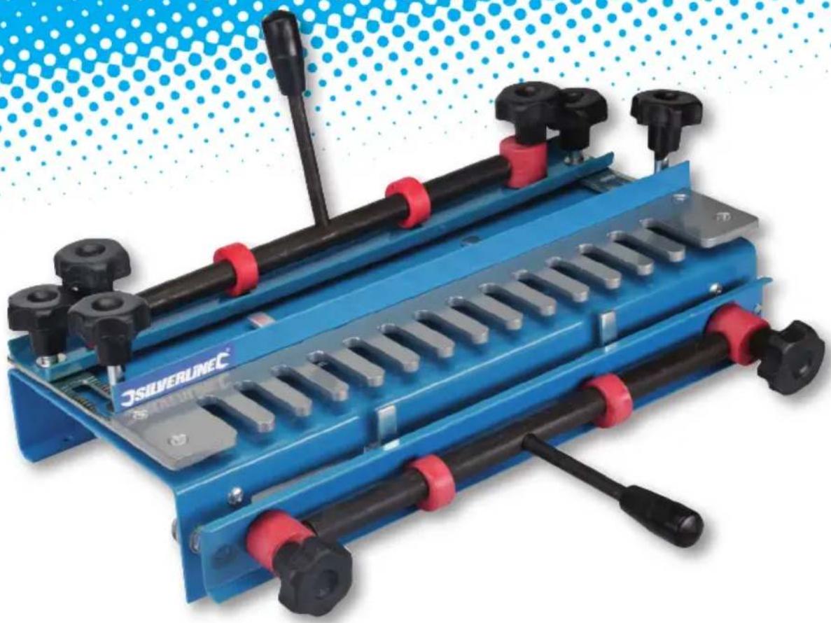
Product Familiarisation
1 Horizontal Clamping Lever
2 Horizontal Clamping Knobs
3 Template Position Knobs
4 Fence Position Knobs
5 Fence
6 Horizontal Stop Bar
7 Template
8 Vertical Stop Bar
9 Vertical Clamping Knobs
10 Vertical Clamping Lever
Unpacking and assembly
- Carefully unpack the dovetail jig, and remove all packaging materials. Beware of sharp edges
- The Horizontal Clamping Lever (1) and the Vertical Clamping Lever (10) are supplied loose. The levers should be securely screwed into the threaded holes provided so that, when clamped, the horizontal lever is behind the jig and the vertical lever is down away from the Template (7)
Mounting
- This dovetail jig should always be securely mounted to the front edge of a sturdy workbench before use
- The jig should be fixed to the bench using wood screws through the four small holes in the jig frame
- If a permanent installation is not required the jig may be mounted to a board that can be easily clamped to a workbench. It is important the board is long enough so the clamps do not obstruct use of the jig
Operating Instructions
WARNING: The cutter must not contact any part of the jig. Always use the correct-sized guide bush and cutter. Incorrect sizes will make an un-usable joint and may damage the jig.
Configuring your router
Note: These instructions are specific to the recommended router accessories to use with this dovetail jig. Use of other accessories to create other joints is possible but beyond the scope of this manual.
The jig is compatible with both 1/4 " and 1/2 " routers including equivalent metric sizes. The router may need an additional collet or reducer so it can accept 1/4 " router bits.
- Fit a base to your router that will allow fitment of guide bushes
- Install a guide bush of 11.1-12mm or 3/16 " outer diameter so that the router can move smoothly between the slots of the 1/2 " Template (7). The guide bush depth must not exceed the thickness of the template
- Fit a 12.7mm ( 1/2 ) dovetail 14° cutter with a 1/4 " shank. The dovetail cutter height needs to be set so that the cutting blades will not contact the template in use but the cutting blade starts cutting at the surface of the wood. The dovetail cutter should be approximately 17mm height from the base plate of the router. See Fig A
Preparation
This jig is suitable for the creation of dovetail joints needed for drawers, boxes and chests. The information presented below is general guidance only. Familiarisation with this jig over time is necessary to achieve the desired results. Fine adjustment of some measurements is required to get an exact fit.
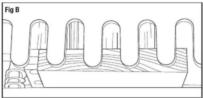
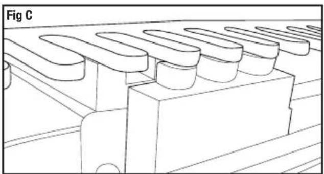
The jig is used to create both the tails and pins of the dovetail joint in one process. This is achieved by using an offset position between two clamped pieces of wood. See fig B which shows the wood position for four tails of the dovetail joint on the vertical wood before cutting and fig C which shows three tails of the dovetail joints after cutting. The sides of the slots where the tail fits into are the pins.
- Wood must be cut to the correct size, with square cut ends. Allow for the depth of the joint when calculating wood sizes
- Use a pencil to label the wood indicating front, back, left, right, inside, outside and any other information that might assist in cutting the wood correctly. For example, write matching numbers on the ends of the wood to be joined together, and note which end is for tails and which part is pins
Important: The use of a square is recommended to ensure that correct angles are achieved in all stages of setting up the dovetail jig. Accurate alignment of the wood is crucial to achieving a good quality joint. Practising with scrap material is highly recommended to develop accuracy when using the jig.
Setting the vertical and horizontal stop bars
Note: A spanner (not supplied) is required to adjust the Horizontal Stop Bars (6) and the Vertical Stop Bars (8).
- Loosen the Horizontal Clamping Knobs (2) and Vertical Clamping Knobs (9), and raise the Horizontal Clamping Lever (1) and the Vertical Clamping Lever (10) to allow access to the stop bars adjustment nuts easily
- Set the left-hand Horizontal Stop Bar (6) to a position where the Template (7) indicates a suitable place for the first dovetail joint female slot for the size of the wood so that the dovetail joints are evenly spaced across the wood. The left-hand Vertical Stop Bar (8) should be set so that it is positioned 12.7mm ( 1/2 ) to the right of the Horizontal Stop Bar (6). This is the offset which is approximately the width of a finger of the template
- The initial horizontal stop bar position in relation to the template fingers may vary slightly depending on how much border is required. The border is the distance from the edge of the vertical wood to the first dovetail tail. The offset between the two pieces of wood is always the thickness of a template finger 12.7mm ( 1/2 ) in order to line up two equal width pieces of wood after jointing. Once cut, the wood in Fig B will have a smaller border than that in Fig C
- Use the right-hand side horizontal and vertical stop bars to secure and align larger pieces of wood more centrally in the jig. The right-hand side stop bars can also be used in preference to the left-hand side or used for another two pieces of wood secured at the same time as the left side so two dovetail joints can be made in one operation
- When securing two sets of wood, the left-hand or right-hand side Horizontal Clamping Knobs (2) and Vertical Clamping Knobs (9) can be used instead of the Horizontal Clamping Lever (1) and the Vertical Clamping Lever (10) to allow releasing or fitting of wood to the left or right side only without affecting the position of the wood already fitted on the other side
- Once the stop bars are in the correct offset position lining up the two pieces of wood exactly level when jointed, avoid adjusting the stop bar position again. This is only possible if the same size wood is being worked on. Alternatively, once the correct offset position has been found between the horizontal and vertical stop bars, an offset spacer can be made from a small piece of wood to that exact measurement. This will enable the offset position to be set quickly and accurately even when using different size pieces of wood
Clamping and positioning the wood
- Pull the Horizontal Clamping Lever (1) towards the back of the jig, loosen the two Horizontal Clamping Knobs (2) and slide the horizontal piece of wood into the jig from the rear
- The wood should pass underneath the fence (5) and the Template (7). The left-hand side of the wood should be lying against the left Horizontal Stop Bar (6) and the front of the wood should be level with the front of the main body of the jig to allow for the vertically placed wood to be positioned in front of it (Fig B)
- Tighten the Horizontal Clamping Knobs (2) so the clamp is very close to the surface of the wood. Recheck the position of the wood and pull the horizontal clamping lever towards the front of the jig to secure the wood
- The clamp needs to be set so that operating the clamping lever allows the wood to be inserted and secured without additional use of the clamping knobs
- Do not force the clamping lever if there is too much resistance when operating. Loosen the clamping knobs to adjust it to the optimum setting that holds the wood securely but does not put unnecessary strain on the clamping mechanism to prevent it being damaged
- Pull the Vertical Clamping Lever (10) up so it is in the unclamped position and loosen the Vertical Clamping Knobs (9)
-
If the vertical piece of wood has already been cut for the joint at the other end, make sure the wood is inserted in the correct way. Once the dovetail joint is cut the vertical wood in the jig fits to the horizontal wood at 180° to its cut position, as if hinged at the cut position and rotated 180° upwards
-
Insert the vertical piece of wood from below into the front of the jig. The wood should pass behind the front clamp assembly, and be in contact with the vertical edge of the frame
- Position the left side of the wood against the left-hand side Vertical Stop Bar (8)
- As per the horizontal clamp adjust the clamp so that the wood can be inserted and secured simply by operating the clamping lever
- Align the vertical wood so the height is parallel with the horizontal wood as shown in Fig B
- Move the vertical clamping lever to the down position to lock the wood in place
Adjusting of the template position
To adjust the position of the Template (7) to allow for correct positioning loosen the Template Position Knobs (3) and adjust the template position to suit the thickness of the wood making sure the template is even on both sides. The tips of the template should be approximately 2.5mm back from the front edge of the vertical piece of wood. Ensure the template is kept parallel with the jig body.
Adjusting the fence
The fence controls how deep the female dovetail slots are by limiting the movement of the base of the router. There are no set values of distance as this value depends on the size of the router base and the thickness of the wood. The formula for this is:
Distance = (2 x thickness of vertical wood) + (½ width of router base) - (cutter radius)
This is measured from the fence to the end of the fingers on the Template (7). If you have used the recommended 1/2 " dovetail cutter, the cutter radius value will be 6.35mm ( 1/4 ")
Note: If using a router without a completely round base (possibly a router that has 2 flat sides to its base) measure the distance from the centre of the base to the edge closest to the centre of the base. When operating the router remember to work to the base side you have measured to. If you set to the widest distance of the base there is a risk of the cutter coming into contact with the jig if you then use the side of the base closest to the cutter.
Cutting a dovetail joint
- Ensure both the router and jig are set up using the instructions above, including using scrap wood in the jig if this is your first dovetail joint
- Wear any necessary personal protective equipment including a face mask especially if there is any risk of toxic particles (for example, from man-made composite woods)
- Set the router to a speed that does not exceed that of the maximum speed of the dovetail cutter
- Place the router onto the Template (7) with the router cutter not touching the wood but close to it in an ideal position to start cutting
- Hold the router securely and turn on, allow the motor to reach full speed
- Carefully begin cutting, allowing the router guide bush to follow the slots of the template, entering the slot on the left side and following the curve of the slot so that the guide bush is against the right side of the slot when leaving the slot. Do not cut into slots individually but instead cut in one process carefully going around the shape of the template. The end result will look like Fig C
-
While operating the router make sure the cutter does not contact any part of the jig and do not lift the router while cutting. Once the cut is complete, switch off the router and allow the cutter time to stop rotating before removing carefully from the template
-
Once the cut has been made, remove the wood from the jig and check the joint. A correctly cut joint should be neither too loose nor too tight to connect. Using a light mallet can be used to tap the joint into place if it is a tight joint.
- If the joint is not correct or if more practising is required, saw off the ends of the test pieces so they can be used again
Optional Accessories
Contact your Silverline stockist for a range of accessories suitable for use with this product including;
245122 - 10 Piece Guide Bush Set in Case (including a 11.1mm ( 1/16 ") guide bush)
792084 - 12 Piece 1/4 " Router Bit Set (including a 1/2 " 14° dovetail cutter)
656577 - 24 Piece 1/4 " Router Bit Set (including a 1/2 " 14° dovetail cutter)
Maintenance
Keep your dovetail jig clean. Do not allow dust to build up around the jig. Clean regularly with a soft brush or vacuum, clean resin off with a suitable solvent
Troubleshooting
| Problem Solution | |
| Dovetail joint is not at a 90° angle Recheck that wood is correctly fitted and clamped | |
| Dovetail joint is at an angle with the two pieces of wood not level but slightly angled apart | Recheck that the angle of wood to the Horizontal Stop Bars and Vertical Stop Bars is correct using a square and the angle between the stop bars is correct |
| Where jointed the two pieces of wood are slightly stepped and not level | Offset of the stop bar needs adjustment |
| The dovetail pins are too long or short | Fence position needs adjustment towards or away from the Template (7) |
| Dovetail joint too tight | decrease the dovetail cutter height from the router base |
| Dovetail joint too loose | increase the dovetail cutter height from the router base |
| Splintering of the wood as the cutter leaves the workpiece | Clamp another piece of wood over the vertical wood if possible to prevent splintering |
| More careful router operation | |
| Scribe a line across the wood at the cut height to prevent splintering | |
| Cut with the grain | |

Guaranteed Forever
*Register online within 30 days. Terms & Conditions apply

Garantie à vie
- SILVERLINEC® 10 LLC 300MM
- DOVETAIL JIG 300MM 300MM WIDTH CAPACITY
- STER ONLINE® SILVERLINEC® TEILIN 300MM
- SPECIFICATION
- SAFETY WARNINGS
- WORK AREA SAFETY
- PERSONAL SAFETY
- PRODUCT FAMILIARISATION
- UNPACKING AND ASSEMBLY
- MOUNTING
- OPERATING INSTRUCTIONS
- CONFIGURING YOUR ROUTER
- PREPARATION
- SETTING THE VERTICAL AND HORIZONTAL STOP BARS
- CLAMPING AND POSITIONING THE WOOD
- ADJUSTING OF THE TEMPLATE POSITION
- ADJUSTING THE FENCE
- DISTANCE = (2 X THICKNESS OF VERTICAL WOOD) + (½ WIDTH OF ROUTER BASE) - (CUTTER RADIUS)
- CUTTING A DOVETAIL JOINT
- OPTIONAL ACCESSORIES
- MAINTENANCE
- GUARANTEED FOREVER
- GARANTIE À VIE
Brand : SILVERLINE
Model : 633936
Category : Carpentry tool