
TTS56A - Speaker RCF - Free user manual and instructions
Find the device manual for free TTS56A RCF in PDF.
| Product type | Active subwoofer |
| Brand | RCF |
| Model | TTS56A |
| Bandwidth | 30-120 Hz |
| Max SPL level | 145 dB |
| Crossover frequency (active filter) | 60 Hz / 90 Hz (selectable) |
| Transducers | 2 neodymium 21" woofers with 4.5" (115 mm) voice coil |
| Amplification | 2 digital modules of 3400 W each with PFC power supplies |
| Mains voltage | 115 V / 230 V (±15 %) - automatic selection |
| Fuses | F1: F15AL250V~; F2, F3: T10AL250V~ |
| Audio input/output | Female XLR (input), Male XLR (link), Male XLR (filtered output) |
| Network input/output | Ethercon (CAT5) for RDNet |
| Mains connector | PowerCON (lockable) |
| Settings | Sensitivity (-2 to +10 dBu), low cut (30/45 Hz), active filter crossover (60/90 Hz), delay (0-20 m), cardioid directivity, RDNet bypass |
| DSP processing | High-pass filters, low-pass filters, equalization, fast limiter, compressor, RMS limiter |
| Dimensions (W x H x D) | 550 mm x 1100 mm x 950 mm |
| Net weight | 90 kg |
| Cabinet material | Baltic birch plywood with polymer coating |
| Transport fittings | 4 blue 100 mm casters, 6 molded handles, forklift bars |
| Safety | Do not suspend by handles; use dedicated rigging points |
Frequently Asked Questions - TTS56A RCF
User questions about TTS56A RCF
0 question about this device. Answer the ones you know or ask your own.
Ask a new question about this device
Download the instructions for your Speaker in PDF format for free! Find your manual TTS56A - RCF and take your electronic device back in hand. On this page are published all the documents necessary for the use of your device. TTS56A by RCF.
USER MANUAL TTS56A RCF
HIGH OUTPUT ACTIVE SUBWOOFER
ENGLISH 4
ITALIANO 14
FRANÇAIS 24
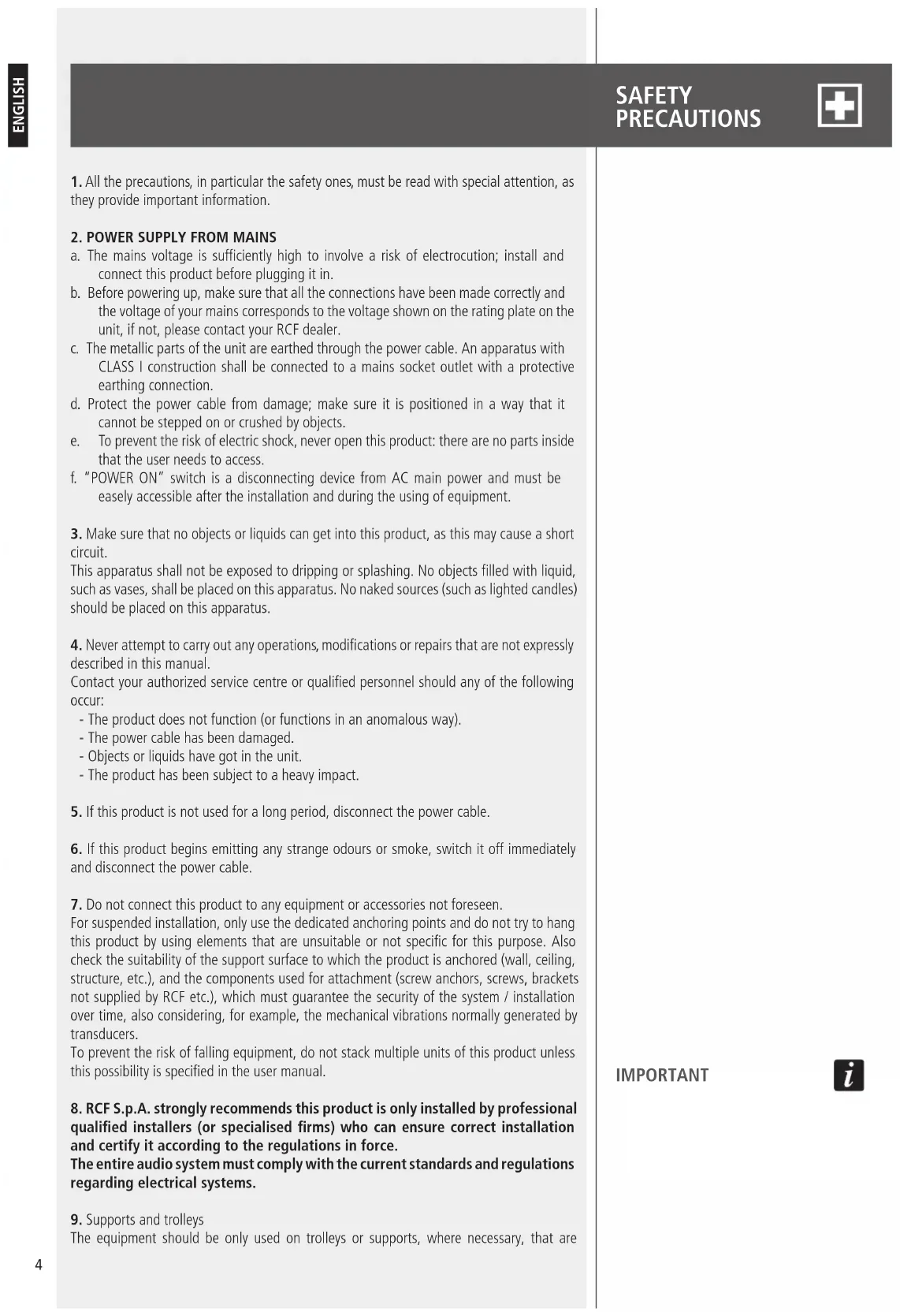
- All the precautions, in particular the safety ones, must be read with special attention, as they provide important information.
2. POWER SUPPLY FROM MAINS
a. The mains voltage is sufficiently high to involve a risk of electrocution; install and connect this product before plugging it in.
b. Before powering up, make sure that all the connections have been made correctly and the voltage of your mains corresponds to the voltage shown on the rating plate on the unit, if not, please contact your RCF dealer.
c. The metallic parts of the unit are earthed through the power cable. An apparatus with CLASS I construction shall be connected to a mains socket outlet with a protective earthing connection.
d. Protect the power cable from damage; make sure it is positioned in a way that it cannot be stepped on or crushed by objects.
e. To prevent the risk of electric shock, never open this product: there are no parts inside that the user needs to access.
f. "POWER ON" switch is a disconnecting device from AC main power and must be easily accessible after the installation and during the using of equipment.
3. Make sure that no objects or liquids can get into this product, as this may cause a short circuit.
This apparatus shall not be exposed to dripping or splashing. No objects filled with liquid, such as vases, shall be placed on this apparatus. No naked sources (such as lighted candles) should be placed on this apparatus.
- Never attempt to carry out any operations, modifications or repairs that are not expressly described in this manual.
Contact your authorized service centre or qualified personnel should any of the following occur:
- The product does not function (or functions in an anomalous way).
- The power cable has been damaged.
- Objects or liquids have got in the unit.
-
The product has been subject to a heavy impact.
-
If this product is not used for a long period, disconnect the power cable.
-
If this product begins emitting any strange odours or smoke, switch it off immediately and disconnect the power cable.
-
Do not connect this product to any equipment or accessories not foreseen.
For suspended installation, only use the dedicated anchoring points and do not try to hang this product by using elements that are unsuitable or not specific for this purpose. Also check the suitability of the support surface to which the product is anchored (wall, ceiling, structure, etc.), and the components used for attachment (screw anchors, screws, brackets not supplied by RCF etc.), which must guarantee the security of the system / installation over time, also considering, for example, the mechanical vibrations normally generated by transducers.
To prevent the risk of falling equipment, do not stack multiple units of this product unless this possibility is specified in the user manual. - RCF S.p.A. strongly recommends this product is only installed by professional qualified installers (or specialised firms) who can ensure correct installation and certify it according to the regulations in force.
The entire audio system must comply with the current standards and regulations regarding electrical systems. - Supports and trolleys
The equipment should be only used on trolleys or supports, where necessary, that are
IMPORTANT
recommended by the manufacturer. The equipment / support / trolley assembly must be moved with extreme caution. Sudden stops, excessive pushing force and uneven floors may cause the assembly to overturn.
- There are numerous mechanical and electrical factors to be considered when installing a professional audio system (in addition to those which are strictly acoustic, such as sound pressure, angles of coverage, frequency response, etc.).
- Hearing loss
Exposure to high sound levels can cause permanent hearing loss. The acoustic pressure level that leads to hearing loss is different from person to person and depends on the duration of exposure. To prevent potentially dangerous exposure to high levels of acoustic pressure, anyone who is exposed to these levels should use adequate protection devices. When a transducer capable of producing high sound levels is being used, it is therefore necessary to wear ear plugs or protective earphones. See the manual technical specifications to know the maximum sound pressure level.
IMPORTANT NOTES
To prevent the occurrence of noise on line signal cables, use screened cables only and avoid putting them close to:
- Equipment that produces high-intensity electromagnetic fields.
- Power cables.
- Loudspeaker lines.
IMPORTANT NOTES

OPERATING PRECAUTIONS

OPERATING PRECAUTIONS
- Place this product far from any heat sources and always ensure an adequate air circulation around it.
- Do not overload this product for a long time.
- Never force the control elements (keys, knobs, etc.).
- Do not use solvents, alcohol, benzene or other volatile substances for cleaning the external parts of this product.
IMPORTANT NOTES
Before connecting and using this product, please read this instruction manual carefully and keep it on hand for future reference. The manual is to be considered an integral part of this product and must accompany it when it changes ownership as a reference for correct installation and use as well as for the safety precautions. RCF S.p.A. will not assume any responsibility for the incorrect installation and / or use of this product.
WARNING: to prevent the risk of fire or electric shock, never expose this product to rain or humidity.
IMPORTANT NOTES

WARNING

TT+ HIGH DEFINITION TOURING AND THEATRE
RCF TT+ represents another prominent chapter in the long history of RCF Sound Systems. Whether a speaker system is designed for live sound or large concert situations as well as permanent installed theatre sound applications, the paying customer now expects a level of audio fidelity and intelligibility of such a standard unsurpassed by previous generations.
This requirement has fostered the need for Audio Professionals to be able to offer a range of speaker systems combined with dedicated Processing and Amplification Technologies that are superior in Acoustic Performance and Control Technology.
RCF TT+ offers ready to use solutions and tools in true active high definition speaker systems.
INNOVATION INTEGRATION INTENSITY
Innovation. Our research and engineering faculty can today offer innovative projects with finite control of each detail, from the loudspeaker voice coil wire to the highly efficient extended dynamic amplifier topology. There are many different ingredients that go into creating quality products and systems. These include computer aided simulation software to assist the understanding of transducer behaviour and amplifier operation and the relationship of dynamics and transient response. RCF utilise over thirty state of the art software packages to identify magnetic circuits, voice coil dynamics, suspension linearity, horn dispersion simulation, crossover filters, amplifier thermal behaviour etc.
Integration. RCF is one of only a few loudspeaker manufacturers worldwide who have the ability to completely design and manufactures transducers, speaker systems and amplification and control electronics. Our 50 plus years heritage in Audio combined with our state of the art research and development and manufacturing processes allows us to seamlessly integrate all the ingredients to design and build TT+.
Intensity. The design philosophy for the new TT+ series is based upon offering the sound engineer solutions and tools that are ready to use. Key factors are the ability to sustain very high power with highly efficient sound pressure levels. Intense sound levels are created with extremely high definition and extended dynamic range. Modern construction materials result in mechanical weight ratios that are light for practical flying and portability.
TTS56-A, HIGH OUTPUT SUBWOOFER
The TTS56-A is a high power, high output active subwoofer system that sets a new standard in the touring and theatre sound reinforcement. Each transducer has been specifically designed for the application. The woofer provides large excursion and very light weight.
The TTS56-A two 21" woofers features:
- lightweight, high force, neodymium magnet assembly.
- 115 mm diameter, 33 mm length, inside-outside copper voice coil.
- Silicon reinforced double spiders.
- Carbon fiber doped, water resistant treated cone.
- Complex ventilation system for minimum power compression.
The TTS56-A input section provides:
- IN/OUT XLR connectors.
- Crossover Output XLR connector.
- System sensitivity control (linear potentiometer) (-2dBu +10dBu)
- Crossover set-up (60 Hz - 80 Hz).
- Low frequencies high pass set-up (30 Hz - 45 Hz).
- Delay set-up rotary switch.
- Cardioid set-up switch.
- By-pass switch.
- RDNet input output Ethercon connectors.
- 4 status LEDs.
TT+ HIGH DEFINITION
TOURING AND THEATRE
INNOVATION
INTEGRATION
INTENSITY
TTS56-A,
HIGH OUTPUT
SUBWOOFER
The TTS56-A amplifier section features:
- 2 x 3400 Watt Digital amplifier modules with 2 x PFC circuits.
- 7 x cooling speed controlled fans.
- Powercon AC input connector.
Vibrostop floating aluminum panel.
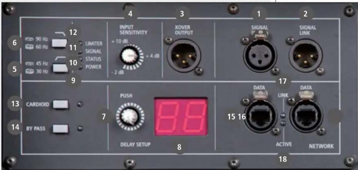
REAR PANEL
main signal XLR input (bal/unbal). The system accept female XLR input connectors and line-level signals from a mixing console or other signal source.
2 signal link XLR output. The output XLR male connector provides a loop trough for speakers daisy chaining.
3 over signal output. The output XLR male connector provides a crossover high passed signal (24 dB/octave) for satellites speakers.
4 input sensitivity. Controls the overall signal level at the input to the power amplifier. The control ranges from +10 dBu (maximum attenuation) to the -2 dBu sensitivity (maximum input gain). The centre detent is +4 dBu (nominal level required to drive the amplifier at maximum power).
5 low cut 30 / 45Hz . This switch provides an high pass 24 dB/octave filtering at 30 or 45Hz . This is really useful for indoor situations (no very low frequencies that can create resonant sound) or when all the power shall be used in the 45Hz - 100Hz range.
6 over 60 / 90Hz Provides 24 dB/octave low-pass filtering at 80Hz if released, at 110Hz if pressed. The same crossover frequency in high-pass is available from XOVER OUTPUT XLR.
7me delay encoder. This encoder provides a time delay setting expressed in meters.
8 time delay display. Display the time delay setting.
Power indicator. When the power cord is connected and the power switch is turned on, this indicator lights green.
10 status indicator. The status indicator blink orange if the main amplifier or power supply
is in faulty condition. If the status indicator lights orange, switch off the amplifier and call the closest RCF service centre.
11 Signal indicator. The signal indicator lights green if there is signal present on the main XLR input.
12 Limiter indicator. The amplifier has a built in compressor/limiter circuit to prevent clipping of the amplifiers or overdriving the transducers.
When the compressor is active the led is blinking yellow. When the soft clipping circuit is active the LED blinks orange. It is okay if the limit LED blinks occasionally. If the LED blinks frequently or lights continuously, turn down the signal level. The amplifier has a built in RMS limiter. If the RMS limiter is active the LED lights red. The RMS limiter has the purpose to prevent damages the transducers. The speaker shall never be used with the limit indicator red, continuously. Continuous operation with the RMS protection active can cause damages to the speaker.
Cardioid set-up switch. This switch provides a special equalisation and delay setting to create a cardioid pattern when the system is used in conjunction with two other TTS56-A modules.
14 By pass switch. Pressing this switch it is possible to by-pass the input panel and apply the RDNet user setting preloaded on the module.
15 data input Ethercon connector. RDNet Input CAT5 Ethercon connector.
16 data link Ethercon connector. RDNet Link CAT5 Ethercon connector.
17ink led. This green led is on if the module is addressed from the RDNet controller
18 active led. This green led is blinking if the RDNet communication is active.
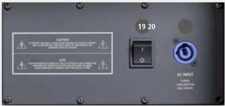
19 Power main switch. The power switch turns the AC power ON and OFF. Make sure that the sensitivity is set to +10 dBu when you turn on the speaker.
20 C POWERCON receptacle. RCF TT+ series uses a POWERCON locking 3-pole AC mains. Always use the specific power cord provided in the package.
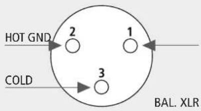
The XLR connectors use the following AES standard:
$$ \mathrm {P I N} 1 = \text {G R O U N D (S H I E L D)} $$
$$ \mathrm {P I N} 2 = \mathrm {H O T} (+) $$
$$ P I N 3 = C O L D (-) $$
At this point you can connect the power supply cable and the signal cable, but before turning on the speaker make sure that the volume control is at the minimum level (even on the mixer output). It is important that the mixer is already ON before turning on the speaker. This will avoid damage to the speakers and noisy "bumps" due to turning on parts on the audio chain. It is a good practice to always turn on speakers at last and turn them off immediately after the show.
Now you can turn ON the speaker and adjust the volume control to a proper level.
The delay is expressed in meters. The delay resolution is 0.1 up to 10 meters and 1 from 10 to 20 meters.
To set the system time delay push the delay encoder and rotate it until the wanted setting is displayed. Push the encoder again to confirm the setting.
CONNECTIONS
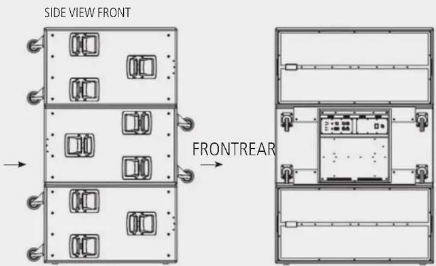
It is possible to create subwoofer cardioid systems using groups of three modules.
A group is made of three modules, the group shall be made as follow:
- 2 modules pointing in forward direction, cardioid switch released.
- 1 module pointing in backward direction, cardioid switch pressed.
- All 3 modules shall have the same settings (SYSTEM DELAY, SENSITIVITY, X-LOW CUT, X-OVER,...).
RDNet CONNECTION
The system is equipped with an RDNet connection on board.
Using an RDNet controller unit it is possible to:
- receive status information from the system (amplifiers status, signal levels, system settings,...).
- Send commands to the system (mute, solo, change sensitivity, change setting, set user eq, ...).
- See the RDNet user manual for details.
RDNet BY-PASS SWITCH
When the RDNet is present and the RDNet LINK LED is green the controller takes control over the module independently of the BY-PASS SWITCH position.
When the RDNet is not present, the BY-PASS switch act as follow:
- BY-PASS SWITCH pressed (LED ON): the system bypass the input board and reads the RDNet user settings (last configuration saved).
- BY-PASS SWITCH released (LED OFF): the system reads the input board and bypass the user setting eventually loaded ion the speaker (last configuration eventually saved).
TTS56-A DEFAULT CONFIGURATION
The TTS56-A factory default configuration (the configuration that the system reads if the BY-PASS switch is pressed) is the following:
Sensitivity +4 dBu
High pass 30 Hz
Low pass 90 Hz
Cardioid OFF
Delay
0
Bypass
OFF
User filters ALL FLAT
If the user set with RDNet a new configuration, the new configuration will be recalled when the BY-PASS switch is pressed.
BY-PASS SWITCH RDNet BY-PASS LED FUNCTION
| ON ON | ON | Reads RDNet settings | |
| OFF | ON | OFF Reads RDNet settings | |
| ON OFF | ON | Reads last saved used configuration | |
| OFF | OFF | Off Reads input panel | |
RDNet CONNECTION
RDNet BY-PASS SWITCH
TTS56-A
DEFAULT CONFIGURATION
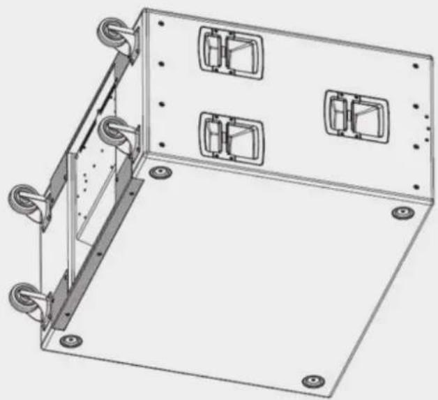
The subwoofer system is equipped with 4 × 100 mm blue rubber wheels on the back of the cabinet for transportation.
Three aluminium die cast handles with rubber hand-grip are available on each side of the speaker system.
The outdoor quality, Baltic birch plywood, cabinet is protected with heavy duty, scratch resistant, polyurea coating.
Two black coated steel bars are provided on the back of the cabinet for fork lift transportation.
INSTALLATION

WARNING: never suspend TT+ speakers by there handles. Handles are intended for transportation, not for rigging.
WARNING: always make sure that the maximum current requirement does not exceed the maximum admitted POWERCON current. In case of doubt call the closest RCF service centre.
MAINS SUPPLY
The system accept mains supply voltage115-230 (+15 / - 15%) V
FUSE F1 VALUE F15 AL 250 V ~
FUSE F2 VALUE T 10 AL 250 V ~
FUSE F3 VALUE T 10 AL 250 V ~
WARNING

WARNING

The following TTL56-A accessories are separately available:
13360135 COVER TTS56
PROTECTION COVER FOR ONE TTS56-A.
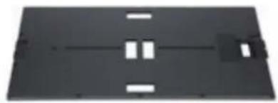
13360140 FRONT WOOD COVER TTS56-A
QUICK LOCK WOOD FRONT PROTECTION FOR TTS56-A SUBWOOFER.
To be used to protect the speaker grill during transportation.
Compatible under the TTS56-A cover.
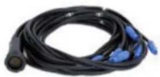
13360138 AC POWER CABLE 6XTTL55
POWER CABLE.
1 piece for every 6 pieces of TTL55 and 1 piece for every
6 pieces of TTS56 SUB are suggested.
Full compatibility with Socapex SL 419 Series.
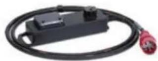
13360145 AC POWER BOX 6XTTL55
EUROPEAN STAGE BOX TO POWER 6 TTL55-A LINE ARRAY MODULES
OR 6 TTS56-A MODULES.
1 piece for every 6 pieces of TTL55 and 1 piece for every
6 pieces of TTS56 SUB are suggested.
Full compatibility with Socapex SL 419 Series.
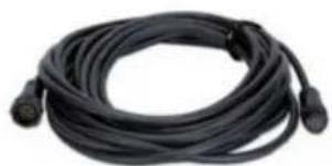
13360146 AC POWER EXTENSION TTL55
POWER EXTENSION CABLE.
20 meters AC power extension cable.
Full compatibility with Socapex SL 419 Series.

ACOUSTIC DATA
Operating frequency range
Max SPL 145 dB
Crossover
TRANSDUCERS
Low frequency
AMPLIFIERS
INPUTS
Signal Input/Output
Power Input/Output
RDNet Input/Output
CONTROLS
P PROCESSING
PHISICAL SPECIFICATIONS
Dimensions (w, h, d)
Net weight
Cabinet material
Hardware
30-120Hz
145 dB
qolrr 90 Hz
2 × 21 neodymium woofer,
4.5" voice coil
2 x 3400 Watt digital amplifiers
2 x PFC switching power supplies
XLR male/female
Powercon male/female
Cat5 Ethercon
Sensitivity Control (-2 dBu 10 dBu)
X-low cut, X-over selection
Delay set-up
Cardioid setting, RDNet bypass
User settings (RDNet)
High pass, low pass, equalisation
Crossover output processing
Fast limiter, dynamic compressor
RMS limiter
550 mm, 1100 mm, 950 mm
90 Kg
Baltic birch plywood
4 x blue 100 mm wheels
6 x die cast handles
Fork lift bars
| ON ON ON | Reads RDNet settings | ||
| OFF | ON OFF | Reads RDNet settings | |
| ON OFF ON | Reads last saved used configuration | ||
| OFF | OFF | Off | Reads input panel |
CONNECTION RDNet
PULSANTE RDNet BY-PASS
CONFIGURAIZIONE
DI DEFAULT TTS56-A
Operating frequency range
Max SPL
Crossover
TRANSDUCERS
Low frequency
AMPLIFIERS
INPUTS
Signal Input/Output
Power Input/Output
RDNet Input/Output
CONTROLS
P PROCESSING
PHISICAL SPECIFICATIONS
Dimensions (w, h, d)
Net weight
Cabinet material
Hardware
30-120Hz
145 dB
qolint 90 Hz
2 × 21 neodymium woofer,
4.5" voice coil
2 x 3400 Watt digital amplifiers
2 x PFC switching power supplies
XLR male/female
Powercon male/female
Cat5 Ethercon
Sensitivity Control (-2 dBu 10 dBu)
X-low cut, X-over selection
Delay set-up
Cardioid setting, RDNet bypass
User settings (RDNet)
High pass, low pass, equalisation
Crossover output processing
Fast limiter, dynamic compressor
RMS limiter
550 mm, 1100 mm, 950 mm
90 Kg
Baltic birch plywood
4 x blue 100 mm wheels
6 x die cast handles
Fork lift bars