
CADSHE - Controlled Mechanical Ventilation Soler & Palau - Free user manual and instructions
Find the device manual for free CADSHE Soler & Palau in PDF.
| Product type | Controlled Mechanical Ventilation (CMV) dual flow with high-efficiency static heat exchanger |
| Brand | Soler & Palau |
| Model | CADSHE |
| Dimensions (without bypass) | 218 x 160 x 109 mm |
| Dimensions (with bypass) | 292 x 218 x 180 mm |
| Power supply | 230 V / 50 Hz, current < 100 mA, consumption 1.5 W |
| Maximum airflow rate | 300 m³/h |
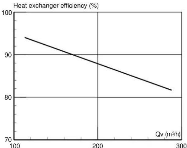
| Heat exchanger efficiency | 94% at 100 m³/h, 88% at 200 m³/h, 82% at 300 m³/h |
| Filtration | G4 filter on fresh air intake, G2 filter on exhaust air outlet |
| Motorized bypass | Integrated, for night cooling (free cooling) |
| Reversibility | Reversible product, interchangeable bypass channel |
| Network connection | Suspension by M8 threaded rods, condensate outlet 15/21 (1/2") with siphon |
| Filter maintenance | Regular inspection, replacement at least once a year |
| Heat exchanger maintenance | Cleaning at least every 2 years with compressed air or vacuum, non-aggressive detergent |
| Safety | Disconnect power before any intervention, magnetic key for unlocking the bypass register |
| Spare parts available | Filters, heat exchanger, bypass register, magnetic key |
| Environmental compliance | End-of-life recycling via WEEE collection points |
Frequently Asked Questions - CADSHE Soler & Palau
User questions about CADSHE Soler & Palau
0 question about this device. Answer the ones you know or ask your own.
Ask a new question about this device
Download the instructions for your Controlled Mechanical Ventilation in PDF format for free! Find your manual CADSHE - Soler & Palau and take your electronic device back in hand. On this page are published all the documents necessary for the use of your device. CADSHE by Soler & Palau.
USER MANUAL CADSHE Soler & Palau
natural_image
Exterior view of a large industrial air duct system with two cylindrical pipes (no text or symbols visible)Manual de instalación. Instrucciones de uso Installation manual. Instructions for use Instructions de montage et d'utilisation Manuale di installazione
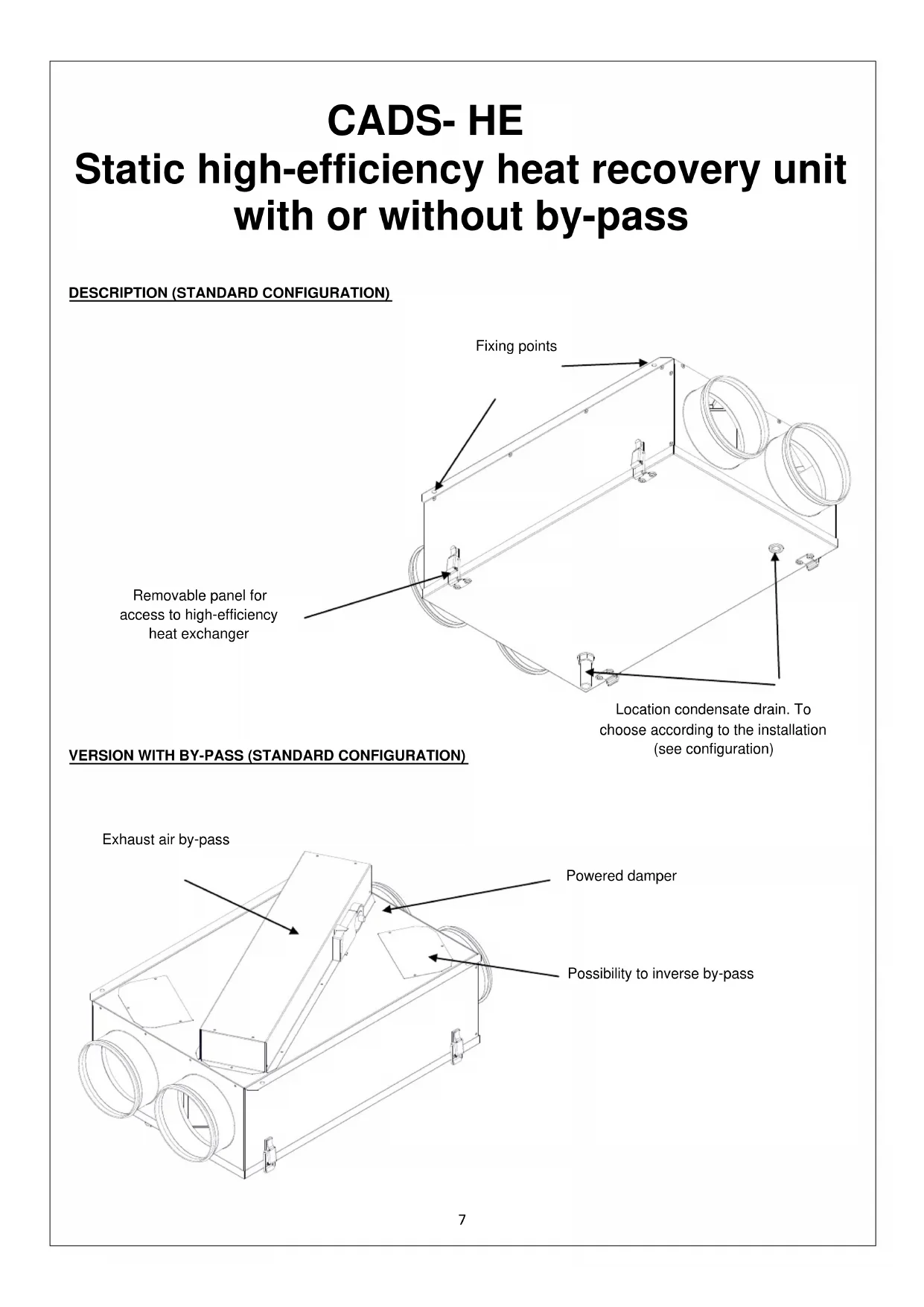
CADS- HE
natural_image
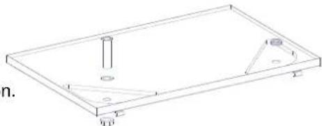
Isometric line drawing of a rectangular frame with internal geometric components (no text or symbols)IMPORTANTE:
Static high-efficiency heat recovery unit with or without by-pass
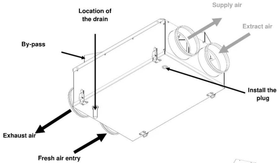
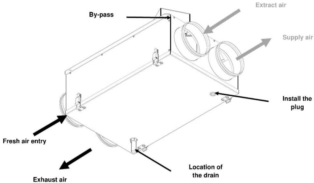
DESCRIPTION (STANDARD CONFIGURATION)
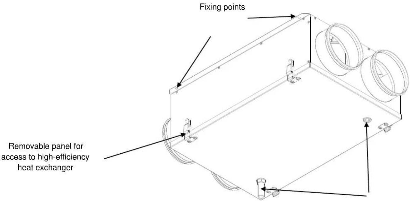
Location condensate drain. To choose according to the installation (see configuration)
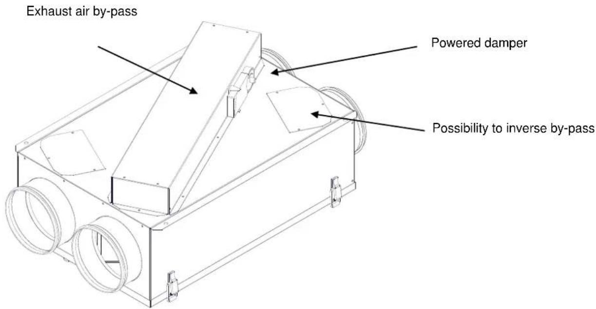
VERSION WITH BY-PASS (STANDARD CONFIGURATION)
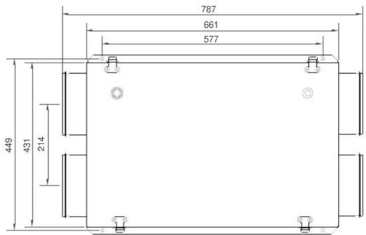
DIMENSIONS
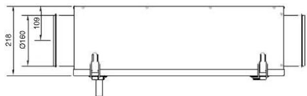
Version without by-pass
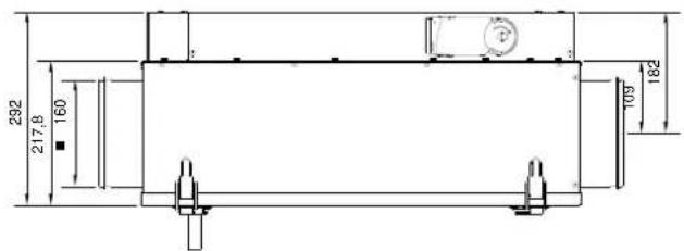
Version with by-pass
CHARACTERISTICS
line
| Qv (m³/h) | Heat exchanger efficiency (%) | | --------- | ----------------------------- | | 100 | 94 | | 200 | 88 | | 300 | 82 |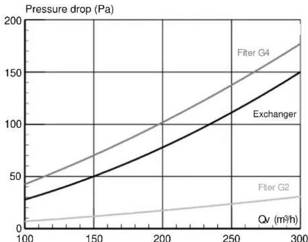
line
| Qv (m³/h) | Filter G4 | Exchanger | Filter G2 | Qv (m³/h) | | --------- | --------- | --------- | --------- | --------- | | 100 | 40 | 30 | 5 | 100 | | 150 | 70 | 50 | 10 | 150 | | 200 | 100 | 80 | 15 | 200 | | 250 | 130 | 110 | 20 | 250 | | 300 | 160 | 150 | 25 | 300 |INSTALLATION
CAD HR S is designed for mounting on the ceiling. The product is provided with fixing points located at the corners of the box. To avoid the condensates returning to the appliance it is necessary to fit a siphon to the condensate evacuation tube.
After placing the equipment in the proper position,
making the connection to the ducts. Connect the drain trap to the cover.
It must be connected to the sewage system (pipe 15/21 (1/2')) by means of a siphon.
Fill the siphon to avoid smells.
natural_image
Pure technical line drawing of a rectangular frame with internal components and no text or symbolsIMPORTANT:
Be sure to check the correct installation of the product (100% horizontal without inclination to ensure a proper condensate drainage.
Important note:
Product is reversible: depending on the network configuration, the product can be reversed (see « Configuration ») as well as the by-pass.
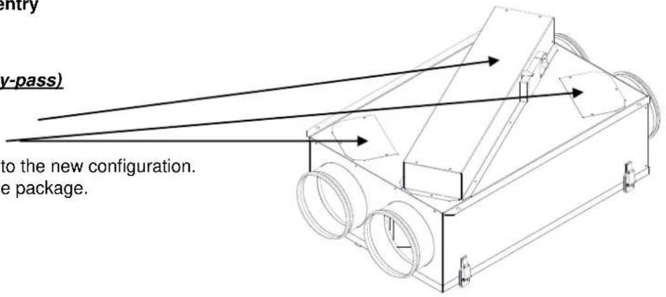
PRODUCT CONFIGURATION
Configuration n°1 (standard configuration)
Configuration n°2 (reverse by-pass)
- Remove the by-pass.
- Remove the 2 covers.
- Place the by-pass according to the new configuration.
• Install 2 covers supplied in the package.
MAINTENANCE
Filters
- Unlock the 4 fasteners on the cover (take care to keep the cover with one hand during this operation to avoid falling by gravity (risk of damage to the cover and risk of injury).
- Remove the cover.
- The filters should be inspected regularly and changed at least once a year.
Exchanger
- Unlock the 4 fasteners on the cover (take care to keep the cover with one hand during this operation to avoid falling by gravity (risk of damage to the cover and risk of injury).
- Remove the cover.
- Remove the metal strip which secure the heat exchanger.
CAUTION: keep the heat exchanger with one hand during this operation to avoid falling by gravity (risk of damage to the heat exchanger and risk of injury).
• Take care not to damage the fins of the heat exchanger.
- The heat exchanger should be inspected regularly and cleaned at least once every 2 years.
- Clean the heat exchanger with compressed air or vacuum cleaner. Use non agressive detergents.
CAD HR S WITH BY-PASS VERSION
Utilisation
The use of by-pass allows take cold night air in summer which can then be used it for during the day. (free cooling)
The control can be either local (eg switch placed in the room of a commercial building or housing in an apartment building) or centrally (eg apartment buildings).
Characteristics
Electrical supply 230 V, I<100 mA Couple 2 N.m.
Intensity < 100 mA Consumption 1.5W
Note : The servomotor has integrated magnet for gear disengagement. Manual override with magnet possible (the gear is disengaged as long as the magnet adheres to the symbol).
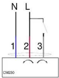
WIRING
Before any intervention, PUT YOUR EQUIPMENT WITH LOW PRESSURE.
- Blue wire No 1 connected to the neutral.
- Brown wire No 2 connected to the phase.
- White wire No 3 zero potential (switch open), the by-pass is closed: the airflow pass through the heat exchanger.
- White wire No 3 connected to the phase (switch closed), the by-pass is open: the airflow doesn't pass through the heat exchanger.
Dealing with products at the end of their life:
To contribute to environmental protecon and opmisao on of natural resources, this product should be recycled at the end of its useful life. It should not be disposed of in a landll or treated as household waste but must be deposited at a collecon point for recycling electrical and electronic equipment. For further informaon about recycling of this product, please contact: the Agency for Environment and Energy Control in your area, your consular chamber (CCI or Chamber of trades and the cras), your municipality, your household waste disposal unit.
Note: to the extent that the equipment sold is professional electrical and electronic equipment covered by Decree No. 2005-829 of 20 July 2005 implementing Directive 2002/96/EC of 27 January 2003, the owner of this equipment will, unless otherwise agreed, fund and organise the waste disposal of this equipment under the conditions denied in Arcles 21 and 22 of the Decree.
CADS- HE
CONFIGURATION DU PRODUIT
CAD HR S AVEC VERSION BY PASS
Utilisation
CADS-HE CON VERSIONE BY-PASS
Uso
- CADS- HE
- IMPORTANTE:
- Static high-efficiency heat recovery unit with or without by-pass
- DIMENSIONS
- CHARACTERISTICS
- INSTALLATION
- IMPORTANT:
- PRODUCT CONFIGURATION
- Configuration n°2 (reverse by-pass)
- MAINTENANCE
- Filters
- Exchanger
- CAD HR S WITH BY-PASS VERSION
- Utilisation
- WIRING
- Dealing with products at the end of their life:
- CONFIGURATION DU PRODUIT
- CAD HR S AVEC VERSION BY PASS
- CADS-HE CON VERSIONE BY-PASS
- Uso
Brand : Soler & Palau
Model : CADSHE
Category : Controlled Mechanical Ventilation