Type S - Water pump Norsup - Free user manual and instructions
Find the device manual for free Type S Norsup in PDF.

| Product type | Water pump (pool filter) |
| Brand | Norsup (NORSUP Pumps) |
| Model | Type S |
| Use | Pool water treatment (filtration and retention of suspended particles) |
| Available flow rates | 6 m³/h, 10 m³/h, 14 m³/h, 22 m³/h, 35 m³/h |
| Accepted filter media | Quartz sand, ground quartz, zeolite, fossil meal, anthracite, activated carbon |
| Grain size of filter media | 0.4 mm to 0.8 mm (sand), others according to datasheet |
| Operating pressure | 1.5 bar (flow rates 6 to 22 m³/h) / 2.5 bar (35 m³/h) |
| Maximum allowable pressure | 4 bars |
| Fluid temperature | +5 °C to +40 °C |
| Ambient operating temperature | +5 °C to +40 °C |
| Storage temperature | 0 °C to +50 °C |
| Valve type | 6-way valve (filtration, backwash, rinse, drain, circulation, closed) |
| Main functions | Filtration, backwash, rinse, drain, circulation, full closure |
| Routine maintenance | Weekly pressure check, backwash, check media level, replacement every 2 years |
| Safety | Do not open under pressure, use PPE (gloves, goggles, shoes), cut power before maintenance |
| Installation | Flat and dry surface, protected from frost and direct sunlight, temperature 5-40 °C |
| Connection | Glued PVC pipe, threaded nuts supplied |
| Standards | Directive 97/23/EC (pressure equipment) |
| Warranty | Void if instructions not followed or unauthorized modifications |
| After-sales service | Contact Norsup, its subsidiary or its dealer |
| Spare parts and repairability | Interventions reserved for qualified personnel; contact Norsup after-sales service |
Frequently Asked Questions - Type S Norsup
User questions about Type S Norsup
0 question about this device. Answer the ones you know or ask your own.
Ask a new question about this device
Download the instructions for your Water pump in PDF format for free! Find your manual Type S - Norsup and take your electronic device back in hand. On this page are published all the documents necessary for the use of your device. Type S by Norsup.
USER MANUAL Type S Norsup
natural_image
Two large industrial water level control vessels with black bands and gauges, shown from different angles (no text or symbols visible)NORSUP

natural_image
Two people swimming in a pool, one with arms extended and the other with hands raised (no text or symbols visible)4
POOL FILTER SYSTEM TYPE S, TYPE T SERIES
ORIGINAL MANUAL
12
SCHWIMMBAD FILTERANLAGE TYP S, TYP T SERIE
POOL FILTER SYSTEM - TYPE S, TYPE T SERIES
CONTENTS:
1 GENERAL PREFERENCE 4
1.1 Identification manufacturer's data 4
2 GLOSSARY OF THE USED TERMS 4
3 RULES OF REFERENCE 4
4 EQUIPMENT DESCRIPTION 4
4.1 Particulars and function 4
4.2 Equipment's overall view 4
4.3 Structural data and technical characteristics 5
4.4 Equipment's technical characteristics 5
5 RISKS CONNECTED TO THE EQUIPMENT 5
5.1 Universality 5
5.2 Connected risks 5
5.3 Risks for an incorrect use 5
5.4 Residual risks 5
6 SIGNS STICKED ON THE EQUIPMENT 6
7 TRANSPORT AND INTERNAL MOVING 6
8 INSTALLATION 6
8.1 Normal working 6
8.2 Storage 6
8.3 Starting 6
8.4 Refilling 6
8.5 Filter closing 7
8.6 Starting 7
8.7 Working 7
8.8 Filtration 7
8.9 Backwash 7
8.10 Rinsing 7
8.11 Waste 7
8.12 Circulation 7
8.13 Lock 8
8.14 Winter 8
9 ORDINARY AND PREVENTIVE MAINTENANCE 8
9.1 Universality 8
9.2 Ordinary maintenance 8
10 DRAINING 8
11 PROHIBITIONS 8
Errors and technical modifications subject to change, reproduction as well as electronic duplication only with our written permission.
© NORSUP Pumps
Edition: 11.2020

natural_image
Two industrial water level control vessels with black bands and gauges, one larger and one smaller, shown against a white background (no text or symbols visible)POOL FILTER SYSTEM - TYPE S, TYPE T SERIES
1 GENERAL PREFERENCE
This user and maintenance handbook is a document issued by NORSUP. It is to be considered an integrated part of the product for its lifetime, even in case of cession to a third party, until its demolition and draining.
All rights of reproduction and spreading of this handbook and of the enclosed documentation, are reserved to NORSUP
The products described in this handbook are patented. Every reproduction, even if it is partial, is forbidden.
The aim of this handbook emitted by NORSUP is to:
- supply operators and maintenance men with all the instructions and warnings necessaries to work safely;
- allow the user to use the equipment in a safe and proper way and to maintain the goods in a state of good efficiency and security;
1.1 IDENTIFICATION MANUFACTURER'S DATA
Declares to be the manufacturer and reference of the equipment for eventual operations of technical maintenance assistance and/or changing of the equipment described in this handbook.
- If the explanations reported here are considered not clear or incomplete and if one or more parts of the handbook are not perfectly comprehensible, it is necessary to address to the manufacturer so as to obtain all the necessary additional indications and/or information.
- The manufacturer engages himself, if necessary, to supply a new handbook enriched with the agreed clarifications.
- In order to obtain the best performance from the products, it is recommended to follow carefully the instructions kept in this handbook, which should be read carefully in every single part.
- The indications concerning the use of the equipment should be executed in an absolute and precise way according to what is specified hereafter. In this way the inconveniences caused by non observance of the rules can be avoided. This handbook is technical, so it is an exclusive property of NORSUP whom reserves all rights; every reproduction of this handbook, even if in part or partial, is forbidden by the law.
ATTENTION

It is not allowed to use the equipment in different configurations from what is reported within or different working installations from what is established and advised by the manufacturer. Different, improper, and/or a non correct use regarding the mentioned instructions of installation and use present in this handbook make all the manufacturer's responsibility no longer valid.
2 GLOSSARY OF THE USED TERMS
We refer to the table enclosed for what concerns the general definitions of the single equipment's components.
It is defined INCORRECT USE the use of the equipment outside the limits specified by this handbook.
Only qualified and authorized staff, competent technicians and installers, are allowed to carry out the following activities:
- installation and start up;
- removal and demolition;
- regulation & setting
- maintenance and repair;
3 RULES OF REFERENCE
A classification of the pressure equipment has been executed according to the 97/23/CE PED directive since it has been submitted to a pressure higher than 0,5 bar.
4 EQUIPMENT DESCRIPTION
4.1 PARTICULARS AND FUNCTION
This equipment is used for the water treatment of the pool for human bathing. The aim is to guarantee the filtration and to keep suspended matter not withheld by the traditional filter baskets installed up stream of the system.
The NORSUP sand filter has been manufactured to hold materials and suspended matter of 0,4 mm and 0,8 mm in size.
The principle of function is that of trapping suspended matter by making the treated water flow through the filtering material situated inside the filter.
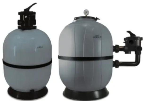
4.2 EQUIPMENT'S OVERALL VIEW
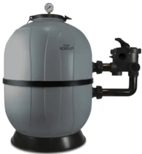
natural_image
Exterior view of a NORUSUF pressure vessel with black tubing and pressure gauge (no text or symbols on the device itself)POOL FILTER SYSTEM - TYPE S, TYPE T SERIES
4.3 STRUCTURAL DATA AND TECHNICAL CHARACTERISTICS
The main indications concerning the equipment's characteristics are given hereafter.
4.4 EQUIPMENT'S TECHNICAL CHARACTERISTICS
The dimensions, the bulkheads, the connection dimensions and the weights of the different filters are reported on the component cards enclosed at the end of this handbook (page 22-23)
Filters should operate only with:
- aqueduct or ground water
- seawater;
- water mixed with sodium hypochlorite in compliance with the UNI 901:2002 rule in a solution of max 0,2 mg/l (2 ppm).
The equipment can be submitted to the working pressure of:
1,5 bar (6-10-14-22 m3/h) 2,5 bar (35 m3/h)
ATTENTION

Before the installation check that the inlet system, connected to the filter, is provided with suitable devices which limit and prevent the overflow of the maximum pressure inside the filtration system (4 bar).
The fluid temperature used by the equipment should be included in the following range:
Tmin: +5°C Tmax: +40°C
ATTENTION

If it is provided that if the fluid temperature can go below the freezing point, isolate the equipment from the inlet system connected to it and empty it, according to the conditions specified in the maintenance section.
5 RISKS CONNECTED TO THE EQUIPMENT
5.1 UNIVERSALITY
For its own conformation, for its structural prerogatives and for the work that should be accomplish, the equipment shows some not eliminable risks hereafter described.
5.2 CONNECTED RISKS
| Refer-ence | Risk Sign Danger location | Remedy | ||
| 1 Fluids' | project-ion |  | Zone surrounding the equipment | sign |
5.3 RISKS FOR AN INCORRECT USE
In addition to the risks presciently underlined, it is possible to suppose that, although it has been indicated more than once how to behave properly to limit the risks, there could be situations of anomalous behaviour (incorrect use).
The risks caused by an incorrect use and their prevention are summarized in the following table.
| Incorrect use | Risk | Prevention |
| Incorrect insertion of the filtering material | Malfunction, saturation of the filtering mass, gas formation | Information on the handbook |
| Not suitable treatment with fluid | Malfunction, saturation of the filtering mass, gas formation | Information on the handbook |
| Treatment of a part or all equipment with chemicals | Weakening and/or structure'slough | Information on the handbook |
| Unstable positioning | Upsetting | Information on the handbook |
| Lid's opening while the equipment is pressurized | flooding, parts projection | Information on the handbook |
5.4 RESIDUAL RISKS
In this way, with the application of what mentioned and arranged, we have prepared a remedy for all kind of not eliminable risks, consequently, there should be no damages. Anyway, the operator should check the absence of people in the risk zone before doing any operation.
The operator should take precautions by wearing the necessaries individual protection means (gloves, glass, anti-noise devices, accident prevention shoes).
POOL FILTER SYSTEM - TYPE S, TYPE T SERIES
6 SIGNS STICKED ON THE EQUIPMENT
The following signs are used inside the handbook and on the machineries:
| SYMBOL | EXPLANATION |
 | Generic danger |
 | Compulsory to protect the respiratory tract |
 | Access prohibited to people not authorized |
 | Compulsory to protect hands with gloves |
 | Compulsory to consult the handbook |
 | Compulsory to remove the electrical connections for the maintenance |
7 TRANSPORT AND INTERNAL MOVING
The following specifications are to be considered: It is recommended the use of qualified and specialized staff to move, transport and install the equipment. Moving should be executed by lifting the equipment according to the following specifications:
by the edge with open lid;
by the base;
For short moving it is possible to use a fork lift and/or manual trolley.
ATTENTION:

Carry out all the operations with caution AND RISE THE EQUIPMENT BY FOLLOWING THE INDICATED ZONE
ATTENTION:

It is necessary to follow the instructions reported in this handbook to rise and to move the equipment.
8 INSTALLATION
8.1 NORMAL WORKING
Connection should be executed by authorized and qualified staff. Equipment's connection should be linked to the pool system circuit. Connection should be done by using threaded pipes union which are included in the equipment, the thread and the diameter are indicated in the components card.
Pipe union exit, included in the equipment, should be connected by a glued smooth pipe (PVC) During the normal working, the equipment should be placed in a covered and dry area protected from the direct sunlight irradiation and from heat.
For proper working conditions, the water temperature should range between +5°C and +40°C. The filter has a flow stream direction – which should be respected – these are indicated by the arrows situated near the pipe unions.
8.2 STORAGE
During an eventual storage the equipment should be kept in a covered and dry place. The equipment should be protected from eventual water sprinklings, dust, humidity, collision or accidental damages.
Advisable room temperature should be included between 0°C and +50°C.
8.3 STARTING
Check carefully that the components aren't damaged because of transport collisions. If any part is damaged or it is not in keeping with the original condition of supplying, don't make the system work and provide for the reparation or for the substitution at the assistance centre.
Check that all the filter connection pipes and the valves are closed.
8.4 REFILLING
Refill the filter by putting in the filtering material from the hole lid.
The Filter media sand used must have the following characteristics:
| FILTER MEDIA GRANULOMETRY | |
| QUARTZ SAND and 1 ÷ MILLED QUARTZ | 0,4 ÷ 0,8 mm |
| 2 mm | |
| 1 ÷ 3 mm | |
| 3 ÷ 6 mm | |
| ZEOLITE | 1 ÷ 2,5 mm |
| 2,5 ÷ 5 mm | |
| DIATOMACEOUS | - |
| ANTHRACITE | 0,8 ÷ 1,8 mm |
| ACTIVATED CARBON | - |
POOL FILTER SYSTEM - TYPE S, TYPE T SERIES
ATTENTION:

Before refilling close the access hole of the centre manifold pipe which is placed just under lid. Remove the gasket from the filter's entry.
| FILTER MODEL | MATERIAL QUANTITY |
| 6 m3/h | 75 Kg |
| 10 m3/h | 100 Kg |
| 14 m3/h | 150 Kg |
| 22 m3/h | 250 Kg |
| 35 m3/h | 550 Kg |
ATTENTION:

At the end of the refill remove the closure used for the manifold pipe which is placed under the lid.
Afterwards fill the sand filter with water.
The refill should be done slowly by letting the water flow in every interstices inside the filtering material. Refill should be done until the water level overflows the filter's edge.
ATTENTION:

Check that the spreading of the water in excess doesn't cause damages and that there aren't any nearby voltage and/or electric component parts present were the excess water could be in contact with.
8.5 FILTER CLOSING
- Close the filter by the lid, the gasket, the clamp, the screws and the nuts included in the equipment
- Verify that the contact surfaces are clean and eventually remove the dirt or the residual filtering material;
- Place the gasket on the filter.
- Assemble the pressure gauge on the lid in the proper hole (by the threaded hole or by the proper back nut and O-ring);
- Place the lid
- Put the clamp to close the lid and the filter top
- Place the 2 nuts in the clamp
- Close the clamp using the screws, until the two side are coincident. Do not over-screw!
8.6 STARTING
Open slowly the valves situated on the connection pipe. Check that there are no water leaks.
ATTENTION:

In case of water leaks, close immediately the filter valves and proceed with an examination of the system.
8.7 WORKING
The equipment carries out the filtration of the water according to what is described in this handbook. For a good performance of the filter and for a good management of the system connected to it, there are further functions that should be considered and suggested.
By a different set up of the multi-port valve connected to the filter (when models are included) it is possible to carry out these other functions.
A 6 way valve has the following main working positions:
1 filtration 4 waste
2 backwash 5 circulation
3 rinsing 6 lock
The operating conditions of each position are described in detail hereafter.
ATTENTION:

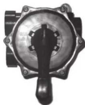
natural_image
Close-up of a mechanical component with a central knob and flanged ends (no visible text or symbols)The selection with the multiport valve level should be done ONLY WHEN THE SYSTEM IS SWITCHED OFF AND NOT IN USE!
8.8 FILTRATION
It is the normal position of exercise, it carries out the filtration of the treated water from the entry to the exit.
8.9 BACKWASH
It is used for cleaning the filter media present in the filter. This operation removes any suspended matter caught by the filter media during normal exercise.
8.10 RINSING
it should be done after the backwash in order to remove eventual impurities inside the valve.
8.11 WASTE
It allows water to flow straight to the waste (ex. emptying the pool)
8.12 CIRCULATION
It allows the system to operate without the filter. water is by-passed straight to the exit.
POOL FILTER SYSTEM - TYPE S, TYPE T SERIES
8.13 LOCK
It closes every passage of the valve.
8.14 WINTER
It is an intermediate position which, with an empty system, prevents eventual breakings caused by freezing.
9 ORDINARY AND PREVENTIVE MAINTENANCE
9.1 UNIVERSALITY
The handling of the following operations is left to the user. They also can be executed (on request) by NORSUP.
If the user intends to do the maintenance by himself, the operations should be entrusted to a qualified person able to estimate an eventual fault and restore the protections and the securities. Maintenance operations, search for faults and repairs are allowed only to qualified staff; non authorized operations make the warranty void.
9.2 ORDINARY MAINTENANCE
Equipment's maintenance is based on a sequence of operations which, if done as indicated hereafter, allows to keep the equipment in perfect working efficiency. Maintenance should be done according to the rules indicated in this handbook.
The indicated control and maintenance slots are to be considered indicative values for the exercise in normal conditions, on the base of general use of 8 hours a day for 365 days a year. (approx. 3,000 hours/years). Different conditions can change the maintenance's slot.
ATTENTION:

During the emptying of the filter, check that the spreading of the water in excess doesn't cause damages and that there aren't any nearby voltage and/or electric component parts present were the excess water could be in contact with.
10 DRAINING
The material's waste should be done in accordance to the governing laws in force in the country where the equipment has been installed. A waste separation should be done when a partial or complete draining is executed.
11 PROHIBITIONS
ATTENTION:


It is not allowed to
• Install the equipment on an uneven horizontal surface
• Install accessories not authorized by NORSUP;
- Use the equipment for operations not described in this handbook;
- Use the equipment for pressure or performances higher than what mentioned in this handbook.
- Allow non qualified and non trained staff to use the equipment;
• Non use of protection;
- Change the equipment's original parts.
The main operations are summarized hereafter:
| Work to be carried out | Materials Daily Weekly Monthly | Every 3 months | Every 6 months | Yearly | Every 2 years | More Note | |||
| Pressure control | Mano-meter |  | Pressure should be lower than 1 bar. If it is higher than 0,5 bar do the backwash | ||||||
| Back-wash | Multi-port valve position 2 | × | Cycle time max. 5 min. (check the clearness of the multiport valve's lass) | ||||||
| Filtering sand level | Eventually refill with material until half of the filter's high |  | Select the filter from the system, empty it by un-screwing the closing plug situated in the lower part and remove the lid. At the end screw the drain plug. | ||||||
| Filtering material's replacement | Filtering material |  | |||||||
POOL FILTER SYSTEM - TYPE S, TYPE T SERIES
All the operations made on the filter should be reported on the enclosed book.
| Installation's DateAnd Seller' Stamp | FILTER CARD | User | |
| Model Seriel N. Operator | |||
EXAMINATION OPERATION and MAINTENANCE BOOK
| Number List | Activities's Description Checks And Maintenance | Kind Of Maintenance Ord. Extra. Ver. | Note | Maint- enance Date | Hours Spent | Next Maint- enance Date | Sign | ||
| 1 | |||||||||
| 2 | |||||||||
| 3 | |||||||||
| 4 | |||||||||
| 5 | |||||||||
| 6 | |||||||||
| 7 | |||||||||
| 8 | |||||||||
| 9 | |||||||||
| 10 | |||||||||
| 11 | |||||||||
| 12 | |||||||||
| 13 | |||||||||
| 14 | |||||||||
| 15 | |||||||||
NORSUP SAND FILTERS - TYPE S, TYPE T SERIES
INHALTSVERZEICHNIS:
1 ALLGEMEINE INFORMATIONEN 11
2 INSTALLATION 11
3 OPERATION 11
4FILTERBETRIEB 11
natural_image
Two industrial water filter units with black bands and control valves, one larger and one smaller, shown against a white background (no text or symbols visible)NORSUP SAND FILTERS – TYPE S, TYPE T SERIES
1 ALLGEMEINE INFORMATIONEN
natural_image
Two large industrial water filter units with black bands and control valves, one with a valve and the other with a pressure gauge (no visible text or symbols)SYSTÈME DE FILTRE DE PISCINE – TYPE S, TYPE T SÉRIE
es opportuném
1 AVANT-PROPOS GÉNÉRAL
natural_image
Exterior view of a NORUP water level control unit with black tubing and pressure gauge (no text or symbols on the device itself)SYSTÈME DE FILTRE DE PISCINE - TYPE S, TYPE T SÉRIE
4.3 DONNEES DE CONSTRUCTION ET CARACTERISTIQUES TECHNIQUES
5.3 RISQUES DUS A L'UTILISATION INCORRECTE PREVISIBLE
5.4 RISQUES RESIDUELS
7 TRANSPORT ET MANUTENTION INTERNE
8.1 INDICATIONS GENERALES
natural_image
Close-up of a mechanical component with a central handle and flanged ends (no visible text or symbols)natural_image
Close-up of human feet and legs standing on a blue water surface, no text or symbols visibleNOTES / NOTIZEN / COMMENTAIRES
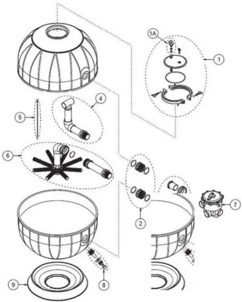
COMPONENTS CARD
| N° Codice/Code MOD. Descrizione / Description | |||
| 1 | 100100980 6-10-14 | Kit Cover Aquarius Filter 6-10-14 Mc Cov. Beige Ral9001 | |
| 100100990 22-35 Kit Cover Aquarius | Filter 6-10-14 Mc Cov. Beige Ral9001 | ||
| 1A 10 | 0101R01 6-10-14-22-35 Kit Manometer Aquarius Filter | ||
| 2 | 100101R08 6-10-14 Kit Double Connection In-Out Aquarius Filters 6-10-14 Mc/H | ||
| 100101R09 22-35 Kit Double Connection In-Out Aquarius Filters 22-35 Mc/H | |||
| 3 | 100100926 | 6-10-14 | Kit Out For Lateral Valve Aquarius Filters 6-10-14 |
| 100100934 | 22-35 | Kit Out For Lateral Valve Aquarius Filters 22-35 | |
| 4 | 100100966 | 6 | Kit Upper Pipes Aquarius Filter 6Mc/H |
| 100100928 | 10 | Kit Upper Pipes Aquarius Filter 10Mc/H | |
| 100100930 | 14 | Kit Upper Pipes Aquarius Filter 14Mc/H | |
| 100100932 | 22 | Kit Upper Pipes Aquarius Filter 22Mc/H | |
| 100100128 | 35 | Kit Upper Pipes Aquarius Filter 35Mc/H | |
| 5 | 100101R24 | 6-10-14-22-35 | Kit Tube-Fisseres Air Discharge Aquarius Filter |
| 6 | 100100965 | 6 | Kit Lower Pipes Aquarius Filter 6Mc/H |
| 100100927 | 10 | Kit Lower Pipes Aquarius Filter 10Mc/H | |
| 100100929 | 14 | Kit Lower Pipes Aquarius Filter 14Mc/H | |
| 100100931 | 22 | Kit Lower Pipes Aquarius Filter 22Mc/H | |
| 100100127 | 35 | Kit Lower Pipes Aquarius Filter 35Mc/H | |
| 7 | 100100483 | 6-10-14 | Abs Valve Connection 1"1/2 Lateral Command, Black |
| 100100484 | 22-35 | Abs Valve Connection 2" Lateral Command, Black | |
| 8 | 100101R19 | 6-10-14-22-35 | Kit Out Water Aquarius Filter |
| 9 | S9010200 | 6-10-14 Base | Sand Filter Aquarius |
| S9010240 | 22 | Base Sand Filter Aquarius 22Mc/H | |
| S9010790 | 35 | Base Sand Filter Aquarius 35Mc/H | |
COMPONENTS CARD
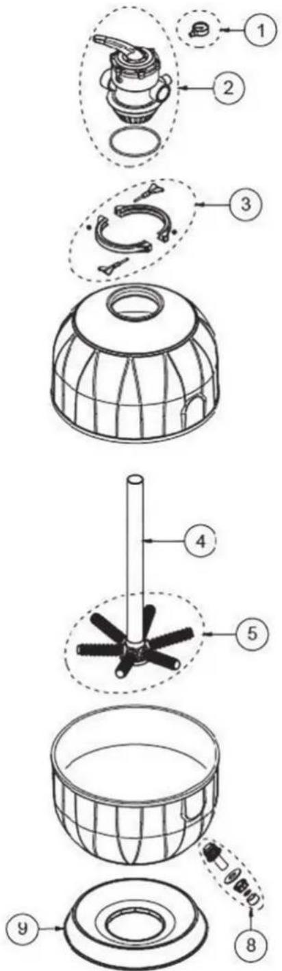
| N° Codice/Code MOD. Descrizione / Description | |||
| 1 | AB060090 6-10-14 | Manometer Radial Attack Aquarius | |
| 100100583 6-10-14 | Abs Valve Connection 1"1/2 Top Command, Black | ||
| 3 | 100101R04 | 6-10-14 | Closing Clampwith Screws-Nut For Aquarius 6-10-14 Mc/H |
| A6 | 070400 6 Black Pvc | Pipe Dn50 Sp.3 | H450 Mm For Filter 6 Mc Top |
| 4 | A6070290 10 Black Pvc | Pipe Dn50 Sp.3 | H595 Mm For Filter 10 Mc Top |
| A6 | 070280 14 Black Pvc | Pipe Dn50 Sp.3 | H625 Mm For Filter 14 Mc Top |
| 5 | 100101R25 | 6-10-14 | Kit Collector+Glow Aquarius Filter 6-10-14 Mc/H |
| 8 | 100101R19 | 6-10-14 | Kit Out Water Aquarius Filter |
| 9 | S9010200 | 6-10-14 Base | Sand Filter Aquarius |

natural_image
Close-up of a transparent blue water surface with subtle reflections and splashes (no text or symbols)NORSUP