RolloTube Comfort RTCM - Electric motor RADEMACHER - Free user manual and instructions
Find the device manual for free RolloTube Comfort RTCM RADEMACHER in PDF.
| Product Type | Tubular motor for roller shutters |
| Brand | RADEMACHER |
| Model | RolloTube Comfort RTCM |
| Dimensions (L x diameter) | 462 to 524 mm x 35 to 45 mm (depending on version) |
| Weight | Approx. 5 kg |
| Power supply | 230 V / 50 Hz, single-phase |
| Power consumption | 121 to 198 W depending on torque |
| Rated current | 0.53 to 0.86 A |
| Maximum torque | 6 to 40 Nm depending on version |
| Rotation speed | 16 rpm |
| Protection rating | IP44 |
| Main functions | Up/down, electronic limit switch adjustment, automatic obstacle stop, thermal protection |
| Electrical connection | 3 m cable, 0.75 mm² cross-section, 5 wires |
| Maintenance and cleaning | Clean with a dry cloth; regularly check proper operation and balancing |
| Safety | Installation by a qualified electrician; disconnect before any intervention; comply with DIN VDE 0100 standards; thermal protection and obstacle stop |
| Spare parts and repairability | Adapter, drive, tip, fixing springs, bearing, cable; repair by authorized service center |
| Warranty | 60 months (5 years) on manufacturing defects, subject to proper installation |
| General information | Use prohibited for outdoor blinds without supervision; do not use in frost; intermittent duty max 4 min |
Frequently Asked Questions - RolloTube Comfort RTCM RADEMACHER
User questions about RolloTube Comfort RTCM RADEMACHER
0 question about this device. Answer the ones you know or ask your own.
Ask a new question about this device
Download the instructions for your Electric motor in PDF format for free! Find your manual RolloTube Comfort RTCM - RADEMACHER and take your electronic device back in hand. On this page are published all the documents necessary for the use of your device. RolloTube Comfort RTCM by RADEMACHER.
USER MANUAL RolloTube Comfort RTCM RADEMACHER
General safety instructions. 46
Correct use 47
Important installation instructions 47
Installing the tubular motor 48
48
Determining the length of the winding shaft. 48
Assembling/disassembling the adapter and the driver 48
Pushing the tubular motor into the winding shaft 49
Preparatory work when using precision tubes 49
Attaching the roller cap 50
Inserting the motor into the bearings 51
Assembling the shutter curtain 51
Safety instructions for electrical connections 52
Electrical connection of the tubular motor 53
Switching several tubular motors in parallel 53
Connecting an external button 54
Using the setting wire. 54
Connecting a corded switch-setting device. 54
Adjusting the limit stops 55
Emergency shut-down. 56
What do I do if...? 56
Technical data 57
CE Mark and EC Conformity 57
Guarantee conditions 72
NL

RolloTube Comfort Small
RolloTube Comfort Medium
(e) PE grun/gelb
(f) = N blau
(g) = L1 schwarz
(h) = (▲) schwarz
(i) = (▼) brown
f = 1 weif (Setzleitung)
(k) = externer Taster
WICHTIG
Faktor: = 86
= (2,1s× 86 = 180,6s)


RolloTube Comfort Small

RolloTube Comfort Medium
2004/108/CE Directiva CEM
RolloTube Comfort Small

RolloTube Comfort Medium
Service intermittent
2006/42/CE Directive machines
...with your purchase of this tubular motor, you have decided for a quality product manufactured by RADEMACHER. We would like to thank you for your confidence.
The new RADEMACHER tubular motors have been designed in an effort to the greatest possible ease of operation. With uncompromising quality requirements, after extensive test series, we are proud to present this innovative product to you.
All of our highly qualified staff at RADEMACHER stand behind this product.

CE Mark and Conformity
This present product complies with the requirements of the applicable european and national directives.
The conformity has been proved and the corresponding declarations and documentation are available on file at the manufacturer's premises.
i
These instructions...

...describe how to install, connect and operate series RolloTube Comfort RADEMACHER tubular motors.
Before you begin work, please read these instructions all the way through and follow all of the safety instructions.
Please save these instructions and give them to any future owners.
For damage resulting from noncompliance with these instructions and safety instructions, the guarantee is void. We assume no liability for any consequent damage.
#
Key to Symbols

Danger of fatal electric shock
This sign warns of danger when working on electrical connections, components etc. It requires that safety precautions be taken to protect the health and life of the person concerned.

This concerns your safety
Please pay particular attention to and carefully follow all instructions with this symbol.

This symbol advises of malpractices that can cause damage to people and property.
NOTE/IMPORTANT/CAUTION
This is to draw your attention to information which works is important to ensure trouble-free operation.

There is always danger of a potentially fatal electric shock when working with electrical systems.
The tubular motor must only be connected to and all work performed on electrical equipment must only be carried out by a qualified electrician in accordance with the diagrams provided in these instruction (see pages 52/53/54).
Carry out the installation and connection with all devices disconnected from the mains.

Non-observance can cause danger to life! Observe installation instructions for installation in damp rooms.
Please observe regulation DIN VDE 01000, part 701 and 702 in particular when using the motor in damp rooms. These regulations detail mandatory safety measures.

Use of a defective device can endanger people and equipment (electrical shock, short circuit).
Never use defect or damaged devices.
Please make sure that the drive and mains cable are free from damage.
Please notify our customer service department (see page 72) of any faults/ damage on the device.

According to the standard DIN EN 13659, care must be taken that the sliding conditions stipulated in EN 12-045 for the hangings are adhered to.
When unrolled, the movement must be at least 40mm at the lower edge with an upward force of 150 N.
Particular care must be taken here to ensure that the outward running speed of the hanging is less than 0.2m / s over the last 0.4m of travel.

Improper use increases risk of injury.
Please instruct all people concerned in the safe use of the tubular motor.
Prohibit children from playing with stationary control units.
Prevent persons with limited abilities or children from playing with fixed controllers or with the remote control.
Roller shutters:
Always monitor roller shutters while they are moving and keep people at a distance until movement has finished.
When cleaning the roller shutter, the equipment must always be at zero voltage.
For owing structures that can be operated outside your range of vision:
Do not operate the owning if any work is being carried out in its immediate proximity (e.g. window cleaning).
For automatically operated awnings:
Disconnect the owing from the mains when performing work in its immediate proximity.
Servicing awnings regularly increases their operating safety.
Please inspect the owing regularly for defective balance and damage to cables and springs.
Damaged ownings must only be repaired by specialists.
General View (Figure ①)
(1) Counter bearing
(2) Ball bearing
(3) Axle of the roller cap
(4) Roller cap
(5) Winding shaft
(6) Tie
(7) Securing clip
(8) Driver
(9) Tubular motor
(10) Adapter
(11) Set button
(12) Drive head
(13) Drive end bearing
(14) Fixing bracket
(15) Motor cable
(16) Control device (e.g. Troll C50)
(17) Roller shutter curtain
(18) Limit ring
(19) Gearbox output shaft
(20) Hanging brackets
Please note:
Customer-specific supply package
Please compare:
The contents of the package with the content description on the packaging after unwrapping it.
The motor designation with the relevant information included on the type plate.
Tubular motors are intended solely for raising and lowering shutters and awnings
IMPORTANT
The motor cable inside the empty tube must be laid up to the distribution box under consideration of local building and electricity regulations.
Only use original manufacturer's parts and accessories.
Operating conditions
The electrical connection equires a permanent 230V / 50Hz power supply at the site of installation as well as an on-site isolating device (fuse).
Important installation instructions
IMPORTANT
Please compare the voltage/frequency specifications on the type plate with those of your local power supply network before installation.

It is vital that the winding shaft is fitted horizontally!
Disassemble or deactivate all cables and equipment that will not be needed for operation before installing the tubular motor.
The moving parts of drives that are operated at less than 2.5m height from the floor must be protected.
If the tubular motor is controlled with a preset OFF switch this switch must be fitted within view of the tubular motor, at a minimum height of 1.5m and away from moving parts.
It is vital that the roller shutter is wound up evenly, as this could otherwise cause damage to the motor and shutter.
The roller shutter box cover must be easily accessible and removable.
Do not disassemble the mechanical stoppers on the last shutter slot.
For automatically operated awnings:
Awnings must be fitted in such a way that there is a minimum distance of 0.4m between the owing and objects in its immediate proximity when it is fully extended.
The lowest point of any awining system must not be less than 1.8m high.
NOTE
The following installation instructions apply to RADEMACHER tubular motors and accessories used in standard installation conditions only.
The drive head (12) of the motor can be installed on either the left or right side of the roller shutter box. These instructions detail how to install the drive head on the right side.
Necessary minimum roller shutter box width:
Tubular motor series:
Medium
Minimum width, approx.:
cm 67 cm

Installing the bearings (Figure ②)
1. Please check the position of the drive end (13) and counter bearing (1) in the roller shutter box before commencing any work.
Wind the entire shutter curtain onto the winding shaft and measure diameter D. For determining the position of the bearing's centre in relation to the guide rail see figure ②.
IMPORTANT
Once fully wound up, the installed roller shutter must enter the window's guide rail vertically.
2.
Install the bearings in accordance with the bearing type and conditions on site.
Install the drive end bearing (13) in such a way that the set button (11) can be reached easily later on and the motor cable can be laid without having to bend it.
Make sure that the bearings are installed horizontally. Roller shutters that are not wound up straight can cause damage to and destroy the drive.

Determining the length of the winding shaft (Figure ③)

B = Counter bearing/roller cap
C = Drive end bearing/motor
-
Measure the distance between the wall and the drive end (13) - and counter bearing (1) as shown.
-
Measure the roller shutter box and determine the required shaft length (L).
Length of the winding shaft: L = A - (B + C)
- Trim the winding shaft (5) to the required length.
Cut the shaft to length at a right angle using a hacksaw. Debrr the inside and outside of the shaft using a file.

Assembling/disassembling the adapter and the driver (Figure 4)
1. Assembling the adapter (10)
Push the adapter (10) over the limit ring (18) at the motor head until it clicks into place. Ensure that the notch in the adapter (10) is positioned correctly.
2. Disassembling the adapter (10)
Press both of the securing springs on the limit ring (18) down and pull the adapter (10) off the limit ring (18).
- Assembling the driver (8)
Push the driver (8) on to the gearbox output shaft (19) as far as it will go and fix it in place using the securing clip (7) provided.
- Disassembling the driver (8)
Remove the securing clip (7) from the gearbox output shaft (19) and then remove the driver (8).


Do not push the motor (9) into the winding shaft (5) using force.
This could destroy the motor.
1. First, push the driver (8) into the winding shaft (5)
IMPORTANT
When installing winding shafts such that the rabbit is on the inside, it must be ensured that the motor (9) has sufficient free space.
2. Then push the winding shaft (5) onto the adapter (10).
IMPORTANT
Make sure that the adapter (10) does not slide off the limit ring (18) on the motor head (12) during assembly as this can cause malfunction, see page 56.

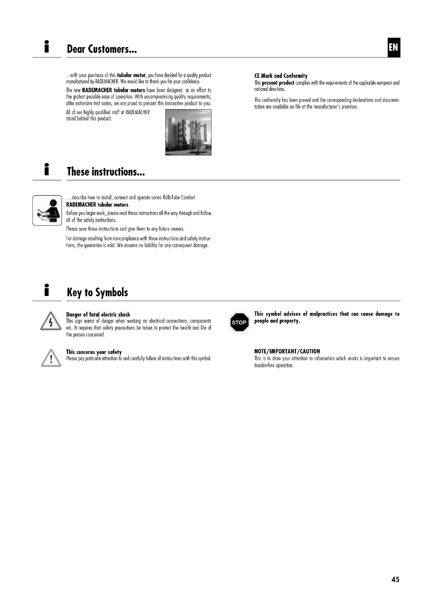
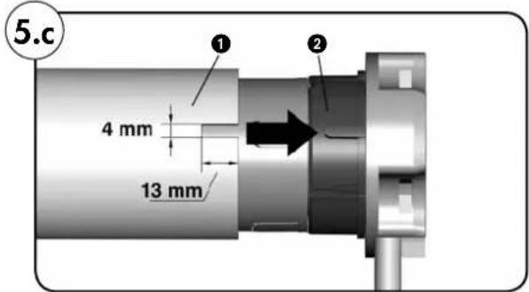
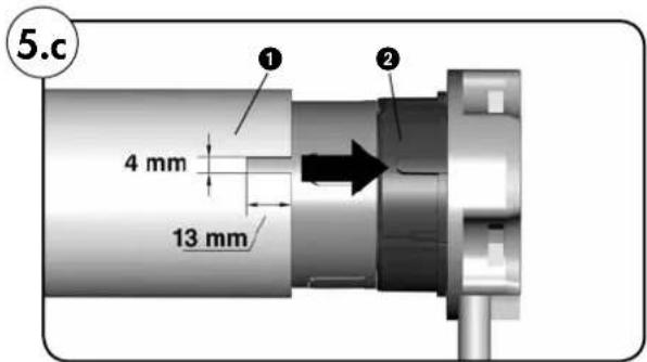
Preparatory work when using precision tubes (Figures 5. - 5f)
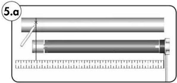

RolloTube Comfort Small

RolloTube Comfort Medium
- Measure the distance between the adapter and the rear third of the driver and mark this distance on the precision tube.
2. Saw a notch 1 at the end of the precision tube so that the raised part 2 of the adapter can be pushed fully into the tube.
NOTE
There must be no play between the notch 1 and the raised part 2.
The dimensions of the notch depend on the type of tubular motor, see figures.


-
Push the tubular motor into the precision tube.
-
Mark four fixing holes and drill these through the precision tube into the driver.
CAUTION
Never drill deeper than 10~mm into the driver.
Never drill close to the drive as this will cause it to malfunction.
- Screw fix or rivet the precision tube to the driver.. ..using self-tapping screws or four blind rivets.

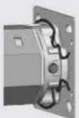
Attaching the roller cap (Figure 5)
- Push the roller cap (4) into the winding shaft (5) and then put the ball bearing (2) onto the axle (3).
1.
Drive end bearing (click bearings)/(13)
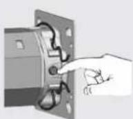
Push the drive head (12) gently into the drive end bearing (13) until it clicks into place.
NOTE
The set button (11) must be easily accessible.
The tubular motors can be installed in 4 positions in the click bearings (13). By opening the fixing brackets (14), you can release the motors from the new click bearing (13) at any time.
Drive end bearing (all other bearing types)
Insert the drive head (12) into the respective drive end bearing and secure it accordingly using a linchpin.
2.
Counter bearing (1)
Insert the other end of the winding shaft (5) with the ball bearing (2) into the counter bearing (1).
In case of using a different drive end bearing than the RADEMACHER click bearing, you need to secure the drive if need be with a second linchpin.
3.
Minor inside width in-accuracies can be corrected by pulling the roller cap (4) further out or pushing it further into the winding shaft (5).
IMPORTANT
Secure the roller cap (4) with a screw once installation is completed.
At least 2/3 of the roller cap (4) must be located inside the winding shaft (5).

Assembling the shutter curtain (Figure ⑦/⑧)
Attach the shutter curtain (17) to the winding shaft (5) using the ties (6) (accessories).


Never drill holes or use screws near the drive when installing roller shutters.
- Push the ties (6) onto the top slot of the roller shutter curtain (17).
- Insert a tie (6) every 40 cm into one of the rectangular openings on the winding shaft (5).
2.a When using SW40 winding shafts (with exterior rabbet), use hanging brackets (20) for attaching the ties (6); see figure 8.

All work with electrical systems is endangered by electric shocks which can be fatal.
The tubular motor must only be connected to the mains and all work on electrical equipment must only be carried out by a qualified electrician in accordance with the diagrams provided in these instructions.
Disconnect all poles of the mains cable from the mains and prevent them from being switched on again.
Check that the system has zero potential.
Carry out all installation and connection works with all devices disconnected from the mains.

There is a danger of short circuit if the cable is damaged.
Make sure that all cables inside the roller shutter box are laid in such a way that they cannot be damaged by moving parts.
Only connect the mains cable for this drive to a similar type of cable. If in doubt, contact our Customer Service department.
In the case of stationary devices ...
...an energy isolating device must be provided for each phase during installation in accordance with VDE 0700. Energy isolating devices include switches with a contact opening gap of at least 3mm (e.g. circuit breaker, fuses or residual current circuit breakers).

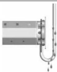
Short circuit danger due to water if cables are not laid correctly.
Never lay the connecting cable (15) vertically upwards from the motor, or water may run down the cable and into the motor, rendering it inoperable. Route the cable in a loop. This allows the water to collect at the lowest point of the loop and drip down from there.


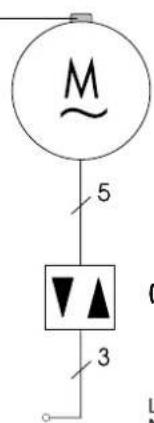
The motor cable (Figure 9)
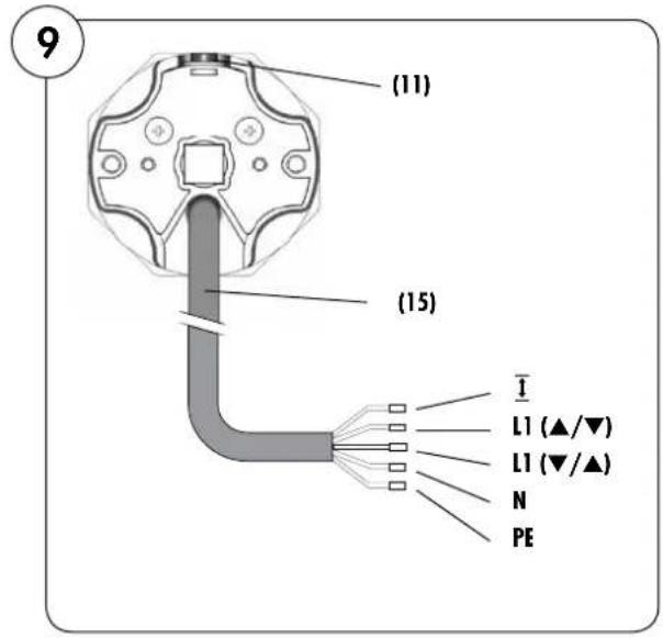
1.
Insert the motor cable (15) into the distribution or switch box intended for this purpose.
Motor cable (15) colour code
I = Setting wire (white)
L1 = Direction of rotation 1 (black)
L1 = Direction of rotation 2 (brown)
N = Neutral
PE = Earth connecting (gre
(11) Set button on tubular motor
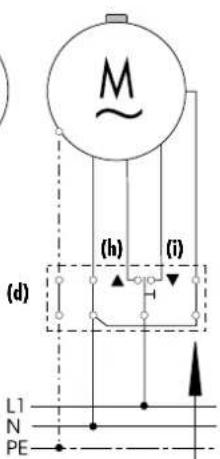
Controlling a drive from one particular location using a single-pole switch/button
10
(a)
(e) (f) (g)
(1)
Key
(a) = Set button (11)
(b) = Control device (e.g. single-pole switch/button)
(c) = Main 230 V/50 Hz
(d) = Switch box
Terminal configuration
(e) PE green/yellow
(f) = N blue
(g) -L1 black
(h) = (▲) black
(i) = (▼) brown
(j)= white(Settingwire)
IMPORTANT
The setting wire (j) must be connected to the neutral conductor (f) once the limit stops have been adjusted.

Switching several tubular motors in parallel (Figure ⑪)
Installation example
11

You can switch several RADEMACHER tubular motors in parallel. The number of motors that can be switched in parallel depends on the capacity of the switch and the fuse being used.
NOTE
When using parallel switching, the motors cannot be controlled on an individual basis anymore.
Adjusting the limit stops
When using parallel switching, the limit stops of each motor must be adjusted individually. To do so, the setting wire of each of the tubular motors must be easily accessible.
IMPORTANT
Because of this, it is important that the setting wire (j) of each of the tubular motors is guided to the relevant distribution box. This ensures that the limit stops can be re-adjusted at any time.
Parallel switching using shutter switches or shutter buttons
You can switch up to 5 motors in parallel using RADEMACHER shutter switches or shutter buttons.
Parallel switching using RADEMACHER control devices (e.g. Troll Comfort)
Number of parallel switchable tubular motors, see Technical data.
Key
(a) Distribution box
(b) = Control device (e.g. single-pole switch/button)
(c) = Mains 230 V/50 Hz
... for the subsequent adjustment the limit stops

Key
(a) = Set button (11)
(b) = Control device (e.g. single-pole switch/button)
(c) = Main 230 V/50 Hz
(d) = Switch box
Terminal configuration
(e) PE green/yellow
(f) = N blue
(g) = L1 block
(h) (▲) black
(i) = (▼) brown
(20 f) = white(Settingwire)
(k) external button
IMPORTANT
Disconnect the external button again once the limit stops have been adjusted and connect the setting wire (j) to the neutral conductor (f), see figure 10.

Using the setting wire
The setting wire is used to transfer the motor set button function to the outside. If the setting wire is connected to an external button (see above), this external button can be used as a set button for adjusting the limit stops.
Guide the setting wire (j) of the motor cable (15) to the respective switch (e.g. to the switch box).

Using the setting wire (j) when installing the device for the first time When installed for the very first time, the roller shutter fitter can connect the entire motor supply cable to a switch setting device (21) which can then be used to adjust the tubular motor limit stops.
Using the setting wire (j) to change the limit stops retrospectively: If you want to change the limit stops of an existing roller shutter installation, all your electrician needs to do is to connect the setting wire (j) to a conventional external switch (230V / 50Hz) in accordance with the connection diagram (12). This switch can then be used in conjunction with your shutter control device to change the limit stops.
Using the setting wire (j) after having adjusted the limit stops: Once the limit stops have been adjusted, the relevant external switching device must be disconnected and the motor must be connected again in accordance with the connection diagram, see figure 10.
IMPORTANT The setting wire (j) must be connected to the neutral conductor (f) once the limit stops have been adjusted.

Connecting a corded switch-setting device
Adjusting the end points before connecting the wires
If you want to adjust the end points of the tubular motor before connecting the wires, you can do so using a corded switch-setting device (21) (available from specialist shops).
Pulling off the motor cable (15) can pose a risk to life.
Make sure that the motor cable (15) is not taken up or pulled off by the winding shaft (5) while making adjustments.
1.
Open the terminal clamp by pressing the lifter and connect all of the tubular motor cable cores according to their functions, see figure 9.
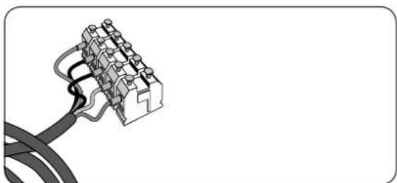
IMPORTANT
You have to set limit stops for both directions of travel, UP () /DOWN () , at which the motor turns off.
The tubular motor has been fully installed.
Do not disassemble the mechanical stoppers on the last shutter slot.
The roller shutter box must be open and the set button (11) on the tubular motor must be easily accessible.

Working with an open roller shutter box is associated with a hand- crush hazard.
Never reach into the winding shaft when the motor is running.
Button assignment at the switch setting device (21)

Set button

Direction of travel ( /)
Initial installation
When installing a shutter and motor for the first time, the roller shutter fitter can adjust the limit stops with the aid of the set button (11) on the motor or by using a conventional switch-setting device (21).
Please refer to the switch-setting device's operating instructions for further information.
Changing the limit stops at a later date using external control devices If, at a later date, you want to change the limit stops of your tubular motor, you can reset them by using an external button as a set button or your roller shutter control unit (e.g. Troll Comfort).

Adjusting the upper / lower limit stop
- 4.
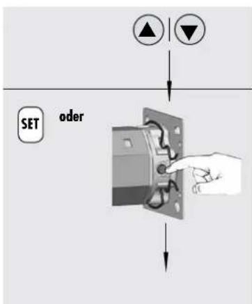

oder

oder
Set the switch/control to „raise (▲) / lower (▼)“ shutter.
Press the relevant set button* and keep it pressed down until the required limit stop position has been reached.
The shutter goes up / down.
* on the motor, the switch setting device or the external button

IMPORTANT
Do not make the shutter move against the mechanical end stops and keep a safety distance of 2-3 cm.
In case of incorrect rotational direction:
Disconnect the power cable from the mains and change the cores for direction of rotation 1 and 2.
Release the set button as soon as the shutter has reached the required position.
The motor stops and the upper/lower limit stop position is saved.
The limit stop position can be adjusted in small increments by briefly pressing the set button.
IMPORTANT
If you encounter any problems while adjusting the limit stops, e.g. such as the tubular motor operating for one rotation only even when pressing the set button, this does not necessarily mean that the motor is defective, but most likely indicates that the adaptor has slid off the motor head.
Check and, if necessary, adjust the adapter (see page 56).
NOTE
Even after a loss of power, the limit stops remain unaffected.

Check your settings and raise and lower the shutter until the limit stops turn off the motor.
Thermal protection
The tubular motors are designed for short-term operation (approx. 4 min)
Operating the motors for longer or frequent switching can cause the motor to heat up and to be switched off by the thermal protection.
If this happens, leave the motor to cool down for 20 minutes.

Emergency shut-down
Function:
After approx. 2,5 sec. the tubular motor stops automatically when the shutter is blocked by an obstacle when being raised (e.g. if the shutter is iced up).
NOTE
Never attempt moving iced-up roller shutters. Remove obstacle and relieve shutter in down direction.

What to do if...?
...the motor doesn't start up?
Possible cause:
There is no mains voltage.
Solution:
Check the supply voltage (230 V) using a voltmeter and check the wiring.
Please pay particular attention to the information on impermissible wiring configurations.
...the direction of rotation is incorrect?
Possible cause:
The control wires are the wrong way round.
Solution:
Disconnect the power cable from the mains and change the cores for direction of rotation 1 and 2.
...the tubular motor comes to a stop when adjusting its settings or during the trial run after running for only a short period of time?
Possible cause:
The adapter (10) may have slid off the limit ring (18) at the motor head (10).
Solution:
Please check whether the adapter (10) is flush with the motor head (12) of the drive and is fully inserted into the winding shaft (5).
Adjust the adapter (10) in such a way that it is flush with the motor head (12) and push the winding shaft (5) onto the adapter (10) (see figure 5). If necessary, re-adjust the limit stops (see page 55).
Changing the limit stops
Raise/ lower the shutter half-way and start from the be-ginning.
...the tubular motor comes to a stop halfway between the two different limit stops when in normal operating mode?
Possible cause 1:
The roller cap (4) may not have been secured to the winding shaft (5) with a screw (see figure 6), which can cause the winding shaft (5) to slide off the motor and thus pull the adapter (10) off the limit ring (18) at the motor head (12).
Solution 1:
Check both the roller cap (4) and adapter (10) position. If necessary, screw the roller cap (4) to the winding shaft (5) using a lock screw and fasten the motor according to the information provided on pages 48-51.
Possible cause 2:
The thermal protection has activated.
Solution 2:
Leave the roller shutter to cool down for 20 minutes.
...the shutter stops during raising?
Possible cause:
Solution:
Iced-up roller shutter or an obstacle in the track.
Remove ice or obstacle.
Relieve the roller shutter in down direction.
| Motor series: | Small Medium | ||||||
| Type: | 6/28 | 10/16 | 10/16 | 20/16 | 30/16 | 40/16 | |
| 6 | 10 | 10 | 20 | 30 | 40 | [Nm] | |
| 28 | 16 | 16 | 16 | 16 | 16 | [rpm] | |
| 230 | 230 | 230 | 230 | 230 | 230 | [V] | |
| 50 | 50 | 50 | 50 | 50 | 50 | [Hz] | |
| 121 | 121 | 112 | 145 | 191 | 198 | [W] | |
| 0.53 | 0.53 | 0.49 | 0.64 | 0.83 | 0.86 | [A] | |
| 4 | 4 | 4 | 4 | 4 | 4 | [Min.] | |
| 5 | 5 | 5 | 5 | 5 | 5 | ||
| 0.75 | 0.75 | 0.75 | 0.75 | 0.75 | 0.75 | [mm²] | |
| 3 | 3 | 3 | 3 | 3 | 3 | [m] | |
| 32 | 32 | 32 | 32 | 32 | 32 | [R] | |
| H | H | H | H | H | H | ||
| I | I | I | I | I | I | ||
| IP 44 | IP 44 | IP 44 | IP 44 | IP 44 | IP 44 | ||
| * | * | * | * | * | * | ||
| 462 | 462 | 465 | 465 | 524 | 524 | [mm] | |
| 35 | 35 | 45 | 45 | 45 | 45 | [mm] | |
| 3 | 3 | 2 | 2 | 2 | 2 | ||

Setting parameters on EIB/KNX shutter actuators for RADEMACHER tubular motors
The following parameters must be adjusted before commissioning to ensure the smooth operation of RADE/MACHER tubular motors with EIB/KNX shutter actuators:
Short-term operation
Where possible, short-term (slat adjustment) operation must be turned off.
E.g. short-term operating mode
Time: = 0 ms
If your software application does not support turning off short-term operation...
...you must ensure that the time between short-term and long-term operation specified for the touch sensor is shorter than the time between short-term and long-term operation specified for the actuator.
This prevents the actuator from suddenly switching off when the sensor button is pressed.
Long-term operation
The motor must be de-energized at the latest after 180 seconds.
E.g. Basis for long-term operation
Basis: = 2.1 s
Factor: = 86
= (2.1s× 86 = 180.6s)

CE Mark and EC Conformity
Tubular motors of series RolloTube Comfort Small and Medium (item numbers: 25400636/25401036/25601096/25602096/25603096/25604096) complies with the requirements of the current European and national directives:

2006/42/EC Machinery directive
2006/95/EC Low voltage directive
2004/108/EC EMC directive
Conformity has been verified. The corresponding declarations and documentation are available on file at the manufacturer's premises.
46414 Rhede (Germany)

RolloTube Comfort Small
RolloTube Comfort Medium
I = Insteldoad (whit)
RADEMACHER Geräte-Elektronik GmbH & Co. KG warrants all new devices for 60 months, that have been installed in accordance with the installation manual. The guarantee covers all design faults, material faults and fabrication faults.
The guarantee does not cover:
Incorrect mounting or installation
Non-observance of the installation and operation manual
Improper operation or utilisation.
External influences such as knocks, blows or weather
Repairs and modifications made by unauthorised third parties
Use of unsuitable accessory parts
Damage due to inadmissible voltage surges (e.g. caused by lightning)
Dysfunction due to superimposed radio frequencies and other radio disturbances.
Any defects occurring within the period of guarantee will be rectified by RADEMACHER at no cost either by repairing or replacing the parts concerned or by delivery of a device of the same value or a new replacement. Generally the original guarantee period will not be extended because of replacement delivery or repair resulting from the guarantee.
NL
46414 Rhede (Germany)
info@rademacher.de
www.rademacher.de
Service:
Hotline 01807 933-171*
Telefax +49 2872 933-253
service@rademacher.de
- 30 Sekunden kostenlos, danach 14 ct/Minute aus dem dt. Festnetz bzw. max. 42 ct/Minute aus dem dt. Mobilfunknetz.
- 30 segundos Gratis, posteriormente 14 pts./minuto desde típos alemanes o max. 42 pts./minuto desde moviles alemanes.
- 30 secondes gratuites, puis 14 ct/minute depuis le réseau fixe allemand ou 42 ct/minute max. depuis le réseau mobile allemand.
- 30 seconds free of charge, subsequently 14 cents / minute from German fixed line networks and max. 42 cents / minute from German cellular networks.
- 30 seconden Gratis, daarna 14 cent/minuit via het Duitse netwerk voor vaste致电orie of max. 42 cent/minuit via het Duitse netwerk voor mobiele致电orie, geldt alleen in Duitsland.