Trumatic C 6002 EH - Boiler TRUMA - Free user manual and instructions
Find the device manual for free Trumatic C 6002 EH TRUMA in PDF.
| Product type | Combined heating and hot water boiler |
| Brand | Truma |
| Model | Trumatic C 6002 EH |
| Weight (without water) | approx. 18.7 kg |
| Hot water volume | 12 liters |
| Gas supply | Liquefied gas (propane/butane), 30 mbar |
| Electrical supply | 12 V (battery) and 230 V (mains) |
| Gas heating output | 2000 W, 4000 W, 6000 W (automatic modulation) |
| Electric heating output | 900 W or 1800 W (selectable) |
| Maximum combined output | 7800 W (gas 6000 W + electric 1800 W) |
| Hot water temperature summer | 40°C or 60°C |
| Hot water temperature winter | up to 80°C |
| Gas consumption | 170 – 480 g/h |
| Maximum air flow rate | 287 m³/h |
| Power consumption 12 V | 0.2 – 5.6 A (heating + hot water) |
| Power consumption 230 V | 900 W (3.9 A) or 1800 W (7.8 A) |
| Maximum water pressure | 2.8 bar |
| Fuses 12 V | F1: 6.3 A, F2: 1.6 A (time-lag) |
| Fuse 230 V | 10 A, time-lag, breaking capacity H |
| Overheating protection | Mechanical switch 230 V (resettable) |
| Safety/drain valve | Electric (12 V), automatic opening in case of frost |
| Routine maintenance | Descaling with vinegar or formic acid, disinfection with Certisil-Argento |
| Warranty | 24 months (material/manufacturing defects) |
| Compliance | CE-0085AS0122, directive 2001/56/EC, EMC, low voltage |
Frequently Asked Questions - Trumatic C 6002 EH TRUMA
User questions about Trumatic C 6002 EH TRUMA
0 question about this device. Answer the ones you know or ask your own.
Ask a new question about this device
Download the instructions for your Boiler in PDF format for free! Find your manual Trumatic C 6002 EH - TRUMA and take your electronic device back in hand. On this page are published all the documents necessary for the use of your device. Trumatic C 6002 EH by TRUMA.
USER MANUAL Trumatic C 6002 EH TRUMA
text_image
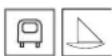
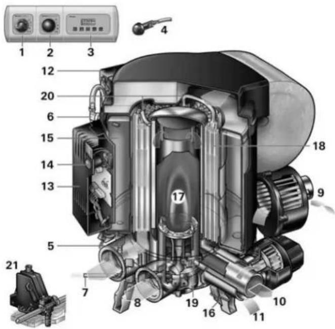
Technical diagram of a mechanical device with numbered components and control panel interface1 Bedienteil
natural_image
Technical line drawing of a mechanical device with a close-up inset showing internal components (no text or symbols)natural_image
Black electronic device labeled 'Cruma Elasi' with circular and rectangular design (no readable text beyond branding)natural_image
Technical illustration of a mechanical component with a flanged housing and a separate view showing internal components (no text or symbols)text_image
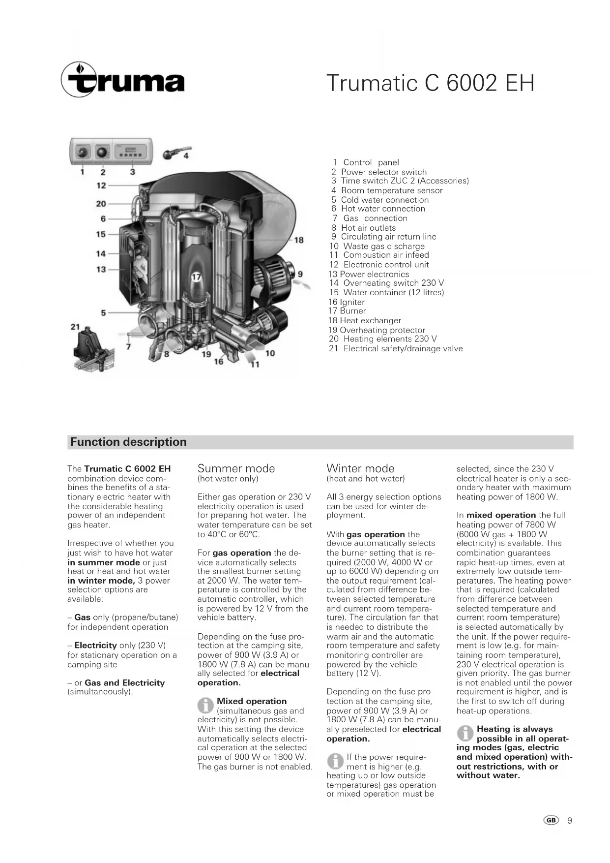
Technical diagram of a mechanical device with numbered components and control panel interface1 Control panel
2 Power selector switch
3 Time switch ZUC 2 (Accessories)
4 Room temperature sensor
5 Cold water connection
6 Hot water connection
7 Gas connection
8 Hot air outlets
9 Circulating air return line
10 Waste gas discharge
11 Combustion air infeed
12 Electronic control unit
13 Power electronics
14 Overheating switch 230 V
15 Water container (12 litres)
16 Igniter
17 Burner
18 Heat exchanger
19 Overheating protector
20 Heating elements 230 V
21 Electrical safety/drainage valve
Function description
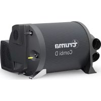
The Trumatic C 6002 EH combination device combines the benefits of a stationary electric heater with the considerable heating power of an independent gas heater.
Irrespective of whether you just wish to have hot water in summer mode or just heat or heat and hot water in winter mode, 3 power selection options are available:
- Gas only (propane/butane) for independent operation
– Electricity only (230 V) for stationary operation on a camping site
- or Gas and Electricity (simultaneously).
Summer mode (hot water only)
Either gas operation or 230 V electricity operation is used for preparing hot water. The water temperature can be set to 40°C or 60°C.
For gas operation the device automatically selects the smallest burner setting at 2000 W. The water temperature is controlled by the automatic controller, which is powered by 12 V from the vehicle battery.
Depending on the fuse protection at the camping site, power of 900 W (3.9 A) or 1800 W (7.8 A) can be manually selected for electrical operation.
Mixed operation (simultaneous gas and electricity) is not possible. With this setting the device automatically selects electrical operation at the selected power of 900 W or 1800 W. The gas burner is not enabled.
Winter mode (heat and hot water)
All 3 energy selection options can be used for winter deployment.
With gas operation the device automatically selects the burner setting that is required (2000 W, 4000 W or up to 6000 W) depending on the output requirement (calculated from difference between selected temperature and current room temperature). The circulation fan that is needed to distribute the warm air and the automatic room temperature and safety monitoring controller are powered by the vehicle battery (12 V).
Depending on the fuse protection at the camping site, power of 900 W (3.9 A) or 1800 W (7.8 A) can be manually preselected for electrical operation.
If the power requirement is higher (e.g. heating up or low outside temperatures) gas operation or mixed operation must be
selected, since the 230 V electrical heater is only a secondary heater with maximum heating power of 1800 W.
In mixed operation the full heating power of 7800 W (6000 W gas + 1800 W electricity) is available. This combination guarantees rapid heat-up times, even at extremely low outside temperatures. The heating power that is required (calculated from difference between selected temperature and current room temperature) is selected automatically by the unit. If the power requirement is low (e.g. for maintaining room temperature), 230 V electrical operation is given priority. The gas burner is not enabled until the power requirement is higher, and is the first to switch off during heat-up operations.
Heating is always possible in all operating modes (gas, electric and mixed operation) without restrictions, with or without water.
Always observe the operating instructions and „Important operating notes“ prior to starting!
The vehicle owner is responsible for the correct operation of the appliance.
Before using for the first time, it is essential to flush the entire water supply through with clean warm water. If the heater is not being used, always drain the water contents if there is a risk of frost! There shall be no guarantee claims for damage caused by frost! Also drain the water prior to repair or maintenance work on the vehicle (in the workshop!) as the electrical safety/ drain valve opens when the appliance is switched dead!
Power selector switch
text_image
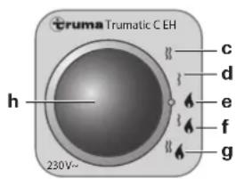
Truma Trumatic C EH h 230V~ c d e f gc = Electric operation
230 V, 1800 W
d = Electric operation
230 V, 900 W
e = Gas operation
f = Mixed operation* (gas and electricity, 900 W)
g = Mixed operation* (gas and electricity, 1800 W)
h = Yellow „electric mode”
indicator lamp
* Winter mode only! In summer mode the unit automatically selects electric operation at the preselected electrical power of 900 W or 1800 W.
Control panel
text_image
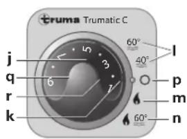
Truma Trumatic C j 5 60° l q 3 40° p r 7 6 m k 60° nj = Rotary switch for room temperature (1 - 9)
k = Green „Operation" monitor lamp
I = Summer mode (water temperature 40°C or 60°C)
m = Winter mode (heating without hot water requirement)
n = Winter mode
(heating with hot water requirement)
p = Rotary „Off“ switch
q = Yellow „Boiler heating phase“ monitor lamp
r = Red „Fault“ monitor lamp
Please observe the vehicle manufacturer's operating instructions when using vehicle-specific switches.
Room thermostat
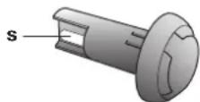
s = Room temperature sensor
To measure the room temperature, an external room temperature sensor (s) is located in the vehicle. The location of the sensor is determined individually by the vehicle manufacturer, depending on the vehicle type; consult the operating instructions for your vehicle for further details.
The thermostat setting on the operating element (1 - 9) must be determined individually depending on the heating requirement and the type of vehicle. For an average room temperature of about 23^ , we recommend a thermostat setting of about 6 - 8.
Taking into operation
Before start-up the following must be checked:
-
Is the cowl free? Remove all covers, and open deck cowl if equipment is being used on boats.
-
Are the gas cylinder and the quick-action stop valve in the gas pipe open?
-
Is the fuse protection for the 230 V power supply at the camping site adequate for the selected output (900 W or 1800 W)?
-
Has the power supply cable for the caravan been fully unwound from the cable reel?
i Heating is always possible in all operating modes (gas, electric and mixed operation) without restrictions, with or without water.
Summer mode (hot water only)
- Select required type of operation at power selector switch (gas or electrical operation).
Mixed operation (gas and electricity) is not possible in summer mode. With this setting the unit automatically selects electric operation at the preselected electrical power of 900 W or 1800 W.
- Set rotary switch to summer mode (I) 40^ C or 60^ C at control unit.
The green „On“ indicator lamp (k) and the yellow water heating indicator lamp (q) on the control unit illuminate when the equipment is switched on. During electrical operation the yellow indicator lamp (h) at the power selector switch also illuminates to indicate 230 V operation.
When the selected water temperature has been reached (40°C or 60°C) the equipment switches off and the yellow control lamp (q) goes off.
Winter mode
Heating with hot water requirement
-
Select required type of operation at power selector switch (gas, electrical or mixed operation).
-
Move rotary knob (j) on the control panel to desired thermostat setting (1 - 9) for room temperature.
-
Move rotary switch on the control panel to „n”.
The green „On“ indicator lamp (k) and the yellow water heating indicator lamp (q) on the control panel illuminate when the equipment is switched on. During electrical operation the yellow indicator lamp (h) at the power selector switch also illuminates to indicate 230 V operation.
Depending on operating mode (gas, electrical or mixed operation) and power requirement (temperature difference between selected and current room temperature) the unit automatically selects the necessary power setting of up to 7800 W.
The unit gradually reduces the power until the selected room temperature is reached. If this temperature has been reached but the water still has to be heated, the circulation fan switches off and the water continues to be heated to a temperature of 60^ C at the lowest power setting.
The water can be heated to up to 80^ C depending on the heating power that is required to achieve the room temperature.
The yellow indicator lamp (q) indicates the hot water heating phase and goes off when the water temperature is reached (60°C).
Heating without hot water requirement
-
Move rotary knob (j) on the control panel to desired thermostat setting (1 - 9) for room temperature.
-
Select required type of operation at power selector switch (gas, electrical or mixed operation).
-
Move rotary switch on the control panel to „m”.
The green „On“ indicator lamp (k) on the control panel illuminate when the equipment is switched on. During electrical operation the yellow indicator lamp (h) at the power selector switch also illuminates to indicate 230 V operation.
In this operating position the yellow indicator lamp (q) only illuminates at water temperatures of less than 10^ C!
Depending on operating mode (gas, electrical or mixed operation) and power requirement (temperature difference between selected and current room temperature) the unit automatically selects the necessary power setting of up to 7800 W.
When the selected room temperature has been reached, the heater switches off (independent of the water temperature).
The water is automatically heated as well if the boiler has been filled. The water temperature can reach up to 80^ C depending on the power and the duration of the heating.
Switching off
Move rotary switch on the control panel to „p“ to switch off.
The fan can continue to run after switching off in order to utilise the residual heat.

In order to prevent unintentional overloading of the power supply when resuming operation, it is advisable to set the unit to gas operation at the power selector switch after switching off.
Always drain water contents if there is a risk of frost!
If the appliance is not to be used for a prolonged period, close the quick-acting valve in the gas supply line and turn off the gas cylinder.
Gas operation fault
If a fault occurs during gas operation the red indicator lamp (r) on the control panel illuminates.
Possible causes can be found in the troubleshooting list.
Unlocking takes place by switching off and then switching on again.
Opening the window switch and closing it again is the equivalent to switching off/on at the control panel (e.g. performing a fault reset)!

If a fault shut-off occurs during mixed operation (e.g. because of empty gas cylinder) the heater continues to run using electricity.
Electrical operation fault
If a fault occurs during electrical operation the yellow indicator lamp (h) on the power selector switch goes off.
Possible causes can be found in the troubleshooting list.

If the 230 V power supply is interrupted for short periods during operation the heating will resume as normal.
Electrical
safety/drain valve
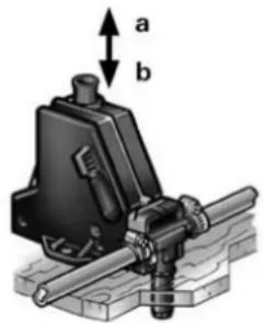
text_image
a ba = Control knob „closed” b = Control knob „drain“

The safety/drain valve is held closed by a elec- coil. To save battery er, we recommend to the valve if the vehicle in use for a prolonged bed!
If the temperature at the safety/drain valve is less than 4^ C, the water contents may discharge on its own accord if the appliance is not in operation (also if there is a failure)! To avoid water loss, switch the device on (Summer or Winter mode) and close the safety/drain valve at the control knob by raising it up (position a).
Without heater operation, the safety/drain valve can only be closed again at temperatures above 8°C!
The draining socket of the electrical safety/drain valve must always be kept clear (free from slush, ice, leaves etc.)! There shall be no guarantee claims for damage caused by frost!
Filling the water heater
- Close electrical safety/drain valve at the control knob by lifting up (position a).
At temperatures of around 8^ C and less, switch on the heater or water heater first, to make sure the valve does not open again!
-
Switch on power for water pump (main switch or pump switch).
-
Open hot water taps in kitchen and bathroom, (set preselecting mixing taps or single-lever fittings to "hot"). Leave taps open until the water heater has forced out air and filled up with water and water is flowing out of the taps.

If just the cold water system is being operated, without using the water heater, the heater tank also fills up with water. In order to avoid damage by frost, the water contents must be drained by operating the safety/drain valve, also when the water heater has not been used. As an alternative, two shutoff valves, resistant to hot water, can be fitted in front of the cold and hot water connection.

When connecting to a central water supply (rural or city mains), a pressure reduction valve must always be installed to prevent pressures above 2.8 bar from developing in the water heater.
Draining the
water heater
-
Interrupt power for water pump (main switch or pump switch).
-
Open hot water taps in kitchen and bathroom.
-
Open electrical safety/drain valve at control knob by pressing in (position b).
The water heater content is now emptied to the outside through the safety/drain valve. Place a bucket beneath the outlet to check whether the water content has completely drained away (12 litres!). There shall be no guarantee claims for damage caused by frost!
Maintenance Important operating notes
The water container used is made of stainless steel, which is foodstuff-compatible.
Use wine vinegar for descaling the water heater, this being introduced into the appliance via the water supply. Allow the product to react and then thoroughly flush out the appliance with plenty of fresh water. To sterilise the water we recommend „Certisil-Argento“. Other products, particularly those containing chlorine are unsuitable.
To avoid infestation by micro-organisms, the boiler must be heated to 70^ C at regular intervals (only possible in winter operation).
Do not use the water as drinking water!
Fuses 12 V
The 12 V fuses for the device are located on the electronic control unit (12).
The fine-wire fuse must only be replaced by a fuse of the same design.
F1: 6.3 A, slow-acting
F2: 1.6 A, slow-acting
Fuse 230 V
The fuses and power connection cables must always be replaced by experts!
Disconnect all poles of the unit from the mains before opening the housing containing the power electronics.
The 230 V fuse of the unit is in the power electronics (13) on the unit.
This fine fuse must always be replaced with a fuse of the same type: 10 A, slow, interrupting capacity „H“.
Overheating protection 230 V
The 230 V heating facility has a mechanical overheating switch. If the 12 V power supply is interrupted during operation or during the after-run period, for example, the temperatures within the unit could trigger the overheating protection.
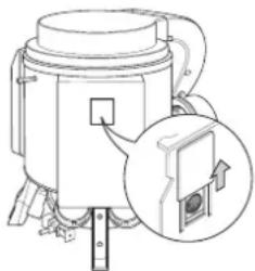
natural_image
Technical illustration of a mechanical device with a close-up inset showing a component detail (no text or symbols)To reset the overheating protection, let the heater cool down, slide cover on power electronics (13) upwards and push in the red button.
Always use original Truma spare parts for maintenance and repair work.
-
If the cowl has been placed near or directly beneath an opening window, the device must be equipped with an automatic shut-off device in order to prevent operation with the window open.
-
The integrity and tight fit of the exhaust gas double duct must be checked regularly, particularly at the end of long trips. Also check the mounting of the appliance and the cowl.
-
Following a blow-back (misfire) always have the exhaust gas system checked by an expert!
-
Always keep the cowl for the exhaust duct and combustion air intake free of contamination (slush, ice, leaves etc.).
-
The liquid gas burner operates fan-supported, which ensures trouble-free function even when on the move. National restrictions must be observed with regard to operation when on the move.
-
The installed temperature limiter shuts off the gas supply if the appliance becomes too hot. Therefore do not shut the warm air outlets and the opening for the returning circulating air.
-
The installer or vehicle owner must apply the yellow sticker with the warning information, which is enclosed with the appliance, to a place in the vehicle where it is clearly visible to all users (e.g. on the wardrobe door)! Ask Truma to send you stickers, if necessary.
-
Directive 2004/78/EC stipulates that a safety shut-off device is required if motor homes are being heated while driving. The safety shut-off device is also recommended for safety reasons if caravans are being heated while driving.
The Truma SecuMotion gas pressure regulator meets this requirement.
If no Truma SecuMotion gas pressure regulator is installed, the gas cylinder must be closed whilst driving and information signs must be attached to the cylinder cabinet and in the vicinity of the control panel.
Accessories General safety notes
If the gas system is leaking or if there is a smell of gas:
– extinguish all naked flames
- do not smoke
- switch off the appliances
- shut off the gas cylinder
– open windows and door
- do not actuate any
electrical switches
– have the entire system checked by an expert!
Repairs may only be carried out by an expert!
A new O-ring must always be installed after dismantling the exhaust duct!
-
Any modifications to the unit (including the exhaust duct and the cowl) or the use of spare parts and accessories that are important to the operation of the system (e.g. the time switch) that are not original Truma parts and failure to follow the installation and operating instructions will cancel the warranty and indemnify Truma from any liability claims. It also becomes illegal to use the appliance, and in some countries this even makes it illegal to use the vehicle.
-
The operating pressure of the gas supply must correspond with the operating pressure of the device (30 mbar).
-
Liquid gas systems must comply with the technical and administrative regulations of the respective country of use (e.g. EN 1949 for vehicles or EN ISO 10239 for boats in Europe). National directives and regulations (e.g. DVGW worksheet G 607 for vehicles and G 608 for boats in Germany) must be complied with.
The testing of the gas system must be repeated every two years by a qualified specialist and, if appropriate, confirmed on the inspection certificate (in Germany, for example, DVGW Worksheet G 607 for motor vehicles or G 608 for boats).
The vehicle owner is always responsible for arranging the inspection.
-
Liquid gas equipment must not be used when refuelling, in multi-storey car parks, in garages or on ferries.
-
During the initial operation of a brand new appliance (or after it has not been used for some time), a slight amount of fumes and smell may be noticed for a short while. It is a good idea to heat the device up several times in mixed/summer operation (60°C) and to make sure that the area is well ventilated.
-
If the burner makes an unusual noise or if the flame lifts off, it is likely that the regulator is faulty and it is essential to have it checked.
-
Items sensitive to heat (e.g. spray cans) must not be stored in the installation area, since excess temperatures may under certain circumstances be incurred there.
-
Only pressure regulators that comply with EN 12864 (in vehicles) and EN ISO 10239 (for boats) with a fixed delivery pressure of 30 mbar must be used for the gas system. The flow rate of the pressure regulator must correspond to at least the maximum consumption of all devices installed by the system manufacturer.
For vehicles we recommend the Truma SecuMotion gas pressure regulator and the Truma DuoComfort automatic changeover valve for the two-cylinder system.
At temperatures of around 0^ C or less the gas pressure regulator and the changeover valve must be operated using the EisEx de-icing system.
Controller connecting hoses that meet national regulations must always be used in the respective country for which the equipment is destined. These hoses must be checked regularly for brittleness. Winter-proof special hoses must always be used if the equipment is operated during the winter.
Pressure regulating equipment and hoses must be replaced with new ones no more than 10 years after the date of manufacture (every 8 years if used commercially). This is the responsibility of the operator.
Truma Timer ZUC 2 complete with 3 m connecting cable (part no. 34042-01).
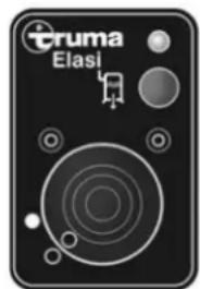
natural_image
Black electronic device labeled 'Eruma Elasi' with circular and rectangular buttons (no readable text beyond branding)Remote control for electrical safety/drain valve, complete with 3 m connecting cable (part no. 34170-01).
The electrical accessories are fitted with a plug and can be connected individually.
Extension cables for the control panel, the ZUC 2 timer and remote control panel for the drain valve are available if required.
text_image
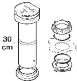
30 cmCowl extension KVC for winter camping (part no. 34070-01). The cowl extension must be removed whilst driving.
Double-skin leadthrough for caravan-double-skin roofs (part no. 34080-01).
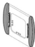
As standard, Truma supplies a suitable cover frame, in agate grey colour, for every control panel/every time switch.
Shrouding frames are available in different colours as a special accessory, and side sections for finishing off the shrouding frames are also available in 8 different colours.
Please contact your dealer.
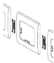
Clip rows (part no. 34000-65900). For installing several Truma control panels next to one another.
natural_image
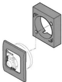
Technical illustration of a mechanical component with two views, one showing internal components and the other a circular assembly (no text or symbols)Surface-mounting frame for Truma control panel (part no. 40000-52600). Combination with the side pieces is not possible.
Technical data
terminated in accordance with EN 624 or Truma test conditions
Type of gas:
Liquid gas (propane/butane)
Operating pressure:
30 mbar
Water contents:
12 litres
Heating up time from approx. 15°C to approx. 60°C:
Summer-/gas operation: approx. 30 minutes
(measured according to EN 15033)
Summer-/electrical operation (1800 W): approx. 45 min.
Winter mode: approx. 60 min. upward
(depending on the heat output)
Water pressure:
max. 2.8 bar
Rated thermal output:
Liquid gas: 2000 W, 4000 W, 6000 W
Electrical: 900 W, 1800 W
Gas consumption:
170 - 480 g/h
Air delivery volume:
max. 287 m³/h (free-blowing without warm-air duct)
Current input at 12 V:
Heater + water heater: 0.2 - 5.6 A
Heating up of water heater: 0.4 A
Stand-by: 0.001 A
Current input of electrical safety/drain valve at 12 V:
0.035 A
Current input of 230 V:
900 W (3.9 A) or 1800 W (7.8 A)
Weight:
approx. 18.7 kg (without water contents)
Declaration of conformity :
The Trumatic C 6002 EH has been tested by the DVGW and complies with the gas equipment directive (90/396/EEC) and the other applicable EC directives. The following CE Product Ident. No. is available for EU countries:
CE-0085AS0122.
The heater complies with heater directive 2001/56/EC and supplements 2004/78/EC and 2006/119/EC and bears the type approval number: e1 00 0146.
The heater complies with vehicle engine interference suppression directive 72/245/EEC with supplements 2004/104/EC and 2005/83/EC, and bears type approval number: e1 03 2499.
The heater complies with EMC directive 89/336/EEC and low voltage directive 73/23/EEC.

The right to effect technical modifications is reserved!
Manufacturer's terms of warranty
1. Case of warranty
The manufacturer grants a warranty for malfunctions in the appliance which are based on material or production faults. In addition to this, the statutory warranty claims against the seller remain valid.
A claim under warranty shall not pertain:
– for parts subject to wear and in cases of natural wear and tear,
- as a result of using components in the units that are not original Truma parts and using unsuitable gas pressure regulators,
- as a consequence of failure to respect Truma instructions for installation and use,
– as a consequence of improper handling,
- as a consequence of improper transport packing, not arranged by Truma.
2. Scope of warranty
The warranty is valid for malfunctions as stated under item 1, which occur within 24 months after conclusion of the purchase agreement between the seller and the final consumer. The manufacturers will make good such defects by subsequent fulfilment, i.e. at their discretion either by repair or replacement. In the event of manufacturers providing service under warranty, the term of the warranty shall not recommence anew with regard to the repaired or replaced parts; rather, the old warranty period shall continue to run. More extensive claims, in particular claims for compensatory damages by purchasers or third parties, shall be excluded. This does not affect the rules of the product liability law.
The manufacturer shall bear the cost of employing the Truma customer service for the removal of a malfunction under warranty – in particular transportation costs, travelling expenses, job and material costs, as long as the service is carried out in Germany. The warranty does not cover customer service work in other countries.
Additional costs based on complicated removal and installation conditions of the appliance (e.g. removal of furniture or parts of the vehicle body) do not come under warranty.
3. Raising the case of warranty
The manufacturer's address is:
Truma Gerätetechnik GmbH & Co. KG, Wernher-von-Braun Straße 12, 85640 Putzbrunn. In Germany, always notify the Truma service centre if problems are encountered; in other countries the relevant service partners should be contacted (see list of addresses). Any complaints are to be described in detail. In addition, the properly completed guarantee certificate is to be presented, or the factory number of the unit and the date of purchase given.
In order for the manufacturers to be able to determine whether an incident subject to guarantee has occurred, the end user must, at his own risk, bring the device to the manufacturers or send it to them. If there is damage to heaters (heat exchangers), the gas pressure regulator must also be sent back to the factory.
In instances of the device being sent to the works, dispatch is to be effected by freight transport. In cases under guarantee, the works shall bear the transport costs or the costs of delivery and return. If the damage is deemed not to be a warranty case, the manufacturer shall notify the customer and shall specify repair costs which shall not be borne by the manufacturer; in this case, the customer shall also bear the shipping costs.
Fault Cause Rectification
Gas operation
| No control lamp lights up when the system is switched on (winter and summer mode). | - No supply voltage. | - Check battery voltage (12 V). |
| - Check all electrical plug connections. | ||
| - Device fuse or vehicle fuse defective. | - Check device fuse (see Maintenance). | |
| - Check vehicle fuse. | ||
| The green indicator lamp comes on when the equipment is switched on, but the heater is not operating. | - The temperature setting on the control panel is lower than the room temperature. | - Select higher room temperature at the control panel. |
| - Open window above cowl (window switch). | - Close window. | |
| The red monitor lamp flashes after the heating system has been switched on. | - Battery voltage is too low < 10.5 V. | - Charge battery. |
| About 30 seconds after the heating has been switched on, the red monitor lamp lights up and remains steady. | - Gas cylinder or quick-closure valve in the gas line is closed. | - Check gas feed. |
| - Air feed interrupted. | - Check cowl for possible coverage. | |
| - If being used on boats, open the deck cowl. | ||
| Heating switches to fault mode after an extended period of operation. | - Hot-air outlets blocked. | - Check individual outlet apertures. |
| - Gas pressure regulator iced up. | - Use de-icing system controller (EisEx). | |
| - Butane content in the gas cylinder too high. | - Use propane (at temperatures below 10°C in particular, butane is unsuitable for heating purposes). |
Electrical operation 230 V
| The green indicator lamp on the control panel illuminates when the unit is switched on, the yellow indicator lamp on the power selector switch does not illuminate and the heating does not become warm. | - No supply voltage. | - Check 230 V supply voltage and fuses. |
| - Device fuse defective. | - Check device fuse (see Maintenance). | |
| - Overheating switch has triggered. | - Reset overheating switch (see Maintenance). |
Water supply
| When the heating system is switched off, the electrical safety/drain valve opens. | Outside temperature below 4°C. | Switch the heating on (at temperatures of about 4°C and below the drain valve will open automatically). |
| The valve remains open even after the heating has been switched on. | No 12 V power supply at the drain valve. | Check 12 V supply voltage and fuses. |
| The electrical safety/drain valve will no longer close. | Outside temperature below 8°C. | Switch the heating on (without heating operation, the drain valve will not close again until temperatures above 8°C have been reached). |
| The valve remains open even after the heating has been switched on. | No 12 V power supply at the drain valve. | Check 12 V supply voltage and fuses. |
| Water dripping from the electrical safety/drain valve. | Water pressure too high. | Check pump pressure (max. 2.8 bar).If connected to a central water supply (rural or urban connection), a pressure reducer must be used, which will prevent pressures higher than 2.8 bar entering the boiler. |
text_image
Technical diagram of a mechanical device with numbered components and labeled parts, including control panel and mechanical parts.natural_image
Technical line drawing of a mechanical device with an inset showing a close-up view of a component (no text or symbols present)natural_image
Black electronic device labeled 'Etruma Elasi' with circular and rectangular buttons (no readable text beyond branding)natural_image
Technical illustration of a mechanical assembly with two components, one showing a flanged housing and the other a coiled spring (no text or symbols)text_image
Technical diagram of a mechanical device with numbered components and control panel interfacenatural_image
Technical line drawing of a mechanical device with an inset showing a close-up view of a component (no text or symbols present)natural_image
Black electronic device labeled 'Etruma Elasi' with circular and rectangular buttons (no readable text beyond branding)natural_image
Technical illustration of a mechanical assembly with two components, one showing a circular housing and the other a flanged base (no text or symbols)text_image
Technical diagram of a mechanical device with numbered components and control panel interfacenatural_image
Technical line drawing of a mechanical device with an inset showing a close-up view of a component (no text or symbols present)natural_image
Front panel of a Truma Elasi device with circular sensor and control buttons (no readable text or symbols)natural_image
Technical illustration of a mechanical assembly with two components, one showing a flange and the other a rotating component (no text or symbols)text_image
Technical diagram of a mechanical device with numbered components and control panel interfacenatural_image
Technical line drawing of a mechanical device with an inset showing a close-up view of a component (no text or symbols present)natural_image
Black electronic device labeled 'Etruma Elasi' with circular and rectangular design (no readable text beyond branding)natural_image
Technical illustration of a mechanical component with two views, one showing internal features and the other showing a circular feature (no text or symbols present)text_image
Technical diagram of a mechanical device with numbered components and labeled parts, including control panel and mechanical parts.natural_image
Technical line drawing of a mechanical device with an inset showing a close-up view of a component (no text or symbols present)natural_image
Black electronic device labeled 'Eruma Elasi' with circular design and control buttons (no readable text beyond branding)natural_image
Technical illustration of a mechanical component with two views, one showing internal circular features and the other a rectangular housing (no text or symbols)natural_image
Exterior view of a modern glass building with 'truma' signage, surrounded by trees and water features (no readable text beyond logo)Quality with tradition
Truma was founded in 1949. This middle-sized family concern is today Europe's leading manufacturer of gas heating systems for motor vehicles.
Truma develops, manufactures, and markets comfort equipment for caravans, motor homes, and boats:
• Liquid gas heating systems
- Hot-air systems
• Air-conditioning systems
• Hot-water production systems
- Gas lights
- Convenience accessories for gas systems
• Manoeuvring aid for caravans
and supplementary heating systems for commercial vehicles.
The Truma Group also includes the company of ALDE, a Swedish manufacturer of hot water heating systems, and MPV-TRUMA, a firm which supplies technical medical products.
natural_image
Abstract logo design with a stylized flame and checkmark inside a circle (no text or symbols)To be filled in by the dealer. Udfyldes af forhandleren.
A remplir par le commerçant. A ser rellendada por el commerciente.
Applicable for Germany only!