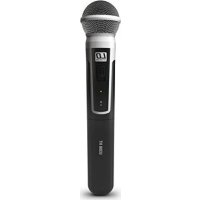
U308 MD - Microphone LD Systems - Free user manual and instructions
Find the device manual for free U308 MD LD Systems in PDF.


| Product Type | Wireless Microphone (Handheld Transmitter) |
| Brand | LD Systems |
| Model | U308 MD |
| Category | Microphone |
| Microphone Type | Dynamic |
| Polar Pattern | Cardioid |
| Frequency Response | 55 - 16,000 Hz |
| Frequency Band | 823 - 832 MHz and 863 - 865 MHz |
| Channels | 12 |
| RF Output Power | 10 mW PEP |
| Antenna Gain | 0.5 dBi |
| Power Supply | 2 AA batteries (alkaline recommended) |
| Battery Life | Up to 10 hours (depending on batteries) |
| Dimensions (L x Ø) | 257 x 50 mm |
| Weight (without batteries) | 0.235 kg |
| Connectors | Integrated antenna, infrared interface |
| Main Functions | Infrared synchronization (ASC), pilot tone, interchangeable microphone head, On/Off switch, status LED |
| Included Accessories | 2 AA batteries |
| Maintenance and Cleaning | Use a dry cloth; remove batteries if not used for an extended period |
| Safety | Do not open the device; use only leak-proof alkaline batteries; respect polarity |
| Operating Temperature | 5 °C to 40 °C |
| Compatibility | U300 series receivers (same frequency band) |
Frequently Asked Questions - U308 MD LD Systems
Examples: LDU500CH (hypercardioid condenser), LDU500DC (cardioid dynamic).
User questions about U308 MD LD Systems
0 question about this device. Answer the ones you know or ask your own.
Ask a new question about this device
Download the instructions for your Microphone in PDF format for free! Find your manual U308 MD - LD Systems and take your electronic device back in hand. On this page are published all the documents necessary for the use of your device. U308 MD by LD Systems.
USER MANUAL U308 MD LD Systems
natural_image
Exterior view of a modern audio recording device with multiple speakers and antennas (no visible text or symbols)U300® SERIES
DIVERSITY WIRELESS SYSTEMS
CONTENTS / INHALTSVERZEICHNIS / CONTENU / CONTENIDO / TREŚĆ / CONTENUTO
ENGLISH
PREVENTIVE MEASURES 3
INTRODUCTION
CONNECTIONS, OPERATING AND DISPLAY ELEMENTS 6
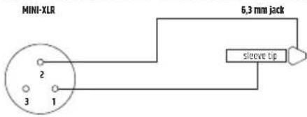
PIN ALLOCATION FOR MINI XLR CONNECTOR
(POCKET TRANSMITTER) 10
TROUBLESHOOTING
OPTIONAL ACCESSORIES 11
TECHNICAL DATA 13
MANUFACTURER'S DECLARATIONS 17
DEUTSCH
SICHERHEITSHINWEISE
EINFÜHRUNG
We have designed this product to operate reliably over many years. LD Systems stands for this with its name and many years of experience as a manufacturer of high-quality audio products. Please read this User's Manual carefully, so that you can begin making optimum use of your LD Systems product quickly. You can find more information about LD-SYSTEMS at our Internet site WWW.LD-SYSTEMS.COM
PREVENTIVE MEASURES
- Please read these instructions carefully.
- Keep all information and instructions in a safe place.
- Follow the instructions.
- Observe all safety warnings. Never remove safety warnings or other information from the equipment.
- Use the equipment only in the intended manner and for the intended purpose.
- Use only sufficiently stable and compatible stands and/or mounts (for fixed installations). Make certain that wall mounts are properly installed and secured. Make certain that the equipment is installed securely and cannot fall down.
- During installation, observ e the applicable safety regulations for your country.
- Never install and operate the equipment near radiators, heat registers, ovens or other sources of heat. Make certain that the equipment is always installed so that is cooled sufficiently and cannot overheat.
- Never place sources of ignition, e.g., burning candles, on the equipment.
- Ventilation slits must not be blocked.
- Keep a minimum distance of 20 cm around and above the device.
- Do not use this equipment in the immediate vicinity of water (does not apply to special outdoor equipment - in this case, observe the special instructions noted below. Do not expose this equipment to flammable materials, fluids or gases. Avoid direct sunlight!
- Make certain that dripping or splashed water cannot enter the equipment. Do not place containers filled with liquids, such as vases or drinking vessels, on the equipment.
- Make certain that objects cannot fall into the device.
- Use this equipment only with the accessories recommended and intended by the manufacturer.
- Do not open or modify this equipment.
- After connecting the equipment, check all cables in order to prevent damage or accidents, e.g., due to tripping hazards.
- During transport, make certain that the equipment cannot fall down and possibly cause property damage and personal injuries.
- If your equipment is no longer functioning properly, if fluids or objects have gotten inside the equipment or if it has been damaged in anot her way, switch it off immediately and unplug it from the mains outlet (if it is a powered device). This equipment may only be repaired by authorized, qualified personnel.
- Clean the equipment using a dry cloth.
- Comply with all applicable disposal laws in your country. During disposal of packaging, please separate plastic and paper/cardboard.
- Plastic bags must be kept out of reach of children.
- Please note that changes or modifications not expressly approved by the party responsible for compliance could void the user's authority to operate the equipment.
FOR EQUIPMENT THAT CONNECTS TO THE POWER MAINS
- CAUTION: If the power cord of the device is equipped with an earthing contact, then it must be connected to an outlet with a protective ground. Never deactivate the protective ground of a power cord.
- If the equipment has been exposed to strong fluctuations in temperature (for example, after transport), do not switch it on immediately. Moisture and condensation could damage the equipment. Do not switch on the equipment until it has reached room temperature.
- Before connecting the equipment to the power outlet, first verify that the mains voltage and frequency match the values specified on the equipment. If the equipment has a voltage selection switch, connect the equipment to the power outlet only if the equipment values and the mains power values match. If the included power cord or power adapter does not fit in your wall outlet, contact your electrician.
- Do not step on the power cord. Make certain that the power cable does not become kinked, especially at the mains outlet and/or power adapter and the equipment connector.
- When connecting the equipment, make certain that the power cord or power adapter is always freely accessible. Always disconnect the equipment from the power supply if the equipment is not in use or if you want to clean the equipment. Always unplug the power cord and power adapter from the power outlet at the plug or adapter and not by pulling on the cord. Never touch the power cord and power adapter with wet hands.
- Whenever possible, avoid switching the equipment on and off in quick succession because otherwise this can shorten the useful life of the equipment.
- IMPORTANT INFORMATION: Replace fuses only with fuses of the same type and rating. If a fuse blows repeatedly, please contact an authorised service centre.
- To disconnect the equipment from the power mains completely, unplug the power cord or power adapter from the power outlet.
- If your device is equipped with a Volex power connector, the mating Volex equipment connector must be unlocked before it can be removed. However, this also means that the equipment can slide and fall down if the power cable is pulled, which can lead to personal injuries and/or other damage. For this reason, always be careful when laying cables.
- Unplug the power cord and power adapter from the power outlet if there is a risk of a lightning strike or before extended periods of disuse.

CAUTION:
To reduce the risk of electric shock, do not remove cover (or back). There are no user serviceable parts inside. Maintenance and repairs should be exclusively carried out by qualified service personnel.
The warning triangle with lightning symbol indicates dangerous uninsulated voltage inside the unit, which may cause an electrical shock.

The warning triangle with exclamation mark indicates important operating and maintenance instructions.

Warning! This symbol indicates a hot surface. Certain parts of the housing can become hot during operation. After use, wait for a cool-down period of at least 10 minutes before handling or transporting the device.

Warning! This device is designed for use below 2000 metres in altitude.

Warning! This product is not intended for use in tropical climates.
CAUTION! HIGH VOLUMES IN AUDIO PRODUCTS!
This device is meant for professional use. Therefore, commercial use of this equipment is subject to the respectively applicable national accident prevention rules and regulations. As a manufacturer, Adam Hall is obligated to notify you formally about the existence of potential health risks. Hearing damage due to high volume and prolonged exposure: When in use, this product is capable of producing high sound-pressure levels (SPL) that can lead to irreversible hearing damage in performers, employees, and audience members. For this reason, avoid prolonged exposure to volumes in excess of 90 dB.
NOTE: This equipment has been tested and found to comply with the limits for a Class B digital device, pursuant to Part 15 of the FCC Rules. These limits are designed to provide reasonable protection against harmful interference in a residential installation. This equipment generates, uses and can radiate radio frequency energy and, if not installed and used in accordance with the instructions, may cause harmful interference to radio communications. However, there is no guarantee that interference will not occur in a particular installation. If this equipment does cause harmful interference to radio or television reception, which can be determined by turning the equipment off and on, the user is encouraged to try to correct the interference by one or more of the following measures:
- Reorient or relocate the receiving antenna.
- Increase the separation between the equipment and receiver.
- Connect the equipment into an outlet on a circuit different from that to which the receiver is connected.
- Consult the dealer or an experienced radio/TV technician for help.
INTRODUCTION
Developed in Germany, the UHF Diversity wireless systems from the U300 ^® series deliver excellent audio performance. They achieve a range of 100 meters in ideal conditions and are available in 5 frequency bands. Up to six U300 ^® systems can be used simultaneously for each frequency band. Convenient one-touch synchronisation of transmitter and receiver via infrared facilitates fast, trouble-free wireless connection and the squelch function with pilot tone ensures fail-safe operation.
• Available with hand or pocket transmitter
- ASC infrared frequency synchronisation
- Fail-safe operation provided by pilot tone
- 12 channels
- Up to 6 systems can be used simultaneously (up to 3 twin receivers)
• Belt-pack transmitter with gain control and status LED
• Dynamic hand-held microphone with status LED
- U500® microphone heads also suitable for U300® hand-held transmitter
- Long battery life
• Available in the following frequencies:
470 - 490 MHz (LDU3047)
514 - 542 MHz (LDU3051)
584 - 608 MHz (LDU305)
655 - 679 MHz (LDU306)
823 - 832 MHz and 863-865 MHz (LDU308)
Please note: The use of the wireless microphone system may require a license, depending on the country of use. For detailed information please contact the relevant authority in your country.
Pilot tone
The pilot tone function protects a wireless microphone system against interference, for example, unwanted signals from other radio transmission systems. The transmitter adds a second, inaudible signal (the pilot tone) to the actual signal which is to be transmitted. The receiver identifies it as the matching pilot tone and frees the associated signal. Signals without a matching pilot tone remain muted.
Included
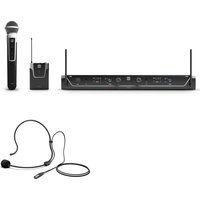
LDU30xHHD: Receiver plus hand-held transmitter with dynamic capsule (cardioid), power supply, 2 x AA batteries, audio cable, manual
LDU30xBPH: Receiver plus pocket transmitter and headset (black), power supply, 2 x AA batteries, audio cable, manual
LDU30xBPG: Receiver plus pocket transmitter and guitar cable, power supply, 2 x AA batteries, audio cable, manual
LDU30xBPL: Receiver plus pocket transmitter and Lavalier microphone, power supply, 2 x AA batteries, audio cable, manual
LDU30xBPW: Receiver plus pocket transmitter and clip-on microphone for wind instruments, power supply, 2 x AA batteries, audio cable, manual
LDU30xHHD2: Twin receiver plus 2 x hand-held transmitters with dynamic capsules (cardioid), power supply, 4 x AA batteries, 2 x audio cables, rack kit, manual
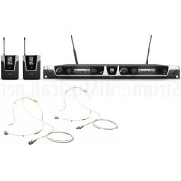
LDU30xBPH2: Twin receiver plus 2 x pocket transmitters and 2 x headsets (black), power supply, 4 x AA batteries, 2 x audio cables, rack kit, manual
CONNECTIONS, OPERATING AND DISPLAY ELEMENTS
RECEIVER

POWER
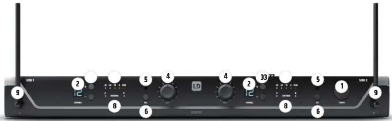
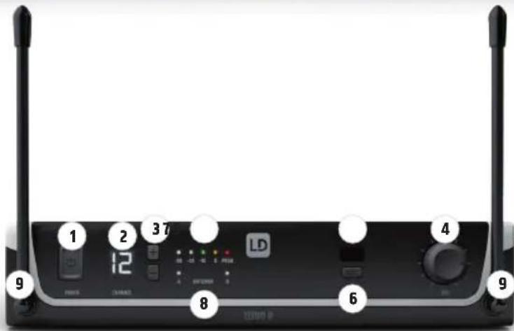
On/off switch. Press and hold the button for approximately 1 seconds to turn the device on or off.

CHANNEL DISPLAY
Illuminated LC display to show the radio channel.

CHANNEL + / -
Push buttons to select the radio channel 01 to 12. To establish a wireless connection between the transmitter and the receiver, the radio frequency on both receivers must match (synchronisation process as described under point 6. ASC).
Note: Both receivers cannot be set to the same radio channel on the twin receiver.

VOL
Rotary knob to adjust the output volume.

IR INTERFACE
Infrared interface for synchronising the receiver's radio channel with the transmitter.

ASC
To synchronise the transmitter with the radio channel set in the receiver, position the infra-red port of the transmitter directly in line with the infra-red interface of the receiver and switch on the transmitter and receiver (distance about 10 cm, IR interface of the hand transmitter is below the status LED, IR interface of the pocket transmitter on the front side). Now press the ASC button to start the synchronisation process. A red LED indicator will light up in the window of the IR interface during the process. After a few seconds, the process is completed and one of the LED indicators ANTENNA A and B will light up (= wireless connection exists).

LEVEL INDICATOR
5-segment LED chain to display the audio signal level.
8 ANTENNA A - B
Indicator LEDs for the antenna systems A and B. The antenna system with the stronger radio signal is activated and the corresponding indicator LED lights up.
9 RECEPTION ANTENNAS A - B
For optimum reception, please position the antennas in an upward-facing V-position.
10 DC SOCKET
Low-voltage socket for the power supply to the device. Please use only the supplied mains adapter.
11 CABLE STRAIN-RELIEF
Cable strain relief for power adapter cable.
12 UNBALANCED OUTPUT
Unbalanced audio output via 6.3mm jack socket.
⑬ INSTRUMENT/LINE (UNBALANCED OUTPUT)
Switch for level and impedance-matching to instruments or line inputs of an amplifier or mixer. Using a suitable tool (e.g. a ballpoint pen), push the switch into the depressed INSTRUMENT position for connection to the input of an instrument amplifier (guitar or bass amp) and for connection to the line-input of a mixer or amplifier, select the non-depressed position LINE.
14 BALANCED OUTPUT
Balanced audio output via 3-pin XLR jack.
Unbalanced audio output via 6.3mm jack socket (twin receiver only, mix of signals from channels 1 and 2).
16 INSTRUMENT/LINE MIX OUT (UNBALANCED OUTPUT)
Switch for adjusting the level and impedance of the jack output to the instrument or line inputs of an amplifier or mixer. Using a suitable tool (e.g. a ballpoint pen), push the switch into the depressed INSTRUMENT position for connecting the receiver to the input of an instrument amplifier (guitar or bass amp). To connect to the line-input of a mixer or amplifier, select the non-depressed position LINE.
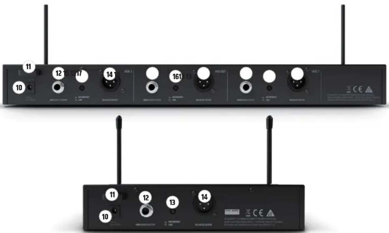
Balanced audio output via 3-pole XLR socket (twin receiver only, mix of signals from channels 1 and 2).
HAND-HELD TRANSMITTER
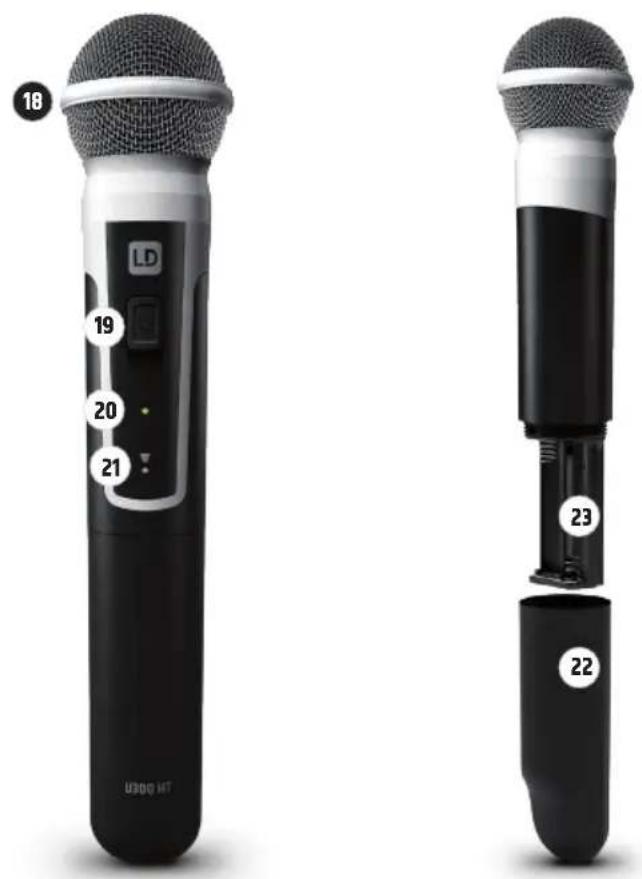
18 MICROPHONE HEAD
The microphone head is interchangeable, the hand-held transmitter is compatible with the microphone heads from the LD U500 ^® series, available separately.
19 ON / OFF
On/off switch. Move the switch to the ON position to turn on the hand-held transmitter, and to the OFF position to turn it off.
20 STATUS LED
If the charge status of the batteries is sufficient, the LED lights up green when the hand transmitter is switched on. If the LED lights up red, the charge status is weak. In this case, replace the batteries (2 x AA/LR6 type, alkaline). During the synchronisation process, the LED flashes green and amber.
21 IR INTERFACE
Infra-red interface for synchronising the radio channel from receiver and transmitter.
22 BATTERY COMPARTMENT COVER
To replace the batteries, open the hand transmitter battery compartment by rotating it anti-clockwise and pulling it from the housing. Remove the used batteries and replace with new batteries (AA), following the diagram in the battery compartment. Replace the battery compartment cover and rotate it clockwise to close the battery compartment. If the transmitter is not used for a long period, remove the batteries to avoid damage to the transmitter from leaking batteries.
23 BATTERY COMPARTMENT
Battery compartment for two AA batteries. Please use only leak-proof brand products.
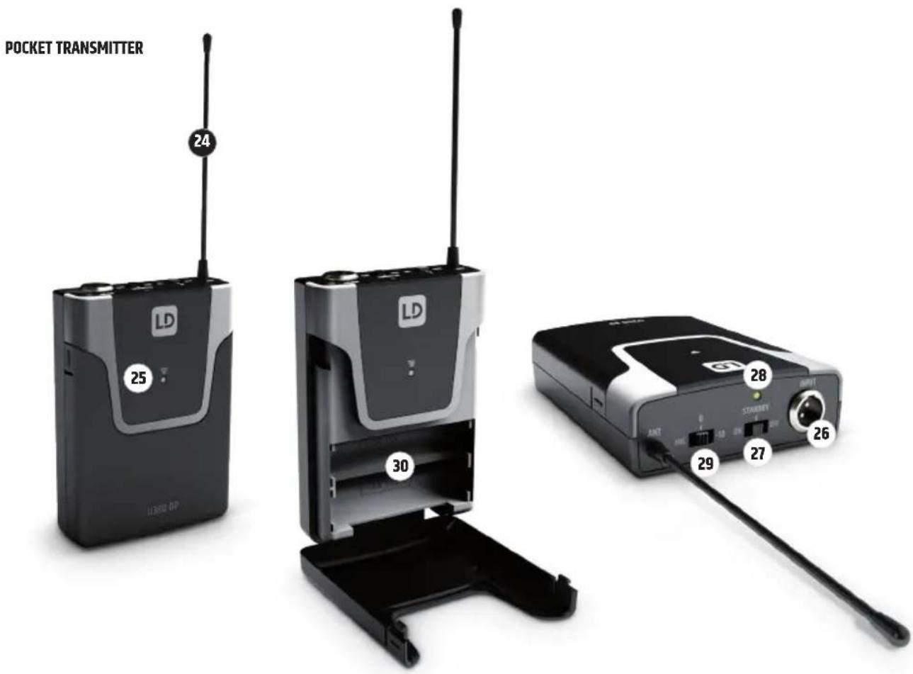
24 ANTENNA
Pocket transmitter antenna. For optimum reception, do not cover or kink.
25 IR INTERFACE
Infra-red interface for synchronising the radio channel from receiver and transmitter.
26 INPUT
3-pin mini XLR socket to connect a headset, Lavalier or instrument microphone and guitar cable.
27 ON / STANDBY / OFF
Switch to activate or deactivate the pocket transmitter (ON = transmitter is switched on, OFF = transmitter is switched off). In the STANDBY position, the transmitter is in operation but the audio signal is muted.
28 STATUS LED
If the charge status of the batteries is sufficient, the LED lights up green when the pocket transmitter is switched on. If the LED lights up red, the charge status is weak. In this case, replace the batteries (2 x AA/LR6 type, alkaline). During the synchronisation process, the LED flashes green and amber.
29 MIC / 0dB / -10dB
For setting the input sensitivity. Adjust the sensitivity so that an active signal (speech, vocals, guitar...) causes the amber-coloured level-LED on the receiver to light up. If the red PEAK LED lights up or flashes, reduce the sensitivity on the 3-position switch MIC/0dB/-10dB to the next lower value to prevent otherwise unwanted distortion. (Examples: Headset = MIC, guitar with passive pickups = 0dB, guitar with active pickups = -10dB).
30 BATTERY COMPARTMENT
To replace the batteries, open the battery compartment of the pocket transmitter by simultaneously pressing both markers on the sides of the battery cover and opening it forwards. Remove the used batteries and replace with new batteries (AA/LR6, alkaline), following the diagram in the battery compartment. Replace the battery compartment cover on the housing and click it into place. If the transmitter is not used for a long period, remove the batteries to avoid damage to the transmitter from leaking batteries.
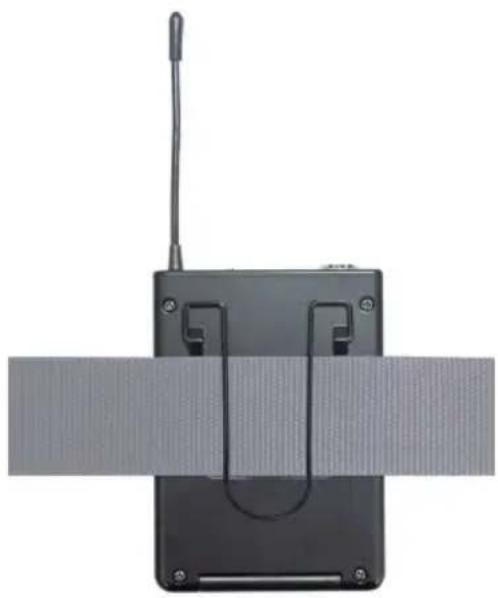
ATTACHING THE POCKET TRANSMITTER
Attach the transmitter to a belt or strap as shown.
natural_image
Black electronic device with antenna and U-shaped connector, resting on a textured surface (no text or symbols visible)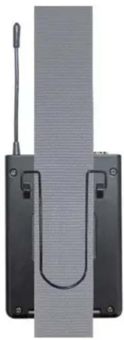
natural_image
Close-up of a black electronic device with a U-shaped component and a vertical strip, no visible text or symbols.PIN ALLOCATION FOR MINI XLR CONNECTOR (POCKET TRANSMITTER)
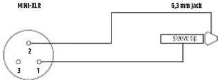
Guitar, bass and other high-impedance signal sources.
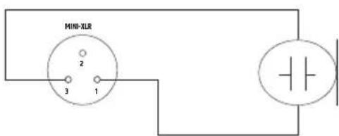
Condenser microphone with internal pull-up resistor.
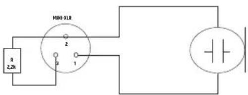
Condenser microphone without internal pull-up resistor.
TROUBLESHOOTING
| PROBLEM SYMPTOM SOLUTION | ||
| No audio signal or level too low | Receiver: No reception displayed on either antenna A or B. | Check if the transmitter is turned on.Check the batteries in the transmitter. |
| Receiver: Display lighting is switched off Check the power | supply for the receiver and whether the receiver is switched on. | |
| Receiver: No reception displayed on either antenna A or B.Transmitter: Device is switched on. Charge status of the batteries is ok. | Check whether radio frequency of the transmitter and the receiver are matching.Reduce the distance between transmitter and receiver.Ensure that there is a direct line of sight between the transmitter and the receiver.Ensure that the antennas on the receiver are positioned in an upward V-shape. | |
| Receiver: Reception on antenna A or B is displayed. Increase the signal level or increase the input sensitivity on the pocket transmitter. | ||
| Distortion and interference Receiver: Radio signal is displayed Remove possible sources of interference (digital devices, other radio systems). | ||
| Distorted sound Transmitter: Status LED is lit up red.Receiver: Peak LED on the receiver is lit. | Replace the batteries in the transmitter.Reduce the signal level or reduce the input sensitivity on the pocket transmitter. | |
OPTIONAL ACCESSORIES
LDU500CH - microphone head with condenser capsule and hypercardioid pickup pattern (for hand-held transmitters, matt black)
LDU500DH – microphone head with dynamic capsule and hypercardioid pickup pattern (for hand-held transmitters, matt black)
LDU500CC - microphone head with condenser capsule and cardioid pickup pattern (for hand-held transmitters, matt silver)
LDU500DC - microphone head with dynamic capsule and cardioid pickup pattern (for hand-held transmitters, matt silver)
LDWS100MH3 - beige-coloured headset with condenser microphone (for pocket transmitters)
LDWS100MH1 - black headset with condenser microphone (for pocket transmitters)
LDWS1000MW - clip microphone for wind instruments (for pocket transmitters)
LDWS100ML - Lavalier microphone (for pocket transmitters)
LDWS100GC - guitar cable (for pocket transmitters)
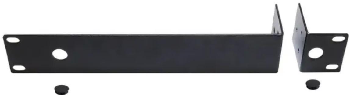
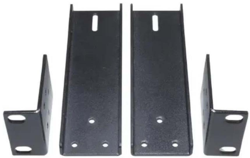
LDU300RK - 19" rack mounting kit for the installation of a single receiver (2 rack-mount brackets, 2 caps and 1 set of screws included).
natural_image
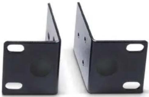
Two black metal structural beams with mounting holes, shown from different angles (no text or symbols visible)LDU300RK2 - 19" rack mounting kit for the installation of a dual receiver (includes blanking plugs and mounting screws).
natural_image
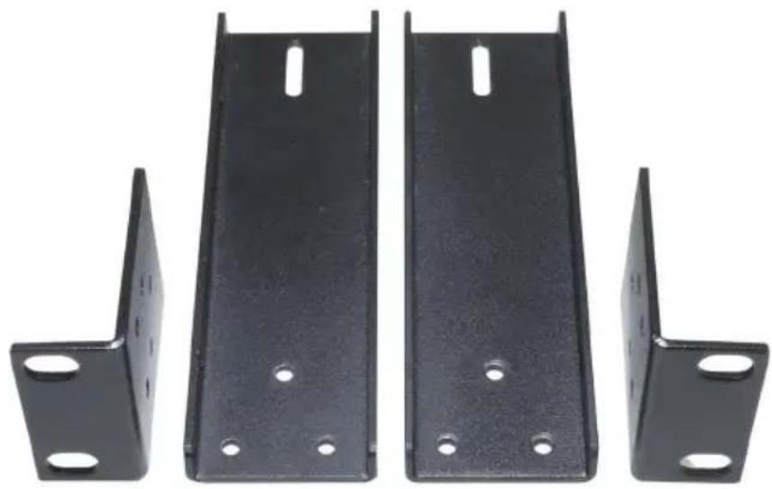
Two black metal bracket components with circular holes, shown side by side (no text or symbols visible)LDU500RK2 - 19" rack mounting kit for the installation of two single receivers (2 rack-mount brackets, 2 connectors and 1 set of screws included).
natural_image
Four black metal bracket components with mounting holes, shown from different angles (no text or symbols visible)Installation
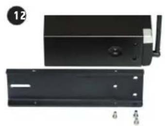
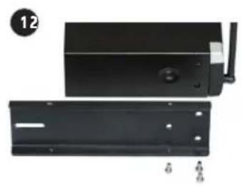
- Attach connectors (receiver A on the right-hand side, receiver B on the left-hand side).
- Screw both receivers together.
- Attach brackets (receiver A on the left-hand side, receiver B on the right-hand side).
natural_image
Two black metal panels with mounting holes and a small white panel on top, shown from different angles (no text or symbols visible)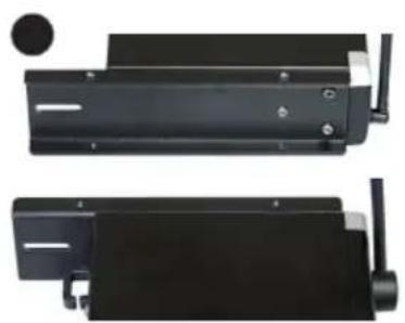
natural_image
Two views of a black mechanical device with mounting holes and a circular inset showing a hole (no text or symbols visible)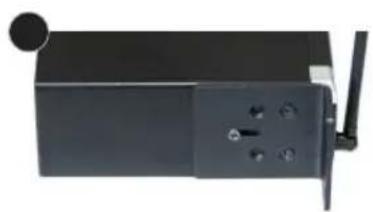
natural_image
Black rectangular electronic device with a small antenna and control buttons (no visible text or symbols)TECHNICAL DATA
RECEIVER
Itemnumber: LDU3047R LDU3051R LDU305R LDU306R LDU308R
Receiver type: UHF diversity UHF diversity UHF diversity UHF diversity UHF diversity
Modulation: FM FM FM FM FM
Frequency range: 470 - 490 MHz 514 - 542 MHz 584-608 MHz 655-679 MHz 823-832 MHz &
863-865 MHz
Channels: 12 12 12 12 12
| Antenna connectors: | 2 x fixed antennas | 2 x fixed antennas | 2 x fixed antennas | 2 x fixed antennas | 2 x fixed antennas |
| Frequency response: | 25-16000 Hz | 25-16000 Hz | 25-16000 Hz | 25-16000 Hz | 25-16000 Hz |
| Noise reduction: | Squelch, fixed level | Squelch, fixed level | Squelch, fixed level | Squelch, fixed level | Squelch, fixed level |
| THD (system): | <0.3% | <0.3% | <0.3% | <0.3% | <0.3% |
| Signal-to-noise ratio (system): | >104dB | >104dB | >104dB | >104dB | >104dB |
| Balanced output: | XLR | XLR | XLR | XLR | XLR |
| Unbalanced output: | 6.3 mm jack 6.3 mm jack 6.3 mm jack 6.3 mm jack | ||||
| Audio output level (balanced): | +10dBu | +10dBu +10dBu | +10dBu +10dBu | ||
| Audio output level (unbalanced): | +7dBV/+2.5dBV (switchable line/ instrument) | +7dBV/+2.5dBV (switchable line/ instrument) | +7dBV/+2.5dBV (switchable line/ instrument) | +7dBV/+2.5dBV (switchable line/ instrument) | +7dBV/+2.5dBV (switchable line/ instrument) |
| Controls: | POWER, + / - channel select, ASC, VOL vol-ume control, switch INSTRUMENT/LINE | POWER, + / - channel select, ASC, VOL vol-ume control, switch INSTRUMENT/LINE | POWER, + / - channel select, ASC, VOL vol-ume control, switch INSTRUMENT/LINE | POWER, + / - channel select, ASC, VOL vol-ume control, switch INSTRUMENT/LINE | POWER, + / - channel select, ASC, VOL vol-ume control, switch INSTRUMENT/LINE |
| Indicators: | 2 digit LC display, 5-segment LED level meter, antenna A/B LEDs | 2 digit LC display, 5-segment LED level meter, antenna A/B LEDs | 2 digit LC display, 5-segment LED level meter, antenna A/B LEDs | 2 digit LC display, 5-segment LED level meter, antenna A/B LEDs | 2 digit LC display, 5-segment LED level meter, antenna A/B LEDs |
| Operating voltage: | 12V DC, 500 mA | 12V DC, 500 mA | 12V DC, 500 mA | 12V DC, 500 mA | 12V DC, 500 mA |
| Ambient temperature (in operation): | 5°C to 40°C | 5°C to 40°C | 5°C to 40°C | 5°C to 40°C | 5°C to 40°C |
| Relative humidity: | 20% to 80% (non-condensing) | 20% to 80% (non-condensing) | 20% to 80% (non-condensing) | 20% to 80% (non-condensing) | 20% to 80% (non-condensing) |
| Dimensions (W x H x D): | 211 x 43 x 120 mm | 211 x 43 x 120 mm | 211 x 43 x 120 mm | 211 x 43 x 120 mm | 211 x 43 x 120 mm |
| Weight: | 0.7 kg | 0.7 kg | 0.7 kg | 0.7 kg | 0.7 kg |
| Accessories included: | power adapter | power adapter | power adapter | power adapter | power adapter |
| Features: | infra-red frequency synchronisation, pilot tone | infra-red frequency synchronisation, pilot tone | infra-red frequency synchronisation, pilot tone | infra-red frequency synchronisation, pilot tone | infra-red frequency synchronisation, pilot tone |
DUAL RECEIVER
Itemnumber: LDU3047R2 LDU3051R2 LDU305R2 LDU306R2 LDU308R2
Receiver type: UHF diversity UHF diversity UHF diversity UHF diversity
Modulation: FM FM FM FM FM
Frequency range: 470 - 490 MHz 514 - 542 MHz 584-608 MHz 655-679 MHz 823-832 MHz 6
863-865 MHz
Channels: 12 12 12 12 12
| Antenna connectors: | 2 x fixed antennas | 2 x fixed antennas | 2 x fixed antennas | 2 x fixed antennas | 2 x fixed antennas |
| Frequency response: | 25-16000 Hz | 25-16000 Hz | 25-16000 Hz | 25-16000 Hz | 25-16000 Hz |
| Noise reduction: | Squelch, fixed level | Squelch, fixed level | Squelch, fixed level | Squelch, fixed level | Squelch, fixed level |
| THD (system): | <0.3% | <0.3% | <0.3% | <0.3% | <0.3% |
| Signal-to-noise ratio (system): | >104dB | >104dB | >104dB | >104dB | >104dB |
| Balanced output: | 2x XLR | 2x XLR | 2x XLR | 2x XLR | 2x XLR |
| Unbalanced output: | 2x 6.3 mm jack | 2x 6.3 mm jack | 2x 6.3 mm jack | 2x 6.3 mm jack | 2x 6.3 mm jack |
| Balanced output MIX OUT: | XLR | XLR | XLR | XLR | XLR |
| Unbalanced output MIX OUT: | 6.3 mm jack 6.3 mm jack 6.3 mm jack 6.3 mm jack 6.3 mm jack | ||||
| Audio output level (balanced): | +10dBu | +10dBu +10dBu | +10dBu +10dBu | ||
| Audio output level (unbalanced): | +7dBV/+2.5dBV (switchable line/ instrument) | +7dBV/+2.5dBV (switchable line/ instrument) | +7dBV/+2.5dBV (switchable line/ instrument) | +7dBV/+2.5dBV (switchable line/ instrument) | +7dBV/+2.5dBV (switchable line/ instrument) |
| Controls: | POWER, 2x + / - channel select, 2x ASC, 2x VOL Volume control, 2x switch INSTRUMENT/LINE | POWER, 2x + / - channel select, 2x ASC, 2x VOL Volume control, 2x switch INSTRUMENT/LINE | POWER, 2x + / - channel select, 2x ASC, 2x VOL Volume control, 2x switch INSTRUMENT/LINE | POWER, 2x + / - channel select, 2x ASC, 2x VOL Volume control, 2x switch INSTRUMENT/LINE | |
| Indicators: | 2x 2 digit LC display, 2x 5-segment LED level meter, 2x antenna A / B LEDs | 2x 2 digit LC display, 2x 5-segment LED level meter, 2x antenna A / B LEDs | 2x 2 digit LC display, 2x 5-segment LED level meter, 2x antenna A / B LEDs | 2x 2 digit LC display, 2x 5-segment LED level meter, 2x antenna A / B LEDs | 2x 2 digit LC display, 2x 5-sesegment LED level meter, 2x antenna A / B LEDs |
| Operating voltage: | 12V DC, 500 mA | 12V DC, 500 mA | 12V DC, 500 mA | 12V DC, 500 mA | 12V DC, 500 mA |
| Ambient temperature (in operation): | 5°C to 40°C | 5°C to 40°C | 5°C to 40°C | 5°C to 40°C | 5°C to 40°C |
| Relative humidity: | 20% to 80% (non-condensing) | 20% to 80% (non-condensing) | 20% to 80% (non-condensing) | 20% to 80% (non-condensing) | 20% to 80% (non-condensing) |
| Dimensions (W x H x D): | 410 x 43 x 120mm | 410 x 43 x 120mm | 410 x 43 x 120mm | 410 x 43 x 120mm | 410 x 43 x 120mm |
| Weight: | 1.3 kg | 1.3 kg | 1.3 kg | 1.3 kg | 1.3 kg |
| Accessories included: | Power adapter, audio cable, rack kit | Power adapter, audio cable, rack kit | Power adapter, audio cable, rack kit | Power adapter, audio cable, rack kit | Power adapter, audio cable, rack kit |
| Features: | Infrared frequency synchronisation, pilot tone | Infrared frequency synchronisation, pilot tone | Infrared frequency synchronisation, pilot tone | Infrared frequency synchronisation, pilot tone | Infrared frequency synchronisation, pilot tone |
HAND-HELD TRANSMITTER
Item number: LDU3047MD LDU3051MD LDU305MD LDU306MD LDU308MD
Modulation: FM FM FM FM FM
Frequency range: 470 - 490 MHz 514 - 542 MHz 584-608 MHz 655-679 MHz 823-832 MHz &
863-865 MHz
Channels: 12 12 12 12 12
Microphone type: Dynamic Dynamic Dynamic Dynamic Dynamic
| Polar pattern: | Cardioid | Cardioid | Cardioid | Cardioid | Cardioid |
| Frequency response: | 55-16000 Hz 55-16000 Hz 55-16000 Hz 55-16000 Hz | ||||
| RF output power: | 10 mW PEP | 10 mW PEP | 10 mW PEP | 10 mW PEP | 10 mW PEP |
| Antenna gain: | 0.5 dBi | 0.5 dBi | 0.5 dBi | 0.5 dBi | 0.5 dBi |
| Controls: | Power on/off | Power on/off | Power on/off | Power on/off | Power on/off |
| Indicators: | Status LED | Status LED | Status LED | Status LED | Status LED |
| Power supply: | 2 x AA batteries | 2 x AA batteries | 2 x AA batteries | 2 x AA batteries | 2 x AA batteries |
| Operating time: up to 10 h | (depending on batteries) | up to 10 h (depending on batteries) | up to 10 h (depending on batteries) | up to 10 h (depending on batteries) | up to 10 h (depending on batteries) |
| Ambient temperature (in operation): | 5°C to 40°C | 5°C to 40°C | 5°C to 40°C | 5°C to 40°C | 5°C to 40°C |
| Relative humidity: | 20% to 80% (non-condensing) | 20% to 80% (non-condensing) | 20% to 80% (non-condensing) | 20% to 80% (non-condensing) | 20% to 80% (non-condensing) |
| Dimensions (L x ∅): | 257 x 50 mm | 257 x 50 mm | 257 x 50 mm | 257 x 50 mm | 257 x 50 mm |
| Weight (without batteries): | 0.235 kg | 0.235 kg | 0.235 kg | 0.235 kg | 0.235 kg |
| Accessories included: | 2 x AA batteries | 2 x AA batteries | 2 x AA batteries | 2 x AA batteries | 2 x AA batteries |
| Features: | infra-red frequency synchronisation, pilot tone, microphone head interchangeable | infra-red frequency synchronisation, pilot tone, microphone head interchangeable | infra-red frequency synchronisation, pilot tone, microphone head interchangeable | infra-red frequency synchronisation, pilot tone, microphone head interchangeable | infra-red frequency synchronisation, pilot tone, microphone head interchangeable |
BODY PACK TRANSMITTER
| Item number: | LDU3047BP | LDU3051BP | LDU305BP | LDU306BP | LDU308BP |
| Modulation: FM FM FM FM FM | |||||
Frequency range: 470 - 490 MHz 514 - 542 MHz 584-608 MHz 655-679 MHz 823-832 MHz &
863-865 MHz
| Channels: | 12 | 12 | 12 | 12 | 12 |
| Input: | 3-pin mini-XLR(low-Z + phantom power/high-Z) | 3-pin mini-XLR(low-Z + phantom power/high-Z) | 3-pin mini-XLR(low-Z + phantom power/high-Z) | 3-pin mini-XLR(low-Z + phantom power/high-Z) | 3-pin mini-XLR(low-Z + phantom power/high-Z) |
| Frequency response: 25-16,000 Hz 25-16,000 Hz 25-16,000 Hz | 25-16,000 Hz 25-16,000 Hz | ||||
| RF output power: | 10 mW PEP | 10 mW PEP | 10 mW PEP | 10 mW PEP | 10 mW PEP |
| Antenna gain: | 0.5 dBi | 0.5 dBi | 0.5 dBi | 0.5 dBi | 0.5 dBi |
| Controls: | ON/STANDBY/OFF,MIC/0/-10 | ON/STANDBY/OFF,MIC/0/-10 | ON/STANDBY/OFF,MIC/0/-10 | ON/STANDBY/OFF,MIC/0/-10 | ON/STANDBY/OFF,MIC/0/-10 |
| Indicators: | Status LED | Status LED | Status LED | Status LED | Status LED |
| Power supply: | 2 x AA batteries | 2 x AA batteries | 2 x AA batteries | 2 x AA batteries | 2 x AA batteries |
| Operating time: Up to 10 h | (upending on batteries) | Up to 10 h (depending on batteries) | Up to 10 h (depending on batteries) | Up to 10 h (depending on batteries) | Up to 10 h (depending on batteries) |
| Ambient temperature (in operation): | 5°C to 40°C | 5°C to 40°C | 5°C to 40°C | 5°C to 40°C | 5°C to 40°C |
| Relative humidity: | 20% to 80%(non-condensing) | 20% to 80%(non-condensing) | 20% to 80%(non-condensing) | 20% to 80%(non-condensing) | 20% to 80%(non-condensing) |
| Dimensions(W x H x D): | 65 x 91 x 25 mm | 65 x 91 x 25 mm | 65 x 91 x 25 mm | 65 x 91 x 25 mm | 65 x 91 x 25 mm |
| Weight(without batteries): | 0.085 kg 0.085 kg 0.085 kg 0.085 kg 0.085 kg | ||||
| Accessories included: | 2 x AA batteries | 2 x AA batteries | 2 x AA batteries | 2 x AA batteries | 2 x AA batteries |
| Features: | infra-red frequency synchronisation,pilot tone | infra-red frequency synchronisation,pilot tone | infra-red frequency synchronisation,pilot tone | infra-red frequency synchronisation,pilot tone | infra-red frequency synchronisation,pilot tone |
| Item number: LDWS100MH1 LDWS100ML LDWS1000MW | ||
| Microphone type: Headset Lavalier | microphone | Wind instrument microphone |
| Capsule: Back-electret condenser | Back-electret condenser | Back-electret condenser |
| Polar pattern: Cardioid Cardioid Cardioid | ||
| Frequency response: 20–20000 Hz 20–20000 Hz 20–18000 Hz | ||
| Connector: 3-pin mini-XLR 3-pin mini-XLR 3-pin mini-XLR | ||
Accessories included: Foam windscreen Foam windscreen Foam windscreen
GUITAR CABLE FOR BODY PACK TRANSMITTER
Item number: LDWS100GC
Connector 1: 3-pin mini-XLR
Connector 2: 6.3 mm jack
Cable length: 1.5 m
MANUFACTURER'S DECLARATIONS
MANUFACTURER'S WARRANTY & LIMITATIONS OF LIABILITY
You can find our current warranty conditions and limitations of liability at: https://cdn-shop.adamhall.com/media/pdf/MANUFACTURERS-DECLARA-TIONS_LD_SYSTEMS.pdf To request warranty service for a product, please contact Adam Hall GmbH, Adam-Hall-Str. 1, 61267 Neu Anspach / Email: Info@adamhall.com / +49 (0)6081 / 9419-0.

CORRECT DISPOSAL OF THIS PRODUCT
(valid in the European Union and other European countries with a differentiated waste collection system)
This symbol on the product, or on its documents indicates that the device may not be treated as household waste. This is to avoid environmental damage or personal injury due to uncontrolled waste disposal. Please dispose of this product separately from other waste and have it recycled to promote sustainable economic activity. Household users should contact either the retailer where they purchased this product, or their local government office, for details on where and how they can recycle this item in an environmentally friendly manner. Business users should contact their supplier and check the terms and conditions of the purchase contract. This product should not be mixed with other commercial waste for disposal.
FCC STATEMENT
This device complies with Part 15 of the FCC Rules. Operation is subject to the following two conditions:
(1) This device may not cause harmful interference, and
(2) This device must accept any interference received, including interference that may cause undesired operation
NOTE: This equipment has been tested and found to comply with the limits for a Class B digital device, pursuant to Part 15 of the FCC Rules. These limits are designed to provide reasonable protection against harmful interference in a residential installation. This equipment generates, uses and can radiate radio frequency energy and, if not installed and used in accordance with the instructions, may cause harmful interference to radio communications. However, there is no guarantee that interference will not occur in a particular installation. If this equipment does cause harmful interference to radio or television reception, which can be determined by turning the equipment off and on, the user is encouraged to try to correct the interference by one or more of the following measures:
- Reorient or relocate the receiving antenna.
- Increase the separation between the equipment and receiver.
- Connect the equipment into an outlet on a circuit different from that to which the receiver is connected.
- Consult the dealer or an experienced radio/TV technician for help.
CE Compliance
Adam Hall GmbH states that this product meets the following guidelines (where applicable):
R&TTE (1999/5/EC) or RED (2014/53/EU) from June 2017
Low voltage directive (2014/35/EU)
EMV directive (2014/30/EU)
RoHS (2011/65/EU)
The complete declaration of conformity can be found at www.adamhall.com.
Furthermore, you may also direct your enquiry to info@adamhall.com.
EU DECLARATION OF CONFORMITY
Hereby, Adam Hall GmbH declares that this radio equipment type is in compliance with Directive 2014/53/EU.
The full text of the EU declaration of conformity is available at the following
internet address: www.adamhall.com/compliance/
DEUTSCH
Kondensatormikrofon ohne internem Pull-up-Widerstand.
FEHLERSUCHE
natural_image
Two black metal structural beams with mounting holes, shown from different angles (no text or symbols visible)natural_image
Two black metal bracket plates with mounting holes, shown side by side (no text or symbols visible)natural_image
Four black metal structural brackets with mounting holes, shown from different angles (no text or symbols visible)Montage
natural_image
Two black metal electronic components with mounting holes and a small white panel, shown from different angles (no text or symbols visible)
natural_image
Two views of a black mechanical device with mounting holes and a circular button (no text or symbols visible)
natural_image
Black rectangular electronic device with a circular knob and a small antenna, no visible text or symbols.TECHNISCHE DATEN
EMPFÄNGER
Modulation: FM FM FM FM FM
APPAREILS RELIÉS AU SECTEUR
14 BALANCED OUTPUT (SORTIE SYMÉTRIQUE)
natural_image
Two black electronic devices with antenna and cable bands, shown from different angles (no text or symbols visible)AFFECTATION DU CONNECTEUR MINI-XLR (ÉMETTEUR DE POCHE)
natural_image
Exterior view of a black metal bracket with mounting holes and two side mounting feet (no text or symbols)natural_image
Two black metal bracket plates with mounting holes, shown from side to top (no text or symbols visible)natural_image
Four black metal bracket components with mounting holes, shown from different angles (no text or symbols visible)Montage
natural_image
Two black metal components with labeled terminals and a small inset showing a device (no text or symbols visible)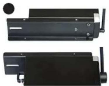
natural_image
Two views of a black mechanical device with a circular inset showing a hole (no text or symbols visible)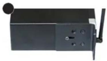
natural_image
Black rectangular electronic device with a small circular knob and a white antenna, no visible text or symbols.CARACTÉRISTIQUES TECHNIQUES
RÉCEPTEUR
(valid in the European Union and other European countries with waste separation)
DÉCLARATION DE CONFORMITÉ CE
natural_image
Two black electronic devices with antenna and U-shaped connectors, shown side by side against a textured gray background (no text or symbols visible)natural_image
Exterior view of a black metal bracket with mounting holes and two side mounting feet (no text or symbols)natural_image
Two black metal bracket plates with mounting holes, shown side by side (no text or symbols visible)natural_image
Four black metal bracket components with mounting holes, arranged in a V-shape (no text or symbols visible)Montaje
natural_image
Two black metal components with mounting holes and a label '12' in the top-left corner (no text or symbols on the main parts)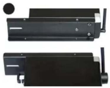
natural_image
Two black electronic device modules with visible ports and connectors, no text or symbols present.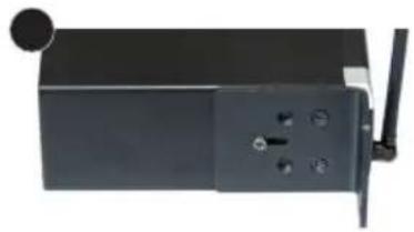
natural_image
Close-up of a black rectangular electronic device with a small circular knob and four mounting holes (no visible text or symbols)DATOS TÉCNICOS
RECEPTOR
natural_image
Two black metal bracket components with mounting holes, shown from different angles (no text or symbols visible)natural_image
Two black metal bracket plates with mounting holes, shown from side and top angles (no text or symbols visible)LDU500RK2 - ZESTAW DO ZAMOCOWANIA DWÓCH ODBIORNIKÓW W SZAFIE RACK 19" (W TYM 2 UCHWYTY MOCUJĄCE, 2 ELEMENTY ŁĄCZĄCE I 1 ZESTAW ŚRUB).
natural_image
Four black metal bracket components with mounting holes, shown from different angles (no text or symbols visible)MONTAZ
- PRZYKREĆ ŚRUBAMI ELEMENTY ŁĄCZĄCE (W ODBIORNIKU A PO PRAWEJ STRONIE, W ODBIORNIKU B PO LEWEJ STRONIE)
- POŁĄCZ OBA ODBIORNIKI ŚRUBAMI.
- PRZYKREĆ ŚRUBAMI UCHWYTY MOCUJĄCE (W ODBIORNIKU A PO LEWEJ STRONIE, W ODBIORNIKU B PO PRAWEJ STRONIE).
natural_image
Two black metal components with mounting holes and a label '12' in the top-left corner (no text or symbols on the main parts)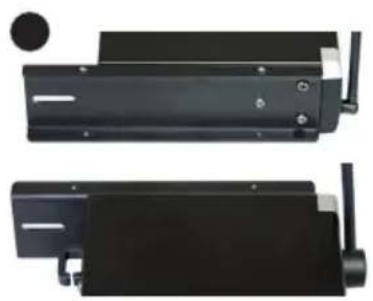
natural_image
Two black mechanical components with mounting holes and a circular inset showing a detail (no text or symbols visible)
natural_image
Black rectangular device with a circular knob and a white antenna, no visible text or symbols.DANE TECHNICZNE
ODBIORNIK
DEKLARACJA ZGODNOŚCI WE
natural_image
Two black electronic devices with attached wires, one showing a U-shaped cable and the other a flat panel (no text or symbols visible)natural_image
Two black metal structural beams with mounting holes, shown from different angles (no text or symbols visible)natural_image
Two black metal bracket plates with circular cutouts, shown against a white background (no text or symbols visible)natural_image
Four black metal bracket components with mounting holes, shown from different angles (no text or symbols visible)Montaggio
natural_image
Two black metal components with mounting holes and a label '12' in the top-left corner (no text or symbols on the main parts)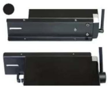
natural_image
Two views of a black mechanical device with a circular inset showing a hole (no text or symbols visible)
natural_image
Black rectangular electronic device with a circular knob and a white antenna, no visible text or symbols.DATI TECNICI
RICEVITORE
- U300® SERIES
- CONTENTS / INHALTSVERZEICHNIS / CONTENU / CONTENIDO / TREŚĆ / CONTENUTO
- ENGLISH
- DEUTSCH
- PREVENTIVE MEASURES
- FOR EQUIPMENT THAT CONNECTS TO THE POWER MAINS
- CAUTION:
- CAUTION! HIGH VOLUMES IN AUDIO PRODUCTS!
- INTRODUCTION
- Pilot tone
- Included
- CONNECTIONS, OPERATING AND DISPLAY ELEMENTS
- POWER
- CHANNEL DISPLAY
- CHANNEL + / -
- VOL
- IR INTERFACE
- ASC
- LEVEL INDICATOR
- ANTENNA A - B
- RECEPTION ANTENNAS A - B
- DC SOCKET
- CABLE STRAIN-RELIEF
- UNBALANCED OUTPUT
- ⑬ INSTRUMENT/LINE (UNBALANCED OUTPUT)
- BALANCED OUTPUT
- INSTRUMENT/LINE MIX OUT (UNBALANCED OUTPUT)
- MICROPHONE HEAD
- ON / OFF
- STATUS LED
- IR INTERFACE
- BATTERY COMPARTMENT COVER
- BATTERY COMPARTMENT
- ANTENNA
- IR INTERFACE
- INPUT
- ON / STANDBY / OFF
- STATUS LED
- MIC / 0dB / -10dB
- BATTERY COMPARTMENT
- ATTACHING THE POCKET TRANSMITTER
- PIN ALLOCATION FOR MINI XLR CONNECTOR (POCKET TRANSMITTER)
- OPTIONAL ACCESSORIES
- Installation
- TECHNICAL DATA
- DUAL RECEIVER
- Itemnumber: LDU3047R2 LDU3051R2 LDU305R2 LDU306R2 LDU308R2
- HAND-HELD TRANSMITTER
- Item number: LDU3047MD LDU3051MD LDU305MD LDU306MD LDU308MD
- BODY PACK TRANSMITTER
- GUITAR CABLE FOR BODY PACK TRANSMITTER
- MANUFACTURER'S DECLARATIONS
- MANUFACTURER'S WARRANTY & LIMITATIONS OF LIABILITY
- CORRECT DISPOSAL OF THIS PRODUCT
- FCC STATEMENT
- CE Compliance
- EU DECLARATION OF CONFORMITY
- Montage
- TECHNISCHE DATEN
- EMPFÄNGER
- APPAREILS RELIÉS AU SECTEUR
- BALANCED OUTPUT (SORTIE SYMÉTRIQUE)
- AFFECTATION DU CONNECTEUR MINI-XLR (ÉMETTEUR DE POCHE)
- CARACTÉRISTIQUES TECHNIQUES
- DÉCLARATION DE CONFORMITÉ CE
- Montaje
- DATOS TÉCNICOS
- RECEPTOR
- MONTAZ
- DANE TECHNICZNE
- DEKLARACJA ZGODNOŚCI WE
- Montaggio
- DATI TECNICI
Brand : LD Systems
Model : U308 MD
Category : Microphone