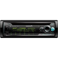
DMHW2700NEX - Car stereo PIONEER - Free user manual and instructions
Find the device manual for free DMHW2700NEX PIONEER in PDF.
Download the instructions for your Car stereo in PDF format for free! Find your manual DMHW2700NEX - PIONEER and take your electronic device back in hand. On this page are published all the documents necessary for the use of your device. DMHW2700NEX by PIONEER.
USER MANUAL DMHW2700NEX PIONEER
RÉCEPTEUR AV AVEC RDS
Installation Manual Manuel d’installation Manual de instalación2En WARNING Rear visibility systems (backup cameras) are required in certain new vehicles sold in the U.S. and Canada. U.S. regulations began according to a two year phase-in on May 1, 2016, and both the U.S. and Canada require that all such vehicles manufactured on or after May 1, 2018 have rear visibility systems. Owners of vehicles equipped with compliant rear visibility systems should not install or use this product in a way that alters or disables that system's compliance with applicable regulations. If you are unsure whether your vehicle has a rear visibility system subject to the U.S. or Canadian regulations, please contact the vehicle manufacturer or dealer.If your vehicle has a compliant backup camera that displays the backup view through the factory receiver, do not use the Pioneer receiver unless it is connected to and displays the same view as the factory backup camera. Connection to the factory backup camera will require an adaptor, sold separately. Not all vehicles may be able to connect. Please check with a qualified professional installer for installation options specific to your vehicle. Important safety information
- This product (×1)• Power cord (×1)• Pre out cord (×1)• SWC/Back Camera cord (×1)• AUX IN cord (×1)• USB cable (×1)• SiriusXM® cable (×1)• Flush surface screw (×6)• Truss head screw (×6)• Remote Control (×1) (DMH-W2770NEX) NOTE SiriusXM and all related marks and logos are trademarks of Sirius XM Radio, Inc. All rights reserved.• GPS antenna (×1)• Double-sided tape (×1)• Clamps (×3)• Microphone (×1)• Double-sided tape (×1)• Manual(s) (×1)• Warranty Card (×1)• Do not operate this product, any applications, or the rear view camera option (if purchased) if doing so will divert your attention in any way from the safe operation of your vehicle. Always observe safe driving rules and follow all existing traffic regulations. If you experience difficulty in operating this product, pull over, park your vehicle in a safe location and apply the parking brake Checking supplied items This product/ connection cables/ installation parts/ Remote Control GPS antenna/ installation parts Microphone/ installation parts Other items Connection Precautions Your new product and this manual3En English before making the necessary adjustments.
- Do not install this product where it may (i) obstruct the driver’s vision, (ii) impair the performance of any of the vehicle’s operating systems of safety features, including airbags, hazard lamp buttons, or (iii) impair the driver’s ability to safely operate the vehicle. In some cases, it may not be possible to install this product because of the vehicle type or the shape of the vehicle interior. WARNING Pioneer does not recommend that you install this product yourself. This product is designed for professional installation only. We recommend that only authorized Pioneer service personnel, who have special training and experience in mobile electronics, set up and install this product. NEVER SERVICE THIS PRODUCT YOURSELF. Installing or servicing this product and its connecting cables may expose you to the risk of electric shock or other hazards, and can cause damage to this product that is not covered by warranty. WARNING Do not take any steps to tamper with or disable the parking brake interlock system which is in place for your protection. Tampering with or disabling the parking brake interlock system could result in serious injury or death. CAUTION
- Secure all wiring with cable clamps or electrical tape. Do not allow any bare wiring to remain exposed.
- Do not directly connect the yellow lead of this product to the vehicle battery. If the lead is directly connected to the battery, engine vibration may eventually cause the insulation to fail at the point where the wire passes from the passenger compartment into the engine compartment. If the yellow lead’s insulation tears as a result of contact with metal parts, short-circuiting can occur, resulting in considerable danger.
- It is extremely dangerous to allow cables to become wound around the steering column or shift lever. Be sure to install this product, its cables, and wiring away in such so that they will not obstruct or hinder driving.
- Make sure that the cables and wires will not interfere with or become caught in any of the vehicle’s moving parts, especially the steering wheel, shift lever, parking brake, sliding seat tracks, doors, or any of the vehicle’s controls.
- Do not route wires where they will be exposed to high temperatures. If the insulation heats up, wires may become damaged, resulting in a short circuit or malfunction and permanent damage to the product.
- Do not shorten any leads. If you do, the protection circuit (fuse holder, fuse resistor or filter, etc.) may fail to work properly.
- Never feed power to other electronic products by cutting the insulation of the power supply lead of this product and tapping into the lead. The current capacity of the lead will be exceeded, causing overheating. Important safeguards Precautions before connecting the system
- Use this unit with a 12-volt battery and negative grounding only. Failure to do so may result in a fire or malfunction.
- To avoid shorts in the electrical system, be sure to disconnect the (–) battery cable before installation. WARNING
- When speaker output is used by 4 channels , use speakers over 50 W (Maximum input power) and between 4 Ω to 8 Ω (impedance value). Do not use 1 Ω to 3 Ω speakers for this unit.
- The black cable is ground. When installing this unit or power amp (sold separately), make sure to connect the ground wire first. Ensure that the ground wire is properly connected to metal parts of the car’s body. The ground wire of the power amp and the one of this unit or any other device must be connected to the car separately with different screws. If the screw for the ground wire loosens or falls out, it could result in fire generation of smoke or malfunction.
- When replacing the fuse, be sure to only use a fuse of the rating prescribed on this product.
- This product cannot be installed in a vehicle without ACC (accessory) position on the ignition switch.
- To avoid short-circuiting, cover the disconnected lead with insulating tape. It is especially important to insulate all unused speaker leads, which if left uncovered may cause a short circuit.
- For connecting a power amp or other devices to this product, refer to the manual for the product to be connected.
- The graphical symbol placed on the product means direct current.
- When the ignition switch is turned on (ACC ON), a control signal is output through the blue/white lead. Connect to Before installing this product To prevent damage Notice for the blue/ white lead Ground wire POWER AMP Other devices (Another electronic device in the car) Metal parts of car’s body *1 Non supplied for this unit ACC position No ACC position4En an external power amp’s system remote control terminal, the auto-antenna relay control terminal, or the antenna booster power control terminal (max. 300 mA 12 V DC). The control signal is output through the blue/white lead, even if the audio source is switched off. GPS antenna 3.55 m (11 ft. 8 in.) Microphone 3 m (9 ft. 10-1/8 in.) This product Antenna jack Connector 1 (REAR VIEW CAMERA IN/ MUTE/STEERING WHEEL CONTROL) Connector 2 (AUX IN) Pre out supply SiriusXM Connect Vehicle Tuner Be sure to use the SiriusXM cable supplied with this product. Refer to the installation guide for SiriusXM Connect Vehicle Tuner (sold separately). Fuse (10 A) Power supply To connector 1 SWC/Back Camera cord Wired remote input (STEERING WHEEL CONTROL) Hard-wired remote control adapter can be connected (sold separately). Brown (REAR VIEW CAMERA IN) Yellow/black (MUTE) To power supply Power cord Yellow To terminal supplied with power regardless of ignition switch position. Red To electric terminal controlled by ignition switch (12 V DC) ON/OFF Orange/white To lighting switch terminal. Black (ground) To vehicle (metal) body. Violet/white Of the two lead wires connected to the back lamp, connect the one in which the voltage changes when the gear shift is in the REVERSE (R) position. This connection enables the unit to sense whether the car is moving forward or backward. Pink Car speed signal input Blue/white This product Power cord Connect to system control terminal of the power amp (max. 300 mA 12 V DC). Light green Used to detect the ON/OFF status of the parking brake. This lead must be connected to the power supply side of the parking brake switch. Power supply side Parking brake switch Ground side NOTE The position of the speed detection circuit and the position of the parking brake switch vary depending on the vehicle model. For details, consult your authorized Pioneer dealer or an installation professional. To power supply Power cord Left Right Front speaker Rear speaker White White/black Gray Gray/black Green Green/black Violet Violet/black NOTE With a two-speaker system, do not connect anything to the speaker leads that are not connected to speakers. Speaker leads5En English Important The speaker leads are not used when this connection is in use. Subwoofer output (SUBWOOFER OUT L/SUBWOOFER OUT R) RCA cable (sold separately) Power amp Front output (FRONT OUT L/FRONT OUT R) Rear output (REAR OUT L/REAR OUT R) Yellow/black (MUTE) If you use an equipment with Mute function, wire this lead to the Audio Mute lead on that equipment. If not, keep the Audio Mute lead free of any connections. Pre out cord To pre out supply To connector 1 System remote control Connect to Blue/white cable. Rear speaker Front speaker Subwoofer Power amp (sold separately) NOTES
- For details on how to connect an external device using a separately sold cable, refer to the manual for the cable.
- For details concerning the connection and operations of iPhone or smartphone, refer to the Operation Manual.
- iPhone and Lightning are trademarks of Apple Inc., registered in the U.S. and other countries. iPhone with Lightning connector USB interface cable for iPhone (sold separately) USB cable 1.5 m (4 ft. 11 in.) USB port Smartphone USB - micro USB cable (USB Type-A to micro USB Type-B) (sold separately) USB Type-C® cable (USB Type-A to USB Type-C) (sold separately) USB cable 1.5 m (4 ft. 11 in.) USB port NOTES
- Due to the USB standard, the total length when a USB Type-A to micro USB Type-B cable ( ) and a USB cable ( ) are connected cannot exceed 2 m (6 ft. 6 in.), and when a USB Type-A to USB Type-C cable ( ) and a USB cable ( ) are connected cannot exceed 4 m (13 ft. 1 in.). If you use a cable other than the above conditions, the main unit function may not operate properly.
- Android is a trademark of Google LLC.
- USB Type-C® and USB-C® are registered trademarks of USB Implementers Forum. About rear view camera When you use the rear view camera, the rear view image is automatically switched iPhone and smartphone iPhone with Lightning connector Connecting via the USB port Smartphone (Android™ device) Connecting via the USB port Camera6En from the video by moving the shift lever to REVERSE (R). Camera View mode also allows you to check what is behind you while driving. WARNING USE INPUT ONLY FOR REVERSE OR MIRROR
- The screen image may appear reversed.
- With the rear view camera you can keep an eye on trailers, or back into a tight parking spot. Do not use for entertainment purposes.
- Objects in rear view may appear closer or more distant than in reality.
- The image area of full-screen images displayed while backing or checking the rear of the vehicle may differ slightly. This product Connector 1 Power supply To connector 1 To power supply SWC/Back Camera cord Power cord Brown (REAR VIEW CAMERA IN) Violet/white (REVERSE-GEAR SIGNAL INPUT) Refer to Power cord on page 4. RCA cable (sold separately) To video output Rear view camera (sold separately) NOTES
- Connect only the rear view camera to REAR VIEW CAMERA IN. Do not connect any other equipment.
- Some appropriate settings are required to use rear view cameras. For details, refer to the Operation Manual. This product Pre out supply Connector 2 To connector 2 To pre out supply Pre out cord Mini-jack AV cable (sold separately) AUX input (AUX IN) AUX IN cord Yellow (REAR MONITOR OUT) Yellow Red, white RCA cables (sold separately) To video input Rear display with RCA input jacks To video output To audio outputs External video component (sold separately) WARNING NEVER install the rear display in a location that enables the driver to watch the video source while driving. This product’s rear video output is for connection of a display to enable passengers in the rear seats to watch the video source. CAUTION Be sure to use a mini-jack AV cable (sold separately) for wiring. If you use other cables, the wiring position might differ resulting in disturbed images and sounds. External video component and the display L : Left audio (White) R : Right audio (Red) V : Video (Yellow) G : Ground7En English CAUTION
- Never install this product in places where, or in a manner that:– Could injure the driver or passengers if the vehicle stops suddenly.– May interfere with the driver’s operation of the vehicle, such as on the floor in front of the driver’s seat, or close to the steering wheel or shift lever.• To ensure proper installation, be sure to use the supplied parts in the manner specified. If any parts are not supplied with this product, use compatible parts in the manner specified after you have the part compatibility checked by your dealer. If parts other than supplied or compatible ones are used, they may damage internal parts of this product or they may work loose and the product may become detached.• Do not install this product where it may(i) obstruct the driver’s vision,(ii) impair the performance of any of the vehicle’s operating systems or safety features, including airbags, hazard lamp buttons or(iii) impair the driver’s ability to safely operate the vehicle.• Never install this product in front of or next to the place in the dashboard, door, or pillar from which one of your vehicle’s airbags would deploy. Please refer to your vehicle’s owner’s manual for reference to the deployment area of the frontal airbags.• Consult with your nearest dealer if installation requires drilling holes or other modifications of the vehicle.• Before making a final installation of this product, temporarily connect the wiring to confirm that the connections are correct and the system works properly.• Do not install this product in places subject to high temperatures or humidity, such as:– Places close to a heater, vent or air conditioner.– Places exposed to direct sunlight, such as on top of the dashboard.– Places that may be exposed to rain, such as close to the door or on the vehicle’s floor.• Install this product horizontally on a surface within 0 to 60 degrees tolerance.• When installing, to ensure proper heat dispersal when using this unit, make sure you leave ample space behind the rear panel and wrap any loose cables so they are not blocking the vents. Installation Precautions before installation Before installing Installation notes 1 Fastening this product to the factory radio-mounting bracket.Position this product so that its screw holes are aligned with the screw holes of the bracket, and tighten the screws at three locations on each side.Use either the truss head screws (5 mm × 9 mm) or flush surface screws (5 mm × 9 mm), depending on the shape of the bracket’s screw holes. TIP The amount of this unit's protrusion from the dashboard/console can be adjusted by shifting the position of the screw hole of this unit to the factory radio-mounting bracket. Factory radio-mounting bracket If the pawl interferes with installation, you may bend it down out of the way. Dashboard or console Truss head screw or flush surface screwBe sure to use the screws supplied with this product. CAUTION Do not cut the GPS antenna lead to shorten it or use an extension to make it longer. Altering the antenna cable could result in a short circuit or malfunction and permanent damage to this product.• The antenna should be installed on a level surface where radio waves will be blocked as little as possible. Radio waves cannot be received by the antenna if reception from the satellite is blocked. Installation using the screw holes on the side of this product Leave ample space 5 cm 5 cm Installing the GPS antenna Installation notes8En Dashboard Rear shelf
- Take care not to pull the antenna lead when removing the GPS antenna. The lead may become detached.
- Do not paint the GPS antenna, as this may affect its performance. WARNING Do not install the GPS antenna over any sensors or vents on the dashboard of the vehicle, as doing so may interfere with the proper functioning of such sensors or vents and may compromise the ability of the GPS antenna to properly and securely affix to the dashboard. GPS antenna Double-sided tape Clamps Use clamps to secure the lead where necessary inside the vehicle. NOTES
- Affix the GPS antenna on the surface as level as possible where the GPS antenna faces the window.
- Some models use window glass that does not allow signals from GPS satellites to pass through. On such models, install the GPS antenna on the outside of the vehicle. When installing the antenna inside the vehicle (on the dashboard or rear shelf) Make sure the surface is free of moisture, dust, grime, oil, etc., before affixing the GPS antenna.9En English
- Install the microphone in a place where its direction and distance from the driver make it easiest to pick up the driver’s voice.
- Be sure to turn off (ACC OFF) the product before connecting the microphone.